
LAG BOLTS
Super Industries
“Global Manufacturer of Heavy & Custom Engineered Fasteners for Oil & Gas, Power & EPC Contractors.”
1. Industry Context & System Relevance of Lag Bolts
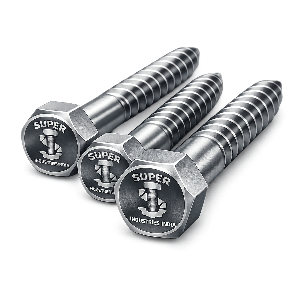
Lag Bolts are critical structural fasteners used in applications where high-load anchoring into wood, timber composites, or embedded anchoring systems is required without the use of a nut on the opposite side. Their design enables direct load transfer into the base material, making them essential in environments where through-bolting is either impractical or structurally inefficient.
Primary Functional Roles
Lag Bolts are deployed across multiple engineering sectors where structural integrity, load-bearing capacity, and installation accessibility are primary constraints.
Structural Wood-to-Metal Fastening
Used for connecting:
- Steel brackets to timber beams
- Base plates to wooden structural elements
- Reinforcement members in hybrid structures
Lag Bolts provide:
- High withdrawal resistance
- Controlled embedment behavior
- Reliable shear transfer across interfaces
Heavy Timber Construction
In engineered wood systems such as:
- Glulam beams
- Cross-laminated timber (CLT)
- Laminated veneer lumber (LVL)
Lag Bolts act as:
- Primary load connectors
- Reinforcement anchors at joints
- Structural stabilizers in compression zones
Infrastructure Anchoring
Used in:
- Guardrails
- Sound barriers
- Roadside timber supports
They enable:
- Fast installation without backside access
- Resistance to impact and vibration
- Field adaptability during installation
Utility Pole & Transmission Structures
Lag Bolts are extensively used in:
- Electrical distribution poles
- Cross-arm mounting
- Transformer bracket fixing
Engineering requirement:
- High resistance to cyclic loading
- Long-term outdoor durability
- Resistance to loosening under vibration
Railway & Bridge Timber Systems
Applications include:
- Timber sleepers
- Bridge decking systems
- Rail fastening supports
Lag Bolts provide:
- Secure anchoring under dynamic loads
- Resistance to fatigue due to repeated loading cycles
- Compatibility with treated timber
Industrial Equipment Base Fixing
Used where:
- Machinery is mounted on timber platforms
- Temporary industrial foundations are used
They allow:
- Strong anchorage without embedded nuts
- Rapid installation and removal
- Adaptability to site conditions
Why Lag Bolts Over Standard Bolts or Screws
Lag Bolts are selected over alternative fasteners due to the following engineering advantages:
| Parameter | Lag Bolts | Machine Bolts | Wood Screws |
|---|---|---|---|
| Installation | Single-side (no nut) | Requires access both sides | Single-side |
| Load Capacity | High | Very high (through-bolt) | Moderate |
| Withdrawal Resistance | High | Low | Moderate |
| Diameter Range | Large | Large | Small |
| Structural Use | Yes | Yes | Limited |
Key Engineering Advantages
- High shear capacity due to large shank diameter
- Superior withdrawal resistance via deep thread engagement
- No requirement for backside access
- Suitability for field installations in constrained environments
- Reduced installation complexity compared to through-bolting systems
Application Constraint – Non-Through Bolting
Lag Bolts are specifically designed for:
- Blind installations
- Timber structures where backside access is not feasible
- Retrofit and repair scenarios
This makes them essential in:
- Maintenance operations
- Infrastructure upgrades
- Remote installations
2. Technical Definition of Lag Bolts
Lag Bolts are large-diameter, externally threaded fasteners with a hexagonal or square head, designed to be installed into pre-drilled pilot holes in wood or equivalent materials, without the use of a mating nut.
Core Characteristics
- Coarse, deep thread profile
- Partial threading (thread + shank combination)
- High diameter-to-length ratio
- Head designed for high torque application
- Installed using wrench or impact tools
Structural Components
A typical Lag Bolt consists of:
- Head
- Hex or square
- Designed for torque transmission
- Provides bearing surface
- Shank
- Unthreaded portion
- Transfers shear loads
- Maintains alignment
- Threaded Section
- Coarse threads
- Engages with base material
- Responsible for withdrawal resistance
Installation Mechanism
- A pilot hole is drilled into the substrate
- The Lag Bolt is driven into the hole
- Threads cut or compress into the material
- Load is transferred through:
- Thread engagement
- Friction
- Bearing
Difference: Lag Bolts vs Machine Bolts
| Parameter | Lag Bolts | Machine Bolts |
|---|---|---|
| Nut Requirement | Not required | Required |
| Installation | Single-side | Through-hole |
| Thread Type | Coarse | Fine/standard |
| Application | Wood / anchors | Steel-to-steel |
| Load Transfer | Thread engagement | Clamping force |
Lag Bolts vs Structural Wood Screws
| Parameter | Lag Bolts | Structural Wood Screws |
|---|---|---|
| Diameter | Large | Medium |
| Installation Torque | High | Moderate |
| Load Capacity | Higher | Moderate |
| Pre-drilling | Required | Often optional |
| Application | Heavy structural | Light to medium structural |
Thread Geometry & Penetration
Thread design directly affects performance:
- Coarse pitch → Better grip in wood
- Deep threads → Increased withdrawal resistance
- Thread angle → Determines load transfer efficiency
- Penetration depth → Critical for structural capacity
Embedment Requirement
Effective embedment depth depends on:
- Material density
- Load requirements
- Bolt diameter
General engineering principle:
Minimum embedment depth ≥ 6 × diameter (application dependent)
Super Industries
Global Manufacturer of Heavy & Custom Engineered Fasteners & Flanges
3. Engineering & Load Transfer Principles
The performance of Lag Bolts is governed by mechanical interaction between the fastener and the base material, primarily wood or engineered substrates.
Thread Engagement Mechanics
When installed:
- Threads penetrate or compress wood fibers
- Fibers generate radial pressure against threads
- This creates:
- Frictional resistance
- Mechanical interlock
Result:
- High resistance to axial pull-out forces
Load Transfer Mechanisms
Lag Bolts transfer loads through three primary mechanisms:
1. Mechanical Interlock
- Threads physically engage material
- Primary contributor to withdrawal resistance
2. Frictional Resistance
- Generated by radial compression
- Enhances load stability
3. Bearing Resistance
- Head transfers load to surface
- Prevents over-penetration
Shear vs Withdrawal Behavior
Shear Load
- Acts perpendicular to bolt axis
- Resisted by:
- Shank diameter
- Material shear strength
Withdrawal Load
- Acts along bolt axis
- Resisted by:
- Thread engagement
- Embedment depth
- Material density
Head Bearing Pressure Distribution
The head of the Lag Bolt:
- Distributes load across contact surface
- Prevents localized crushing
- Maintains joint integrity
Design consideration:
- Washer usage may be required for soft materials
Pull-Out Resistance Theory
Pull-out resistance depends on:
- Thread diameter
- Embedment depth
- Wood density
- Thread geometry
Higher density materials provide:
- Greater resistance
- Improved long-term stability
Shear Plane Behavior
In shear loading:
- Failure occurs across the bolt cross-section
- Shear planes may be:
- Single shear
- Double shear
Design must consider:
- Cross-sectional area
- Material strength
- Load distribution
Embedment Depth Engineering
Embedment depth directly affects:
- Withdrawal capacity
- Load distribution
- Failure resistance
Key considerations:
- Insufficient depth → Pull-out failure
- Excessive depth → Installation inefficiency
Failure Modes in Lag Bolts
Typical failure mechanisms include:
- Thread Stripping
- Occurs in low-density materials
- Wood Splitting
- Due to improper pilot hole size
- Excessive torque
- Bolt Shear Failure
- Under high transverse loads
- Head Failure
- Due to over-tightening
- Withdrawal Failure
- Insufficient embedment
Friction vs Mechanical Locking
| Mechanism | Contribution |
|---|---|
| Friction | Secondary |
| Mechanical Interlock | Primary |
| Bearing | Supportive |
Design Considerations
Engineers must evaluate:
- Load direction (shear vs axial)
- Material properties
- Environmental conditions
- Installation constraints
- Safety factors
4. Applicable Standards (ASTM / DIN / ISO / ASME)
Lag Bolts used in structural and infrastructure applications are governed by multiple international standards that define mechanical properties, dimensional tolerances, material composition, and inspection requirements. Selection of the applicable standard depends on load conditions, environmental exposure, and project specifications.
ASTM Standards
ASTM A307 — Carbon Steel Bolts (General Structural Use)
Scope:
- Covers low to medium strength carbon steel bolts
- Commonly used for general construction and non-critical structural applications
Relevance to Lag Bolts:
- Suitable for timber structures with moderate load requirements
- Applicable where high tensile strength is not mandatory
Mechanical Characteristics:
- Tensile strength: ~414 MPa (minimum)
- Limited hardness control
- Not intended for high dynamic loads
ASTM A325 — High-Strength Structural Bolting (Contextual Use)
Scope:
- High-strength bolts for steel-to-steel structural connections
Relevance in Lag Bolt Context:
- Not a direct lag bolt standard, but material equivalence may be applied
- Used where higher load capacity and structural performance are required
Application Consideration:
- Requires controlled heat treatment
- Used in hybrid systems (steel + timber interface)
ASTM A449 — High Strength Bolts, Quenched and Tempered
Scope:
- Covers high-strength bolts exceeding A325 in certain configurations
Relevance:
- Suitable for heavy-duty lag bolts with high load demand
- Applicable in infrastructure and industrial applications
ASTM A36 — Structural Steel
Scope:
- General structural steel material
Use in Lag Bolts:
- Used in custom-manufactured lag bolts
- Suitable for fabricated fasteners with moderate strength requirements
DIN Standard
DIN 571 — Hexagon Head Wood Screws (Lag Screws)
Primary Reference Standard for Lag Bolts
Defines:
- Thread geometry
- Dimensions
- Head configuration
- Length ranges
Engineering Relevance:
- Widely accepted for European and global EPC projects
- Governs functional design of lag bolts in timber applications
ISO Standards
ISO 898-1 — Mechanical Properties of Fasteners
Scope:
- Defines mechanical properties of carbon and alloy steel fasteners
Relevance:
- Classification of:
- Yield strength
- Tensile strength
- Elongation
Application:
- Used for engineering validation and material verification
ASME Standard
ASME B18.2.1 — Square and Hex Bolts
Scope:
- Defines dimensional characteristics of bolt heads
Relevance:
- Governs:
- Head dimensions
- Across flats (AF)
- Across corners (AC)
Application:
- Ensures compatibility with:
- Tools
- Installation systems
- Structural interface components
Standards Mapping to Engineering Functions
| Standard | Primary Role | Engineering Impact |
|---|---|---|
| ASTM A307 | Material strength | General structural use |
| ASTM A325 | High-strength reference | Heavy load applications |
| ASTM A449 | High-strength bolts | Critical load systems |
| DIN 571 | Geometry & dimensions | Functional lag bolt design |
| ISO 898-1 | Mechanical properties | Performance validation |
| ASME B18.2.1 | Head dimensions | Installation compatibility |
5. Material & Grade Options for Lag Bolts
Material selection is critical in determining:
- Load-bearing capacity
- Corrosion resistance
- Environmental suitability
- Lifecycle performance
Carbon Steel Lag Bolts
Grades:
- ASTM A307
- ASTM A36
Characteristics:
- Moderate strength
- Good machinability
- Economical for large-scale projects
Limitations:
- Susceptible to corrosion
- Requires protective coating
Typical Applications:
- Indoor structural timber connections
- Temporary structures
- Low to moderate load applications
Alloy Steel Lag Bolts
Grades:
- ASTM A325
- ASTM A449
Characteristics:
- High tensile and yield strength
- Improved fatigue resistance
- Suitable for dynamic loading
Heat Treatment:
- Quenched and tempered
Applications:
- Infrastructure projects
- Power transmission systems
- Industrial structural anchoring
Stainless Steel Lag Bolts
Grades:
- SS304 (A2)
- SS316 (A4)
Characteristics:
- High corrosion resistance
- Stable performance in harsh environments
- No requirement for additional coating
SS304 (A2)
- Good corrosion resistance
- Suitable for:
- Humid environments
- Industrial zones
SS316 (A4)
- Enhanced corrosion resistance
- Resistant to chlorides and marine exposure
Applications:
- Marine structures
- Coastal infrastructure
- Chemical plants
Material Comparison Table (MANDATORY)
| Material Grade | Yield Strength (MPa) | Tensile Strength (MPa) | Temperature Range | Corrosion Resistance | Typical Application |
|---|---|---|---|---|---|
| ASTM A307 | ~250 | ~414 | -20°C to 200°C | Low | General construction |
| ASTM A36 | ~250 | ~400–550 | -20°C to 250°C | Low | Fabricated structures |
| ASTM A325 | ~660 | ~830 | -40°C to 300°C | Moderate | Structural systems |
| ASTM A449 | ~860 | ~1000 | -40°C to 400°C | Moderate | Heavy-duty applications |
| SS304 | ~215 | ~505 | -200°C to 870°C | High | Industrial environments |
| SS316 | ~205 | ~515 | -200°C to 870°C | Very High | Marine & chemical |
6. Heat Treatment of Lag Bolts
Heat treatment is applied to achieve required mechanical strength, hardness, and durability.
Normalizing
Process:
- Heating above critical temperature
- Air cooling
Purpose:
- Grain refinement
- Uniform microstructure
Application:
- Carbon steel lag bolts
Quenching & Tempering
Process:
- Heating to austenitizing temperature
- Rapid cooling (quenching)
- Reheating (tempering)
Purpose:
- Increase strength and hardness
- Improve toughness
Application:
- ASTM A325 / A449 lag bolts
Case Hardening (Selective Use)
Process:
- Surface carbon enrichment
- Hard outer layer with ductile core
Purpose:
- Improve wear resistance
- Enhance thread durability
Stress Relieving
Process:
- Controlled heating below critical temperature
Purpose:
- Reduce residual stresses
- Improve dimensional stability
Hardness & Microstructure Control
| Property | Typical Range |
|---|---|
| Hardness (HRC) | 20–35 (carbon steel) |
| Hardness (HRC) | 25–40 (alloy steel) |
| Microstructure | Ferrite-pearlite / tempered martensite |
Impact Strength Considerations
- Critical in dynamic and low-temperature applications
- Controlled through:
- Tempering process
- Material selection
7. Manufacturing Process of Lag Bolts
Manufacturing of Lag Bolts follows a controlled, traceable process to ensure dimensional accuracy, mechanical integrity, and compliance with international standards.
Raw Material Inspection
- Chemical composition verification
- Mill test certificate validation
- Surface defect inspection
Rod Cutting
- Steel bars cut to required length
- Controlled tolerance for length accuracy
Forging Process
Hot Forging
- Used for larger diameters
- Ensures:
- Grain flow alignment
- Structural integrity
Cold Forming
- Used for smaller diameters
- Provides:
- Better surface finish
- Dimensional precision
Head Formation
- Hex or square head formed using dies
- Controlled geometry per ASME / DIN
Thread Rolling
- Threads formed by plastic deformation
- Not cutting
Advantages:
- Increased fatigue strength
- Improved surface finish
- Better thread accuracy
Heat Treatment (If Required)
- Based on material grade
- Controlled furnace environment
Surface Finishing
- Galvanizing
- Plating
- Coating
Final Inspection
- Dimensional verification
- Thread inspection
- Mechanical testing
Marking & Traceability
- Batch number
- Material grade
- Manufacturer identification
Ensures:
- Full traceability
- Compliance with EPC documentation requirements
Packaging Preparation
- Segregation by size and grade
- Protection against corrosion
- Labeling for export
A. Technical Dimension Tables for Lag Bolts
The dimensional configuration of Lag Bolts directly affects load capacity, installation behavior, and compatibility with structural systems. The following table represents standard engineering ranges aligned with DIN 571 and common EPC specifications.
Standard Dimension Table
| Nominal Diameter | Length Range (mm) | Thread Length (mm) | Head Size (AF mm) | Approx. Weight (kg/100 pcs) |
|---|---|---|---|---|
| M6 | 25 – 80 | 15 – 40 | 10 | 1.2 |
| M8 | 30 – 120 | 20 – 60 | 13 | 2.5 |
| M10 | 40 – 200 | 25 – 100 | 17 | 5.2 |
| M12 | 50 – 300 | 30 – 150 | 19 | 9.8 |
| M16 | 60 – 400 | 40 – 200 | 24 | 22.5 |
| M20 | 80 – 500 | 50 – 250 | 30 | 40.0 |
| M24 | 100 – 600 | 60 – 300 | 36 | 72.0 |
| M30 | 120 – 800 | 80 – 400 | 46 | 140.0 |
Dimensional Engineering Notes
- Thread Length: Typically 40–60% of total length
- Shank Length: Provides shear resistance and alignment
- Head Size: Must support installation torque without deformation
- Straightness Tolerance: ≤ 0.2% of length
- Concentricity: Critical for uniform load distribution
Pilot Hole Guidelines
| Bolt Diameter | Softwood Pilot Hole | Hardwood Pilot Hole |
|---|---|---|
| M6 | 3.5 – 4 mm | 4 – 4.5 mm |
| M10 | 6 – 7 mm | 7 – 8 mm |
| M16 | 10 – 11 mm | 11 – 12 mm |
| M24 | 16 – 18 mm | 18 – 20 mm |
B. Load Capacity Table (Indicative Engineering Values)
Load capacity depends on:
- Material grade
- Embedment depth
- Wood density
- Installation accuracy
Shear & Withdrawal Capacity
| Diameter | Shear Load (kN) | Withdrawal Load (kN) | Recommended Safety Factor |
|---|---|---|---|
| M6 | 2.5 – 4 | 1.5 – 2.5 | 3 |
| M8 | 4 – 7 | 2.5 – 4 | 3 |
| M10 | 7 – 12 | 4 – 6 | 3 |
| M12 | 10 – 18 | 6 – 10 | 3 |
| M16 | 18 – 30 | 10 – 18 | 3–4 |
| M20 | 30 – 50 | 18 – 28 | 4 |
| M24 | 45 – 70 | 25 – 40 | 4 |
| M30 | 70 – 110 | 40 – 65 | 4–5 |
Engineering Observations
- Shear capacity increases with cross-sectional area
- Withdrawal capacity increases with thread engagement depth
- Safety factors depend on:
- Load criticality
- Environmental conditions
- Structural code requirements
C. Torque Chart for Lag Bolts (MANDATORY)
Torque must be controlled to:
- Prevent thread stripping
- Avoid wood splitting
- Ensure proper seating
Installation Torque Table
| Diameter | Dry Torque (Nm) | Lubricated Torque (Nm) | Material Grade |
|---|---|---|---|
| M6 | 8 – 12 | 6 – 9 | A307 |
| M8 | 18 – 25 | 14 – 20 | A307 |
| M10 | 35 – 50 | 28 – 40 | A307/A325 |
| M12 | 60 – 90 | 50 – 70 | A325 |
| M16 | 120 – 180 | 95 – 140 | A325/A449 |
| M20 | 220 – 320 | 180 – 260 | A449 |
| M24 | 350 – 500 | 280 – 400 | A449 |
| M30 | 600 – 850 | 480 – 700 | A449 |
Torque Engineering Notes
- Lubrication reduces friction → lower torque required
- Over-torquing may cause:
- Wood cracking
- Thread failure
- Under-torquing may result in:
- Loose joints
- Reduced load capacity
D. Withdrawal & Shear Calculation Guide (MANDATORY)
Withdrawal Force Formula
![\[F_w = K \cdot D \cdot L \cdot G\]](https://superindustriesindia.in/wp-content/ql-cache/quicklatex.com-b270e56a6f274c0feb4debc8bcbd75a6_l3.png "Rendered by QuickLaTeX.com")
Where:
- (F_w) = Withdrawal force
- (K) = Empirical constant (material dependent)
- (D) = Nominal diameter
- (L) = Embedment length
- (G) = Specific gravity of wood
Shear Load Formula
![\[F_s = \tau \cdot A\]](https://superindustriesindia.in/wp-content/ql-cache/quicklatex.com-c9c43feaefbc6e5a2a90a98ea15985f6_l3.png "Rendered by QuickLaTeX.com")
Where:
- (F_s) = Shear force
- (\tau) = Shear strength of material
- (A) = Cross-sectional area
Embedment Depth Calculation
L \geq 6D
Minimum embedment depth is typically:
- 6 × diameter (general guideline)
- Increased for high-load applications
Sample Engineering Calculation
Given:
- Diameter = M16
- Embedment depth = 120 mm
- Wood density factor (G) = 0.6
Assumption:
- K = 0.8
Calculation:
![\[F_w = 0.8 \times 16 \times 120 \times 0.6 = 921.6 \, \text{N}\]](https://superindustriesindia.in/wp-content/ql-cache/quicklatex.com-cd978f6047495629cba333c29c2bf783_l3.png "Rendered by QuickLaTeX.com")
Interpretation:
- Indicates axial withdrawal capacity
- Must be adjusted with safety factor
Combined Loading Consideration
When both shear and withdrawal act:
- Interaction formulas must be used
- Conservative design approach required
E. Mechanical Property Table
| Material Grade | Yield Strength (MPa) | Tensile Strength (MPa) | Elongation (%) | Hardness (HRC) |
|---|---|---|---|---|
| ASTM A307 | ~250 | ~414 | 20–25 | 20–25 |
| ASTM A325 | ~660 | ~830 | 16–18 | 25–34 |
| ASTM A449 | ~860 | ~1000 | 14–16 | 28–38 |
| SS304 | ~215 | ~505 | 40 | 15–22 |
| SS316 | ~205 | ~515 | 40 | 15–22 |
F. Corrosion Resistance Table
| Material | Marine | Industrial | Humid | Outdoor Exposure |
|---|---|---|---|---|
| Carbon Steel | Poor | Moderate | Poor | Poor |
| Galvanized Steel | Moderate | Good | Good | Good |
| SS304 | Good | Good | Very Good | Very Good |
| SS316 | Excellent | Excellent | Excellent | Excellent |
8. Inspection & Quality Control Methods
Lag Bolts intended for EPC and structural applications require multi-stage inspection and verification to ensure compliance with engineering and contractual requirements.
Dimensional Inspection
- Diameter verification
- Length tolerance check
- Head dimensions (AF, height)
- Thread length validation
Tools used:
- Vernier calipers
- Micrometers
- Profile projectors
Thread Gauge Testing
- Go / No-Go gauges
- Pitch verification
- Thread profile accuracy
Ensures:
- Proper engagement
- Installation compatibility
Mechanical Testing
Tensile Testing
- Determines ultimate strength
Proof Load Testing
- Ensures load-bearing capability
Shear Testing
- Validates transverse load capacity
Hardness Testing
Methods:
- Rockwell (HRC)
- Brinell (HB)
Ensures:
- Heat treatment effectiveness
- Material consistency
Coating Thickness Testing
- Magnetic thickness gauges
- Micron-level verification
Standards:
- HDG thickness per ISO / ASTM
PMI (Positive Material Identification)
Used for:
- Alloy steel verification
- Stainless steel grade confirmation
Methods:
- XRF analysis
Third-Party Inspection
Conducted by:
- Independent inspection agencies
Scope includes:
- Witness testing
- Batch verification
- Documentation validation
Certification
EN 10204 3.1
- Manufacturer test certificate
EN 10204 3.2
- Third-party verified certificate
Traceability System
Each batch includes:
- Heat number
- Lot number
- Production trace
Ensures:
- Full lifecycle traceability
- Audit readiness
9. Industries Served by Lag Bolts
Lag Bolts are utilized across sectors where structural fastening into timber or composite substrates is required under static, dynamic, and environmental loading conditions. Their application is determined by load demand, installation constraints, and durability requirements.
Infrastructure & Construction
Applications include:
- Timber framing systems
- Bridge decking supports
- Guardrails and fencing systems
- Noise barrier installations
Engineering requirements:
- Load-bearing capacity under static loads
- Resistance to environmental exposure
- Compatibility with treated timber
Lag Bolts are selected where:
- Through-bolting is not feasible
- Installation access is limited to one side
Power Transmission & Distribution
Used in:
- Utility poles
- Cross-arm installations
- Transformer mounting brackets
- Cable support structures
Performance requirements:
- Resistance to cyclic wind loads
- Long-term outdoor durability
- Corrosion resistance (galvanized or stainless steel)
Railway Systems
Applications:
- Timber sleepers (non-high-speed sections)
- Signal support structures
- Bridge timber interfaces
Engineering considerations:
- Resistance to vibration and impact loads
- Stability under repetitive loading cycles
- Compatibility with preservative-treated wood
Oil & Gas Structural Supports
Used in:
- Temporary access platforms
- Timber-based structural supports
- Equipment mounting frames
Requirements:
- Load reliability under dynamic conditions
- Resistance to environmental exposure
- Compliance with project specifications
Marine & Coastal Structures
Applications:
- Timber docks
- Piers and jetties
- Fender systems
Material requirement:
- Stainless steel (SS316 preferred)
Performance requirements:
- Resistance to chloride-induced corrosion
- Long-term structural integrity in wet environments
Industrial Equipment Foundations
Used for:
- Machinery base fixing on timber platforms
- Temporary industrial installations
Requirements:
- High withdrawal resistance
- Ease of installation and removal
- Reusability in certain applications
10. Export Capability & Global Supply
Super Industries supplies Lag Bolts in compliance with international EPC procurement frameworks, ensuring alignment with technical documentation, packaging standards, and logistics requirements.
Global Regions Served
- United States
- European Union
- Middle East (UAE, Saudi Arabia, Qatar)
- Southeast Asia
Export Packaging Standards
Packaging is designed to ensure:
- Mechanical protection
- Corrosion prevention
- Handling efficiency
Methods include:
- Wooden crates (ISPM-15 compliant)
- Palletized loads with shrink wrapping
- Moisture barrier packaging for sea freight
Palletization & Handling
- Standard pallet sizes (Euro / export pallets)
- Load balancing for container transport
- Forklift-compatible configurations
Documentation Package
Each shipment includes:
- Commercial invoice
- Packing list
- Certificate of Origin (COO)
- Mill Test Certificate (MTC)
- Inspection reports
- Coating test reports (if applicable)
Logistics & Project Handling
- Bulk shipment capability
- Containerized export (FCL / LCL)
- Project-specific batch segregation
- Delivery scheduling aligned with EPC timelines
11. PROCUREMENT & INSTALLATION VIEW FOR LAG BOLTS
Pilot Hole Drilling Guidelines
Correct pilot hole sizing is critical to:
- Prevent wood splitting
- Ensure proper thread engagement
- Maintain structural integrity
Guidelines:
- Softwood → Smaller pilot hole
- Hardwood → Larger pilot hole
- Depth ≥ embedment length
Installation Torque Control
- Torque must be applied gradually
- Avoid impact overloading in brittle materials
- Use calibrated torque tools where required
Tightening Methods
- Manual wrench tightening
- Impact wrench (controlled use)
- Torque wrench for critical applications
Avoiding Wood Splitting
Preventive measures:
- Proper pilot hole diameter
- Adequate edge distance
- Controlled installation torque
Field Inspection Checklist
Before and after installation:
- Verify bolt size and grade
- Check embedment depth
- Inspect for cracks in wood
- Confirm proper seating of head
- Validate torque (if specified)
Storage Conditions
Lag Bolts must be stored:
- In dry, covered environments
- Away from direct moisture exposure
- Segregated by size and grade
For coated fasteners:
- Avoid coating damage during handling
11. CUSTOM ENGINEERING CAPABILITIES
Super Industries manufactures Lag Bolts based on project-specific engineering requirements, ensuring compatibility with EPC specifications and structural design constraints.
Non-Standard Lengths
- Extended lengths for deep embedment
- Short lengths for confined installations
Custom Thread Profiles
- Modified pitch
- Deep thread designs for low-density wood
- Special profiles for composite materials
Large Diameter Lag Bolts
- Beyond standard M30 sizes
- Used in:
- Heavy infrastructure
- Marine structures
Special Surface Coatings
- High-thickness galvanization
- PTFE coatings for chemical environments
- Duplex coating systems
Project-Specific Marking
- Grade identification
- Heat number
- Client-specific codes
Ensures:
- Traceability
- Inspection compliance
- Project documentation alignment
ENGINEERING CONCLUSION
Lag Bolts are specialized structural fasteners designed for high-load anchoring into timber and similar substrates, where single-side installation and high withdrawal resistance are required.
From an engineering and EPC procurement perspective, their selection must consider:
- Load conditions (shear, withdrawal, combined)
- Material properties
- Environmental exposure
- Installation constraints
- Applicable international standards
Proper specification of Lag Bolts ensures:
- Structural stability
- Long-term performance
- Compliance with project requirements
Final Engineering Assessment
For EPC contractors, consultants, and inspection authorities, Lag Bolts supplied under controlled manufacturing, tested mechanical properties, and traceable documentation provide:
- Predictable load behavior
- Installation reliability
- Inspection readiness
- Global compliance alignment