
WELDO / NIPO FLANGES
Super Industries
“Global Manufacturer of Heavy & Custom Engineered Fasteners for Oil & Gas, Power & EPC Contractors.”
1. Industry Context & System Relevance
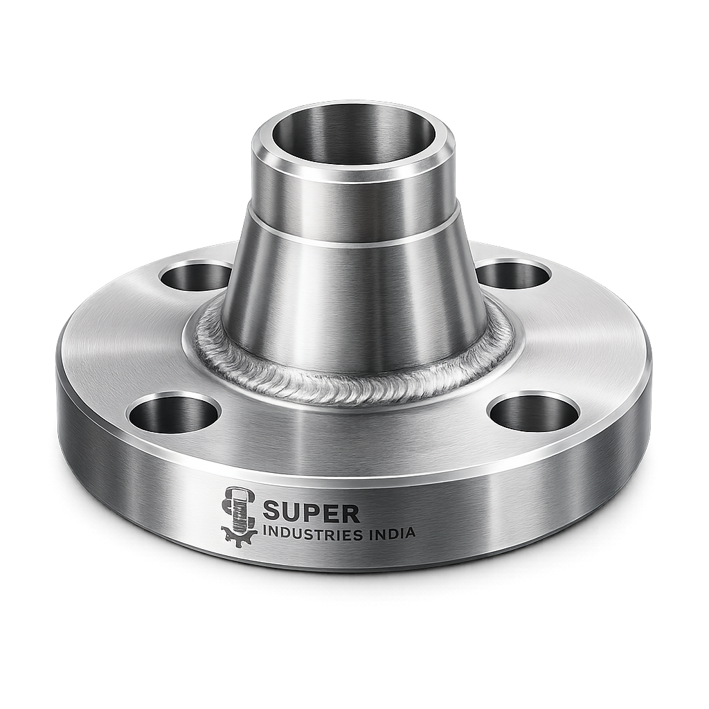
Role in High-Pressure Piping Systems
Weldo Flanges and Nipo Flanges are specialized integrally reinforced branch connection components used in pressure piping systems where structural integrity, compactness, and reduction of weld joints are critical design requirements.
In engineered piping networks, branch connections represent one of the most stress-sensitive locations due to:
- Discontinuity in pipe geometry
- Localized stress intensification
- Complex interaction of pressure, thermal, and mechanical loads
Traditional branch connections using fabricated tees or stub-in connections introduce:
- Multiple weld joints
- Heat-affected zones (HAZ)
- Increased inspection complexity
- Higher probability of fatigue initiation
Weldo and Nipo Flanges address these issues through integrated forging-based geometry, enabling:
- Reduced weld count
- Controlled stress distribution
- Improved fatigue performance
- Compact installation envelope
Functional Role of Branch Connection Integration
These flange configurations are designed to:
- Provide a pressure-rated flange interface for equipment or pipeline tie-ins
- Integrate a reinforced branch outlet directly into the flange body
- Eliminate the need for separate fittings such as:
- Weldolets
- Nipples
- Couplings
- Maintain compliance with pressure boundary requirements under ASME piping codes
Application Domains
Weldo Flanges and Nipo Flanges are used extensively in:
Oil & Gas Pipelines
- High-pressure transmission lines
- Pumping stations
- Pigging systems
Refineries
- Process units (hydrocrackers, distillation columns)
- Utility systems (steam, condensate)
- High-temperature hydrocarbon service
Petrochemical Plants
- Polymer processing lines
- Reactor feed systems
- Chemical transfer lines
Power Generation
- Boiler feedwater systems
- Steam distribution networks
- Turbine auxiliary piping
Offshore Platforms
- Space-constrained piping layouts
- Corrosion-prone marine environments
- High reliability requirements
LNG Terminals
- Cryogenic piping systems
- Low-temperature branch connections
- High integrity welded systems
Process Piping Networks
- Instrumentation take-offs
- Drain and vent systems
- Bypass and auxiliary connections
Engineering Rationale for Integrally Reinforced Branch Connections
Elimination of Fabricated Tees
Fabricated tees require:
- Multiple circumferential welds
- Reinforcement pads (repads)
- Complex NDT inspection
In contrast, Weldo/Nipo Flanges:
- Provide integral reinforcement
- Eliminate repads
- Reduce fabrication complexity
Reduction of Weld Joints
Each weld introduces:
- Metallurgical discontinuity
- Residual stress
- Potential defect location
By reducing weld count:
- Probability of failure decreases
- Inspection scope reduces
- Long-term reliability improves
Compact System Design
In congested piping layouts:
- Space optimization is critical
- Reduced component count improves accessibility
Weldo/Nipo Flanges provide:
- Combined functionality in a single component
- Reduced installation footprint
Structural Integrity Improvement
Forged, integrally reinforced components exhibit:
- Continuous grain flow
- Improved load-bearing capability
- Reduced stress concentration zones
This results in:
- Higher fatigue resistance
- Improved pressure containment
- Enhanced lifecycle performance
2. Technical Definition
Weldo Flange — Engineering Definition
A Weldo Flange is a forged branch connection component combining:
- A weld neck flange (WNRF)
- An integrally reinforced branch outlet (similar to a weldolet)
Key Characteristics:
- Designed for butt welding to the header pipe
- Branch outlet is integral to flange body
- Provides smooth stress transition between header and branch
- Available in:
- Straight outlet configuration
- Angled or offset branch designs (project-specific)
Structural Configuration
A typical Weldo Flange includes:
- Flange face (RF / RTJ)
- Hub (tapered neck)
- Reinforced branch outlet
- Bore aligned with header pipe
Functional Integration:
- Flange connects to mating flange or equipment
- Neck weld connects to header pipe
- Branch outlet connects to secondary pipeline
Nipo Flange — Engineering Definition
A Nipo Flange is a forged flange with an integrally machined nipple, used primarily for small bore branch connections.
Configuration:
- Flange body (ASME B16.5 compliant)
- Integral nipple extension
- Outlet termination options:
- Threaded (NPT / BSP)
- Socket weld (SW)
Functional Role of Nipo Flanges
Nipo Flanges are typically used for:
- Instrument connections
- Drain and vent points
- Small bore auxiliary lines
They eliminate the need for:
- Separate nipples
- Threaded couplings
- Additional welding operations
Comparison: Weldo vs Nipo Flanges
| Parameter | Weldo Flange | Nipo Flange |
|---|---|---|
| Outlet Type | Butt weld | Threaded / Socket weld |
| Branch Size | Medium to large | Small bore |
| Welding Requirement | Full penetration butt weld | Minimal (SW or threaded) |
| Application | High pressure, structural lines | Instrumentation / auxiliary |
| Reinforcement | Integrally reinforced | Moderate reinforcement |
| Stress Handling | High | Moderate |
Reinforced Outlet Geometry
Both flange types incorporate reinforcement contours designed to:
- Increase cross-sectional area at branch junction
- Reduce stress concentration
- Distribute loads over a wider region
Geometry features include:
- Smooth curvature transitions
- Controlled thickness distribution
- Optimized radius blending
Integration vs Fabricated Assemblies
Fabricated Assembly:
- Separate flange + weldolet/nipple
- Multiple welds
- Alignment challenges
Integrated Flange (Weldo/Nipo):
- Single forged component
- Minimal welds
- Improved dimensional accuracy
Super Industries
Global Manufacturer of Heavy & Custom Engineered Fasteners & Flanges
3. Engineering & Stress Distribution Principle
Stress Concentration at Branch Connections
Branch connections are inherently prone to:
- Localized stress amplification
- Disruption of hoop stress flow
- High stress intensity factors (SIFs)
Primary stress types include:
- Hoop stress (circumferential)
- Longitudinal stress (axial)
- Radial stress (internal pressure)
Internal Pressure Behavior
Under internal pressure:
- Pipe wall experiences uniform hoop stress
- Introduction of a branch creates:
- Material discontinuity
- Local thinning effect
This results in:
- Increased stress near branch opening
- Potential crack initiation zone
Reinforcement Area Concept (ASME B31.3)
To compensate for material removal due to branch opening:
- Reinforcement area must be added
Principle:
Area removed by branch opening must be replaced by reinforcement within a defined zone.
Sources of reinforcement:
- Excess wall thickness
- Branch fitting geometry
- Weld metal
Load Transfer Mechanism
In integrally reinforced fittings:
- Load is transferred through:
- Continuous metal structure
- Gradual thickness transition
This ensures:
- Reduced stress gradient
- Improved load distribution
Axial and Hoop Stress Interaction
At the branch junction:
- Hoop stress is interrupted
- Axial stress is redistributed
Weldo/Nipo designs ensure:
- Smooth transition of stress lines
- Avoidance of abrupt geometry changes
Weld Integrity vs Forged Integration
Welded Assemblies:
- Heat-affected zones (HAZ)
- Residual stresses
- Possible weld defects
Forged Integration:
- Uniform grain structure
- No weld discontinuities
- Improved metallurgical integrity
Crack Initiation and Propagation Control
Cracks typically initiate at:
- Weld toes
- Sharp geometric transitions
- High stress zones
Integrally reinforced flanges:
- Minimize sharp transitions
- Reduce weld exposure
- Improve fatigue life
Fatigue Resistance Mechanism
In cyclic loading conditions:
- Repeated stress leads to fatigue failure
Weldo/Nipo Flanges improve fatigue performance by:
- Reducing stress concentration
- Eliminating weld defects
- Maintaining uniform material structure
Structural Reliability Enhancement
Key contributors to reliability:
- Controlled forging process
- Optimized reinforcement geometry
- Reduced weld count
- Compliance with ASME design rules
4. Pressure & Load Engineering
Pressure Rating Classification
Weldo and Nipo Flanges are manufactured in accordance with:
- ASME pressure classes:
- Class 150
- Class 300
- Class 600
- Class 900
- Class 1500
- Class 2500
Pressure capacity depends on:
- Material grade
- Temperature
- Wall thickness
- Flange geometry
Branch Reinforcement Considerations
Design must ensure:
- Adequate reinforcement area
- Compliance with allowable stress limits
- Compatibility with header pipe thickness
Static vs Cyclic Loading
Static Loading:
- Internal pressure
- Dead weight
- Sustained loads
Cyclic Loading:
- Thermal expansion/contraction
- Pressure fluctuations
- Vibration
Design must account for:
- Fatigue life
- Stress range
- Load cycles
Thermal Expansion Effects
Temperature variations cause:
- Differential expansion between header and branch
- Induced thermal stresses
Proper design ensures:
- Flexibility in system
- Controlled stress distribution
Stress Intensification Factors (SIF)
Branch connections exhibit:
- Higher SIF compared to straight pipe
Weldo Flanges reduce SIF by:
- Providing reinforcement
- Smoothing stress flow
Burst Margin Philosophy
Design includes safety margin:
- Operating pressure << Burst pressure
Factors influencing burst margin:
- Material strength
- Wall thickness
- Manufacturing quality
Code Compliance Requirements
Design and manufacturing must comply with:
- Allowable stress limits
- Reinforcement requirements
- Dimensional tolerances
- Material traceability
Dimensional & Design Logic
Header Pipe vs Branch Size Relationship
Branch size selection depends on:
- Flow requirements
- Pressure drop considerations
- System layout
Typical ratio:
- Branch size ≤ Header size
Flange Class vs Wall Thickness
Higher pressure class → increased:
- Flange thickness
- Hub dimensions
- Reinforcement requirements
Hub Geometry
Hub design ensures:
- Smooth stress transition
- Proper weld profile
- Alignment with pipe bore
Bore Matching
Critical for:
- Flow efficiency
- Avoiding turbulence
- Maintaining pressure integrity
Facing Types
Raised Face (RF):
- General service
- Moderate pressure
Ring Type Joint (RTJ):
- High pressure / high temperature
- Metal-to-metal sealing
Dimensional Tolerances
Controlled as per:
- ASME B16.5
- MSS SP standards
Parameters include:
- Bore diameter tolerance
- Flange thickness tolerance
- Bolt hole alignment
Concentricity & Perpendicularity
Critical for:
- Proper flange alignment
- Uniform gasket compression
- Leak prevention
Design Integration Considerations
- Alignment with piping system
- Compatibility with mating components
- Ease of installation
- Inspection accessibility
5. Applicable Standards (ASTM / ASME / MSS / DIN / EN)
Weldo Flanges and Nipo Flanges are governed by a combination of dimensional, material, and design standards. Compliance is essential for acceptance in EPC projects, third-party inspection, and pressure boundary validation.
ASME B16.5 — Flange Dimensions & Ratings
Scope:
- Defines dimensions for flanges up to NPS 24
- Covers:
- Flange thickness
- Bolt circle diameter
- Number and size of bolt holes
- Facing types (RF, RTJ)
- Pressure-temperature ratings
Relevance to Weldo / Nipo Flanges:
- Governs the flange interface geometry
- Ensures interchangeability with mating flanges
- Defines pressure class rating framework
ASME B31.3 — Process Piping Design Code
Scope:
- Design, materials, fabrication, testing, and inspection of process piping
Critical Relevance:
- Branch reinforcement requirements
- Allowable stress limits
- Fatigue considerations
- Load combinations
Key Design Principle:
- Reinforcement area must compensate for material removed at branch opening
Weldo Flanges and Nipo Flanges are evaluated under:
- Pressure design criteria
- Stress intensification factors (SIF)
- Flexibility analysis inputs
MSS SP-97 — Integrally Reinforced Branch Fittings
Scope:
- Covers forged branch outlet fittings such as:
- Weldolets
- Sockolets
- Threadolets
Relevance:
- Provides guidance on:
- Reinforcement geometry
- Dimensional proportions
- Manufacturing practices
Weldo Flanges integrate this concept into a flanged configuration, extending MSS SP-97 principles.
ASTM Material Standards
Material selection and certification are governed by ASTM specifications, including:
- ASTM A105 — Carbon steel forgings (ambient temperature service)
- ASTM A350 LF2 — Low-temperature carbon steel
- ASTM A182 — Alloy and stainless steel forgings
These standards define:
- Chemical composition
- Mechanical properties
- Heat treatment conditions
- Testing requirements
DIN / EN Standards (Project-Specific)
For European or cross-standard projects:
- DIN EN 1092-1 — Flanges and dimensions
- EN 10222 — Forged steel materials
- DIN 2527 —Branch Connections
Used when:
- EPC specifications require EN compliance
- Cross-border projects demand dual certification
Standard Mapping to Engineering Functions
| Standard | Function | Application in Weldo/Nipo Flanges |
|---|---|---|
| ASME B16.5 | Dimensional & pressure rating | Flange interface geometry |
| ASME B31.3 | Design code | Reinforcement & stress validation |
| MSS SP-97 | Branch fitting geometry | Reinforced outlet design |
| ASTM Standards | Material properties | Mechanical integrity |
| DIN / EN | Alternate compliance | Export / European projects |
6. Material & Grade Options
Material selection for Weldo Flanges and Nipo Flanges is driven by:
- Pressure and temperature conditions
- Corrosion environment
- Fluid characteristics
- Project specifications
Carbon Steel Grades
ASTM A105
- Standard forging material for:
- Ambient temperature service
- Oil & gas pipelines
- Good machinability
- Moderate corrosion resistance
ASTM A350 LF2
- Designed for:
- Low-temperature applications
- Sub-zero service
- Improved notch toughness
Stainless Steel Grades
ASTM A182 F304
- General-purpose stainless steel
- Suitable for:
- Mild corrosive environments
- Process piping
ASTM A182 F316
- Contains molybdenum
- Improved resistance to:
- Chlorides
- Marine environments
- Chemical exposure
Alloy Steel Grades
ASTM A182 F11 / F22
- Used for:
- High-temperature service
- Power plants
- Steam lines
Characteristics:
- High creep resistance
- Elevated temperature strength
Duplex & Super Duplex Stainless Steel
- Dual-phase microstructure (austenitic + ferritic)
- High strength and corrosion resistance
Applications:
- Offshore platforms
- Seawater systems
- Aggressive chemical environments
Material Comparison Table
| Grade | Yield Strength (MPa) | Tensile Strength (MPa) | Temperature Range | Corrosion Resistance | Typical Application |
|---|---|---|---|---|---|
| ASTM A105 | ~250 | 485–620 | -29°C to 425°C | Low | General oil & gas |
| ASTM A350 LF2 | ~250 | 485–620 | -46°C to 345°C | Low | Low-temperature pipelines |
| ASTM A182 F304 | ~205 | 515–720 | -196°C to 870°C | Moderate | Process piping |
| ASTM A182 F316 | ~205 | 515–720 | -196°C to 870°C | High | Marine / chemical |
| ASTM A182 F11 | ~275 | 415–585 | Up to 540°C | Moderate | Power plants |
| ASTM A182 F22 | ~415 | 585–760 | Up to 600°C | Moderate | High-temp steam |
| Duplex SS | ~450 | 620–880 | -50°C to 300°C | Very High | Offshore |
| Super Duplex | ~550 | 750–950 | -50°C to 300°C | Excellent | Seawater systems |
7. Heat Treatment Information
Heat treatment is critical for achieving:
- Required mechanical properties
- Microstructural stability
- Compliance with ASTM standards
Normalizing
- Heating above critical temperature
- Air cooling
Effects:
- Refines grain structure
- Improves toughness
- Enhances uniformity
Quenching & Tempering (Q&T)
- Rapid cooling (quenching)
- Followed by controlled reheating (tempering)
Benefits:
- Increased strength
- Improved ductility
- Controlled hardness
Stress Relieving
- Heating below transformation temperature
- Reduces residual stresses
Importance:
- Prevents distortion
- Improves dimensional stability
Solution Annealing (For Stainless Steel)
- Heating to high temperature
- Rapid quenching
Purpose:
- Dissolves carbides
- Improves corrosion resistance
Hardness Ranges (Typical)
| Material | Hardness (HB) |
|---|---|
| A105 | 137–187 |
| LF2 | 130–187 |
| F304 | ≤ 201 |
| F316 | ≤ 217 |
| F22 | 170–220 |
Impact Testing (Charpy V-Notch)
Required for:
- Low-temperature service
- Critical applications
Ensures:
- Resistance to brittle fracture
- Compliance with project specifications
8. Manufacturing Process
Weldo Flanges and Nipo Flanges are manufactured through a controlled forging and machining process ensuring pressure-boundary integrity.
Raw Material Inspection
- Verification of:
- Heat number
- Chemical composition
- Mechanical properties
- PMI (Positive Material Identification) conducted
Closed-Die Forging
- Material heated to forging temperature
- Shaped under high pressure
Advantages:
- Continuous grain flow
- High structural integrity
- Elimination of internal voids
Branch Integration Forming
- Reinforced outlet formed during forging stage
- Geometry optimized for:
- Load transfer
- Stress distribution
CNC Machining
- Precision machining of:
- Flange faces
- Bolt holes
- Bore diameter
- Hub geometry
Tolerance control:
- As per ASME B16.5
Bore Finishing
- Ensures smooth internal surface
- Minimizes turbulence
- Maintains dimensional accuracy
Facing Machining
- RF serrations or RTJ grooves machined
Surface finish:
- Typically 125–250 AARH (Ra equivalent)
Heat Treatment
Applied as per:
- Material specification
- Project requirement
Surface Finishing
- Coating or treatment applied based on service environment
Marking & Traceability
Each flange marked with:
- Material grade
- Heat number
- Size and pressure class
- Manufacturer identification
Ensures:
- Full traceability
- Inspection compliance
Surface Finish Options
Surface finish selection depends on:
- Corrosion environment
- Storage conditions
- Project requirements
Anti-Rust Coating
- Temporary protection during storage and transport
Zinc Plating
- Provides corrosion resistance
- Suitable for mild environments
Hot Dip Galvanizing (HDG)
- Thick zinc coating
- Suitable for outdoor exposure
PTFE Coating
- Chemical resistance
- Low friction surface
Black Oxide
- Minimal corrosion protection
- Used for controlled environments
Passivation (Stainless Steel)
- Removes free iron
- Enhances corrosion resistance
Surface Roughness & Flange Face Finish
Flange sealing performance depends on:
- Surface roughness (Ra)
- Serration pattern
Typical RF finish:
- 3.2–6.3 µm Ra
RTJ finish:
- Smooth groove with tight tolerances
9. Inspection & Quality Control Methods
Weldo Flanges and Nipo Flanges are pressure-boundary components and are subjected to multi-stage inspection protocols to ensure compliance with EPC specifications and international standards.
Positive Material Identification (PMI)
- Confirms alloy composition using:
- XRF (X-ray fluorescence)
- OES (Optical emission spectroscopy)
Purpose:
- Prevents material mix-up
- Ensures compliance with ASTM grade
Ultrasonic Testing (UT)
- Detects internal discontinuities:
- Voids
- Inclusions
- Laminations
Applicable for:
- Forged components
- High-pressure applications
Magnetic Particle Inspection (MPI)
- Surface and near-surface defect detection
- Applicable for ferromagnetic materials
Detects:
- Cracks
- Seams
- Laps
Dye Penetrant Inspection (DPI / PT)
- Used for:
- Stainless steel
- Non-magnetic alloys
Detects:
- Surface cracks
- Porosity
Dimensional Inspection
Verification against:
- ASME B16.5 tolerances
- Project drawings
Includes:
- Flange OD
- Bolt circle diameter
- Bore diameter
- Hub dimensions
- Branch alignment
Hardness Testing
- Brinell or Rockwell methods
Ensures:
- Compliance with material specifications
- Proper heat treatment
Hydrostatic Testing (If Applicable)
- Performed for critical applications
- Validates pressure integrity
Third-Party Inspection (TPI)
Conducted by:
- Independent inspection agencies
Scope includes:
- Witnessing tests
- Document verification
- Final release inspection
Certification
- EN 10204 3.1 — Manufacturer test certificate
- EN 10204 3.2 — Third-party validated certificate
Includes:
- Chemical analysis
- Mechanical properties
- Heat treatment records
A. DIMENSIONAL TABLE (REFERENCE FORMAT)
Indicative values. Final dimensions per ASME B16.5 and project drawings.
| Header Size (NPS) | Branch Size (NPS) | Flange Class | Bore (mm) | Hub Dia (mm) | Thickness (mm) |
|---|---|---|---|---|---|
| 4″ | 2″ | 300 | 102 | 140 | 24 |
| 6″ | 3″ | 300 | 154 | 190 | 28 |
| 8″ | 4″ | 600 | 203 | 240 | 38 |
| 10″ | 6″ | 600 | 254 | 290 | 45 |
| 12″ | 8″ | 900 | 305 | 350 | 60 |
B. PRESSURE RATING TABLE (ASME B16.5 REFERENCE)
Approximate allowable pressure (bar) at temperature
| Class | 38°C | 200°C | 400°C |
|---|---|---|---|
| 150 | 19.6 | 15.3 | 6.8 |
| 300 | 51.1 | 40.0 | 17.8 |
| 600 | 102.1 | 80.1 | 35.6 |
| 900 | 153.2 | 120.2 | 53.4 |
| 1500 | 255.3 | 200.3 | 89.0 |
| 2500 | 425.5 | 333.8 | 148.3 |
C. TORQUE CHART
Torque values depend on:
- Bolt material
- Lubrication condition
- Gasket type
Indicative Torque Values (Nm)
| Bolt Size | Grade B7 (Dry) | Grade B7 (Lubricated) | Grade 8.8 | Grade 10.9 |
|---|---|---|---|---|
| M16 | 210 | 160 | 200 | 290 |
| M20 | 410 | 310 | 390 | 560 |
| M24 | 710 | 530 | 680 | 960 |
| M30 | 1420 | 1060 | 1350 | 1900 |
| M36 | 2480 | 1860 | 2350 | 3300 |
Bolt Tightening Sequence
- Cross-pattern tightening
- Multi-stage torque application:
- 30% → 60% → 100%
Ensures:
- Uniform gasket compression
- Leak-free sealing
D. REINFORCEMENT CALCULATION GUIDE
Area Replacement Principle (ASME B31.3)
The required reinforcement area is based on:
Area removed by the branch opening must be compensated by available reinforcement.
General Formula
Required reinforcement area:

Where:
- ( d ) = diameter of branch opening
- ( t ) = required wall thickness of header
Available Reinforcement Area

Where:
- ( A_1 ) = excess thickness in header
- ( A_2 ) = excess thickness in branch
- ( A_3 ) = reinforcement from fitting
Acceptance Condition

Sample Calculation
Given:
- Header thickness = 12 mm
- Required thickness = 10 mm
- Branch diameter = 100 mm

Available reinforcement:
- Header excess:

Remaining requirement fulfilled by:
- Weldo flange reinforcement geometry
Engineering Interpretation
- Reinforcement must be located within defined limits
- Integrally forged fittings provide built-in compliance
- Eliminates need for external reinforcement pads
E. MECHANICAL PROPERTY TABLE
| Material | Yield Strength (MPa) | Tensile Strength (MPa) | Elongation (%) | Hardness (HB) |
|---|---|---|---|---|
| A105 | 250 | 485–620 | 22 | 137–187 |
| LF2 | 250 | 485–620 | 22 | 130–187 |
| F304 | 205 | 515–720 | 30 | ≤ 201 |
| F316 | 205 | 515–720 | 30 | ≤ 217 |
| F22 | 415 | 585–760 | 20 | 170–220 |
| Duplex | 450 | 620–880 | 25 | 250–300 |
F. CORROSION RESISTANCE TABLE
| Material | Marine | Chemical | Hydrocarbon | High Temperature |
|---|---|---|---|---|
| Carbon Steel | Poor | Poor | Good | Moderate |
| SS304 | Moderate | Good | Good | Good |
| SS316 | Good | Very Good | Good | Good |
| Alloy Steel | Poor | Moderate | Excellent | Excellent |
| Duplex | Excellent | Excellent | Excellent | Moderate |
| Super Duplex | Outstanding | Outstanding | Excellent | Moderate |
10. ENGINEERING PERFORMANCE INSIGHT
Reliability vs Fabricated Connections
| Parameter | Fabricated Tee | Weldo/Nipo Flange |
|---|---|---|
| Weld Count | High | Low |
| Stress Concentration | High | Reduced |
| Inspection Complexity | High | Moderate |
| Fatigue Life | Lower | Higher |
Failure Risk Reduction
Integrally reinforced flanges reduce:
- Weld failure probability
- HAZ-related cracking
- Alignment-induced stress
Inspection Efficiency
Reduced welds → reduced NDT scope → improved inspection turnaround
Lifecycle Performance
- Lower maintenance requirement
- Reduced leakage probability
- Improved operational stability
Engineering Validation
Weldo and Nipo Flanges are validated through:
- Code compliance (ASME B31.3)
- Dimensional standards (ASME B16.5)
- Material certification (ASTM)
- Inspection protocols (NDT + TPI)
11. Industries Served
Weldo Flanges and Nipo Flanges are deployed in critical pressure systems across multiple industries where branch connection integrity directly impacts system safety and uptime.
Oil & Gas Sector
Upstream (Exploration & Production)
- Wellhead piping systems
- High-pressure flowlines
- Injection systems
Engineering Requirement:
- Resistance to cyclic pressure loading
- High reliability under variable flow conditions
- Compact branch configurations in skid-mounted systems
Midstream (Transportation & Storage)
- Cross-country pipelines
- Pumping and compression stations
- Metering skids
Application of Weldo/Nipo Flanges:
- Instrumentation take-offs
- Drain and vent connections
- Bypass lines
Downstream (Refining & Processing)
- Hydroprocessing units
- Crude and vacuum distillation
- Reforming and cracking units
Requirement:
- High temperature resistance
- Corrosion resistance (sulfur, hydrocarbons)
- Reduced weld inspection scope
Refineries
Used in:
- Process piping networks
- Utility systems (steam, condensate, cooling water)
- Tank farms and transfer systems
Engineering Justification:
- Minimization of weld joints in hazardous zones
- Improved fatigue resistance in thermal cycling systems
Petrochemical Plants
Applications include:
- Reactor feed systems
- Polymer processing lines
- Chemical transfer piping
Material Considerations:
- Stainless steel (F304 / F316)
- Duplex grades for aggressive chemicals
Power Generation Plants
Thermal Power Plants
- Boiler feedwater systems
- High-pressure steam lines
Combined Cycle Plants
- Gas turbine auxiliary piping
- Heat recovery steam generator (HRSG) systems
Material Preference:
- Alloy steels (F11 / F22) for high-temperature service
LNG & Cryogenic Systems
- Liquefaction plants
- LNG storage and regasification
Key Requirements:
- Low-temperature toughness (ASTM A350 LF2, SS grades)
- Leak-tight performance
- Structural integrity under thermal contraction
Offshore & Marine Installations
- FPSO units
- Offshore platforms
- Subsea piping modules
Engineering Constraints:
- Space limitation
- High corrosion exposure
- Maintenance accessibility
Preferred Materials:
- Duplex / Super Duplex stainless steel
Process & Industrial Piping Systems
- Instrumentation connections
- Utility lines
- Drain and vent systems
Nipo Flanges are commonly used where:
- Small bore connections are required
- Threaded or socket weld outlets are preferred
12. Export Capability & Global Supply
Super Industries operates as a Weldo Flanges manufacturer and Nipo Flanges supplier for international EPC and industrial projects, with supply aligned to global documentation and logistics requirements.
Export Regions
Supply executed to:
- United States
- Europe
- Middle East
- Southeast Asia
- Africa (project-based supply)
Packaging Standards
Export packaging is designed to prevent:
- Mechanical damage
- Corrosion during transit
- Dimensional distortion
Packaging Methods:
- Wooden crates (fumigated as per ISPM-15)
- Palletized packing
- Individual flange protection (plastic caps / covers)
- Moisture barrier wrapping
Documentation Package
Each shipment includes:
Material Documentation
- Mill Test Certificate (MTC) as per EN 10204 3.1 / 3.2
- Chemical composition report
- Mechanical property report
Inspection Documentation
- NDT reports (UT / MPI / DPI)
- Dimensional inspection reports
- Hardness test reports
Compliance Documentation
- Conformance to ASME / ASTM standards
- Heat treatment records
- Traceability records
Project Logistics Handling
- Batch-wise traceability maintained
- Tagging aligned with project numbering systems
- Segregation by:
- Material grade
- Size
- Pressure class
Supports:
- EPC warehouse management
- Site identification and installation
13. Procurement & Installation View
Welding Procedures (Weldo Flanges)
- Butt welding to header pipe
- Welding procedure qualification (WPS/PQR) required
Key Controls:
- Preheat temperature (material dependent)
- Interpass temperature
- Weld consumable compatibility
Nipo Flange Installation
Threaded Connection:
- Sealant or PTFE tape applied
- Torque control to avoid thread damage
Socket Weld Connection:
- Controlled root gap (~1.5 mm typical)
- Fillet weld applied
Bolt Tightening Practices
- Use calibrated torque wrench
- Follow cross-pattern tightening
- Multi-stage tightening (30–60–100%)
Ensures:
- Uniform gasket compression
- Leak-free joint
Gasket Selection
Dependent on:
- Pressure class
- Temperature
- Fluid type
Common Types:
- Spiral wound gaskets (SWG)
- Ring Type Joint (RTJ) gaskets
- Non-asbestos sheet gaskets
Inspection Checkpoints (Site Level)
- Visual inspection of flange faces
- Verification of marking and traceability
- Alignment check before bolting
- Bolt torque verification
Storage & Handling
- Store in dry environment
- Avoid flange face damage
- Use protective covers
Custom Engineering Capabilities
Super Industries supports project-specific customization for Weldo and Nipo Flanges to meet EPC and consultant-driven requirements.
Non-Standard Branch Configurations
- Offset branch angles
- Unequal header-to-branch ratios
- Special reinforcement profiles
High-Pressure Custom Designs
- Class 1500 / 2500 configurations
- Thick wall header integration
- Enhanced reinforcement zones
Material Customization
- Duplex / Super Duplex
- Low-temperature carbon steel
- High alloy steels
Project-Specific Marking
- Client logo
- Tag numbers
- Heat number traceability
- Barcode / QR-based identification (if required)
Surface Coating Requirements
- Project-specific coating systems
- Offshore-grade coatings
- Chemical-resistant coatings
Engineering Conclusion
Weldo Flanges and Nipo Flanges are engineered branch connection solutions designed to meet the requirements of high-integrity pressure piping systems.
From an engineering standpoint:
- They provide integral reinforcement aligned with ASME B31.3 design principles
- They reduce weld count, thereby minimizing:
- Inspection scope
- Heat-affected zones
- Failure probability
- Their forged construction ensures:
- Continuous grain flow
- Improved stress distribution
- Enhanced fatigue resistance
- Dimensional compliance with ASME B16.5 ensures:
- Interchangeability
- Standardized installation
- Material selection as per ASTM standards ensures:
- Mechanical reliability
- Suitability across temperature and corrosion conditions
Final Engineering Assessment
From an EPC and consultant evaluation perspective:
- The use of Weldo Flanges and Nipo Flanges supports:
- Simplified fabrication
- Reduced lifecycle risk
- Improved inspection efficiency
- Integrally reinforced geometry provides:
- Compliance with reinforcement area requirements
- Structural reliability under pressure and thermal loads
Procurement Positioning
For technical evaluation:
- Classified as:
- ASME B16.5 Weldo Flange
- Branch connection flange fitting
- Nipo Flanges supplier component
- Suitable for:
- High-pressure systems
- Critical service applications
- Global EPC projects