
EN 1092-1 FLANGES
Super Industries
“Global Manufacturer of Heavy & Custom Engineered Fasteners for Oil & Gas, Power & EPC Contractors.”
1. Industry Context & System Relevance
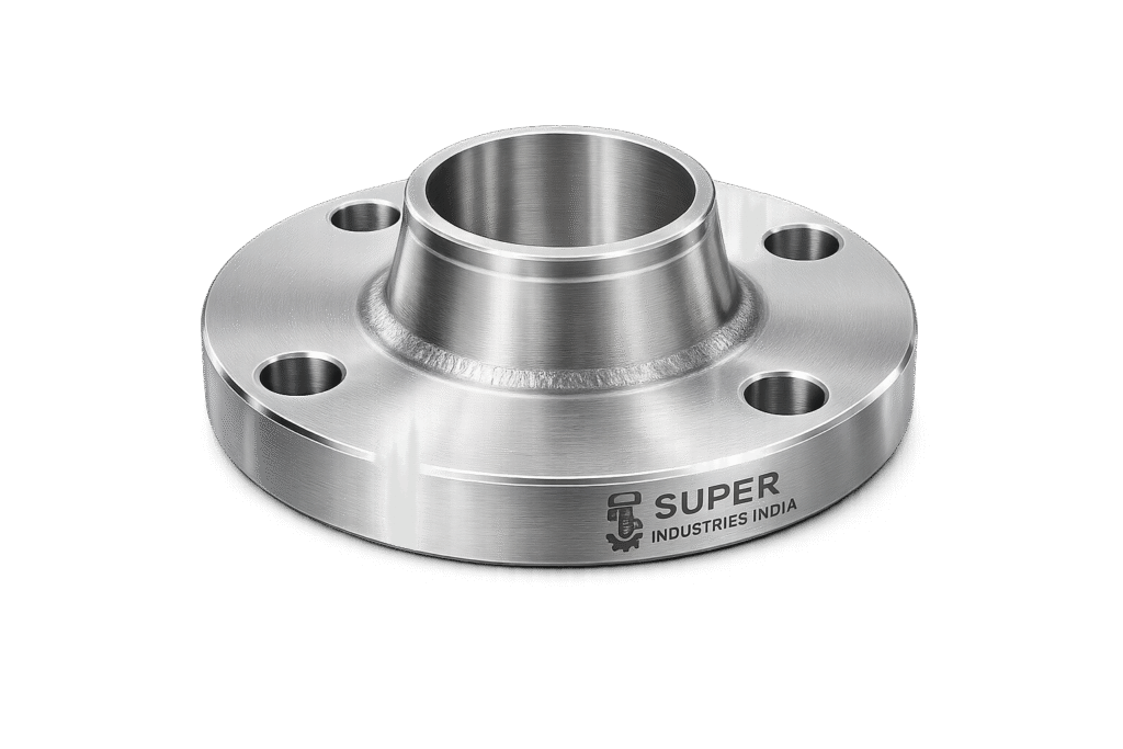
Role of EN 1092-1 Flanges in Pressure Piping Systems
EN 1092-1 Flanges are a fundamental component in European-standard pressure piping systems, providing a demountable, bolted joint interface between piping elements, valves, equipment nozzles, and pressure-retaining components.
Unlike welded joints, which are permanent, or threaded joints, which are limited in pressure and size, flanged joints provide:
- Controlled sealing via gasket compression
- Repeatable assembly and disassembly
- Inspection accessibility
- Alignment flexibility during installation
These characteristics make EN 1092-1 Flanges essential in systems where maintenance, inspection, and operational flexibility are required.
Application Across Industrial Sectors
Oil & Gas (Onshore & Offshore – European Compliance)
- Pipeline manifolds
- Pump and compressor connections
- Offshore platform piping systems
- Subsea-to-topside transition systems
EN 1092-1 compliance is often specified for European-origin EPC projects and offshore assets governed by PED.
Refineries & Petrochemical Plants
- High-temperature hydrocarbon processing lines
- Catalyst handling systems
- Fractionation units
Flanged joints allow periodic shutdown inspection without destructive dismantling.
Power Generation
- Steam lines (high pressure / high temperature)
- Boiler feedwater systems
- Turbine auxiliary piping
Critical requirement: creep resistance and thermal fatigue management
Water Treatment & Desalination
- Large-diameter, low-to-medium pressure pipelines
- Pump stations and filtration systems
Preferred due to ease of maintenance and corrosion protection options
LNG Terminals
- Cryogenic piping connections
- Loading/unloading arms
- Storage tank interfaces
Material selection (e.g., stainless and duplex) becomes critical for low-temperature performance
Chemical Processing Plants
- Acid and solvent transport lines
- Reactor connections
Flanges enable frequent maintenance cycles and chemical compatibility control
Infrastructure Piping Networks
- District cooling/heating systems
- Municipal water pipelines
- Industrial utility systems
Flanged systems allow modular expansion and replacement
Why Flanged Joints Are Preferred
1. Maintenance Accessibility
- Bolted joints allow removal without cutting or welding
- Enables rapid replacement of valves, pumps, and instruments
2. Inspection Capability
- Gasket surfaces can be visually inspected
- Bolt integrity can be verified
- Alignment issues can be corrected
3. Operational Flexibility
- Supports system modifications and upgrades
- Suitable for temporary installations
4. High Pressure & Temperature Suitability
- When properly designed, flanged joints sustain:
- High internal pressure
- Thermal cycling
- Mechanical vibration
Super Industries
Global Manufacturer of Heavy & Custom Engineered Fasteners & Flanges
2. Technical Definition of EN 1092-1 Flanges
Standard Overview
EN 1092-1 defines circular steel flanges for pipes, valves, fittings, and accessories, covering:
- Dimensions
- Pressure ratings (PN system)
- Materials
- Tolerances
- Facing types
It is aligned with European Pressure Equipment Directive (PED 2014/68/EU) requirements.
Core Functional Definition
An EN 1092-1 flange is:
A circular mechanical component with bolt holes, designed to connect piping elements using bolting and a gasket to achieve a pressure-tight seal.
Primary Functional Elements
- Flange body – load-bearing structure
- Bolt holes – mechanical fastening interface
- Sealing face – gasket contact surface
- Hub (if applicable) – stress distribution and weld interface
Flange Types (EN 1092-1 Classification)
Type 01 – Plate Flanges
- Flat plate with bore
- Used with slip-on pipe welding
- Suitable for low to moderate pressure
Type 02 – Slip-On Flanges
- Mounted over pipe and fillet welded
- Lower stress resistance compared to weld neck
Type 11 – Weld Neck Flanges
- Tapered hub with butt weld connection
- Designed for:
- High pressure
- High temperature
- Cyclic loading
Provides uniform stress distribution
Type 05 – Blind Flanges
- No bore
- Used to close pipeline ends
- Withstand full system pressure
Type 13 – Threaded Flanges
- Internal threads
- No welding required
- Limited to low-pressure applications
Lap Joint Flanges (Type 02/32 Combination)
- Used with stub ends
- Allows rotational alignment
- Suitable for systems requiring frequent dismantling
Pressure Rating System (PN System)
EN 1092-1 uses PN (Pressure Nominal) classification:
| PN Rating | Approx. Pressure (Bar) |
|---|---|
| PN6 | 6 bar |
| PN10 | 10 bar |
| PN16 | 16 bar |
| PN25 | 25 bar |
| PN40 | 40 bar |
| PN63 | 63 bar |
| PN100 | 100 bar |
Important:
Actual allowable pressure depends on:
- Material
- Temperature
- Design conditions
Nominal Diameter (DN System)
- DN represents approximate internal pipe diameter
- Defined in millimeters
Examples:
- DN50 ≈ 2 inch
- DN100 ≈ 4 inch
- DN300 ≈ 12 inch
Facing Types
Flat Face (FF)
- Full face contact
- Used with soft gaskets
- Common in low-pressure systems
Raised Face (RF)
- Raised sealing surface
- Concentrates gasket load
- Most widely used configuration
Tongue & Groove (TG)
- Interlocking faces
- Improved gasket alignment
Ring Type Joint (RTJ) (Limited Use in EN)
- Metal-to-metal sealing
- High pressure / critical service
3. Engineering & Sealing Principles
Fundamental Sealing Mechanism
A flanged joint achieves sealing through:
- Bolt preload
- Gasket compression
- Resistance to internal pressure
Bolt Preload Mechanics
When bolts are tightened:
- Tensile force develops in the bolt
- Compressive force is applied to the gasket
- Flanges are pulled together
This preload must be sufficient to:
- Seat the gasket
- Prevent leakage under pressure
Gasket Compression Behavior
The gasket acts as a deformable sealing element:
- Initially compressed during tightening
- Fills surface irregularities
- Maintains contact under pressure
Two key parameters:
- Seating stress (initial compression requirement)
- Operating stress (required to maintain seal under pressure)
Sealing Stress vs Internal Pressure
Internal pressure attempts to:
- Separate the flange faces
- Reduce gasket compression
- Cause leakage
Therefore:
Bolt preload must exceed the separating force generated by internal pressure.
Bolt Load vs Internal Pressure Interaction
The joint must satisfy:
- Bolt force ≥ pressure-induced separating force
- Residual gasket stress ≥ minimum sealing stress
If not:
- Leakage initiates
- Progressive joint failure may occur
Flange Rotation & Deflection
Under bolt load:
- Flanges tend to rotate outward (hinge effect)
- This reduces gasket stress at the inner diameter
Design considerations:
- Flange thickness
- Hub geometry (for weld neck)
- Bolt distribution
Flange Face Finish Influence
Surface roughness affects sealing performance:
| Finish Type | Ra Value (Typical) | Application |
|---|---|---|
| Smooth | < 3.2 µm | Metal gaskets |
| Serrated | 3.2 – 6.3 µm | Soft gaskets |
| Stock finish | ~6.3 µm | General use |
Too smooth → poor gasket grip
Too rough → gasket damage
Leakage Prevention Mechanism
A leak-tight joint requires:
- Uniform bolt loading
- Proper gasket selection
- Correct flange alignment
- Controlled surface finish
Gasket Seating Stress Theory
Initial bolt tightening must:
- Generate seating stress greater than gasket minimum requirement
- Ensure full contact across sealing surface
After pressurization:
- Remaining stress must exceed minimum operating stress
Thermal & Mechanical Influences
Thermal Expansion
- Differential expansion between bolts and flanges
- Can reduce preload
Cyclic Loading
- Causes fatigue in bolts
- Leads to relaxation of preload
Creep (High Temperature)
- Material deformation over time
- Reduces gasket compression
Engineering Control Measures
- Use of proper bolt materials (e.g., high-strength classes)
- Controlled torque application
- Use of hardened washers
- Periodic inspection in critical systems
Summary of Engineering Role
EN 1092-1 Flanges function as:
- A mechanical connector
- A pressure-retaining sealing system
- A maintenance-access interface
Their performance depends on:
- Proper design selection
- Material compatibility
- Controlled installation practices
- Compliance with European standards
4. Applicable Standards & Compliance Framework
EN 1092-1 Flanges are not standalone components; they operate within a multi-standard compliance structure governing design, materials, testing, and certification. For EPC project evaluation, understanding how these standards interrelate is essential.
EN 1092-1 (Primary Standard)
Defines:
- Flange dimensions (DN range, thickness, PCD, bolt holes)
- Pressure classes (PN system)
- Facing types (FF, RF, TG)
- Tolerances and marking
Engineering Relevance:
- Ensures dimensional interchangeability across European projects
- Establishes baseline geometry for pressure integrity
Material Standards
EN 10222 (Forged Steel for Pressure Purposes)
Applicable for forged flanges such as:
- Weld neck (Type 11)
- Blind flanges (Type 05, forged)
Defines:
- Mechanical properties
- Heat treatment conditions
- Chemical composition
EN 10273 (Hot Rolled Bars for Pressure Equipment)
Applicable for:
- Plate flanges (Type 01)
- Machined-from-bar components
EN 10204 (Inspection Documentation)
Defines certification levels:
| Certificate Type | Description |
|---|---|
| 2.1 | Declaration of compliance |
| 2.2 | Test report (non-specific) |
| 3.1 | Mill test certificate (traceable to batch) |
| 3.2 | Third-party witnessed certification |
EPC Requirement:
- Minimum: EN 10204 3.1
- Critical service: 3.2 with TPI involvement
Pressure Equipment Directive (PED 2014/68/EU)
Mandatory for equipment supplied to the European Economic Area.
Defines:
- Conformity assessment procedures
- CE marking requirements
- Hazard categorization (fluid group, pressure, volume)
Flange Relevance:
- Must be manufactured under PED-compliant quality systems
- Material traceability and testing are mandatory
ASTM / ASME Equivalence (Global Projects)
In multinational EPC projects, EN flanges are often compared with:
| EN Standard | Approximate Equivalent |
|---|---|
| EN 1092-1 | ASME B16.5 / B16.47 |
| P250GH | ASTM A105 |
| 1.4404 | ASTM A182 F316L |
Important Engineering Note:
- EN PN ratings ≠ ASME Class ratings
- Direct substitution requires:
- Pressure-temperature validation
- Dimensional compatibility checks
Standard Mapping to Engineering Decisions
| Engineering Parameter | Governing Standard |
|---|---|
| Dimensions | EN 1092-1 |
| Material properties | EN 10222 / EN 10273 |
| Certification | EN 10204 |
| Regulatory compliance | PED 2014/68/EU |
| Global compatibility | ASTM / ASME |
5. Material & Grade Selection
Material selection for EN 1092-1 Flanges is driven by:
- Operating pressure
- Temperature
- Corrosion environment
- Fluid composition
- Project specifications
Carbon Steel Grades
P245GH / P250GH
- Widely used in pressure equipment
- Good weldability
- Suitable for moderate temperature service
C22.8 (1.0460)
- Forged steel grade
- Higher mechanical strength than plate grades
- Common for forged flanges
Stainless Steel Grades
1.4301 (AISI 304)
- General corrosion resistance
- Suitable for water and mild chemical service
1.4401 / 1.4404 (AISI 316 / 316L)
- Improved resistance to chlorides
- Suitable for marine and chemical environments
Duplex & Super Duplex Stainless Steel
1.4462 (Duplex)
- High strength (~2× austenitic stainless steel)
- Good resistance to stress corrosion cracking
1.4410 (Super Duplex)
- Enhanced corrosion resistance
- Suitable for offshore and aggressive environments
Alloy Steel Grades
13CrMo4-5
- Elevated temperature service
- Used in boilers and pressure vessels
10CrMo9-10
- High creep resistance
- Suitable for high-pressure steam lines
Material Selection Considerations
| Parameter | Material Influence |
|---|---|
| High temperature | Alloy steels (Cr-Mo grades) |
| Corrosive fluids | Stainless / Duplex |
| High pressure | Forged carbon steel / duplex |
| Cryogenic service | Austenitic stainless steel |
Mechanical & Service Property Table
| Grade | Yield Strength (MPa) | Tensile Strength (MPa) | Temperature Range (°C) | Corrosion Resistance | Typical Use |
|---|---|---|---|---|---|
| P245GH | ~245 | 410–530 | -10 to 450 | Low | General pressure systems |
| P250GH | ~250 | 410–530 | -10 to 450 | Low | Boilers, pipelines |
| C22.8 | ~240 | 450–600 | -20 to 450 | Low | Forged flanges |
| 1.4301 (304) | ~215 | 500–700 | -196 to 600 | Moderate | Water, food |
| 1.4404 (316L) | ~170 | 485–620 | -196 to 600 | High | Chemical, marine |
| 1.4462 Duplex | ~450 | 620–880 | -50 to 300 | Very High | Offshore, oil & gas |
| 1.4410 Super Duplex | ~550 | 750–950 | -50 to 300 | Extreme | Seawater systems |
| 13CrMo4-5 | ~280 | 450–600 | Up to 570 | Moderate | Boilers |
| 10CrMo9-10 | ~300 | 480–650 | Up to 600 | Moderate | High-temp piping |
6. Heat Treatment Processes
Heat treatment ensures that flange materials achieve required mechanical properties and microstructural stability.
Normalizing
- Heating above critical temperature (~900°C)
- Air cooling
Effect:
- Refines grain structure
- Improves toughness
- Reduces internal stress
Quenching & Tempering (Q&T)
- Rapid cooling (quenching) followed by reheating (tempering)
Effect:
- High strength
- Controlled hardness
- Improved fatigue resistance
Solution Annealing (Stainless Steel)
- Heating to ~1050–1100°C
- Rapid cooling
Effect:
- Dissolves carbides
- Restores corrosion resistance
- Improves ductility
Stress Relieving
- Heating below transformation temperature (~550–650°C)
Effect:
- Reduces residual stresses from machining or welding
Hardness & Mechanical Control
| Material Type | Typical Hardness (HB) |
|---|---|
| Carbon steel | 120–180 HB |
| Alloy steel (Q&T) | 180–250 HB |
| Stainless steel | 150–220 HB |
| Duplex | 250–320 HB |
Impact Testing (Charpy V-Notch)
- Conducted at specified temperatures
- Measures material toughness
Critical for:
- Low-temperature service
- Offshore applications
Microstructural Considerations
| Material | Microstructure |
|---|---|
| Carbon steel | Ferrite + Pearlite |
| Stainless (austenitic) | Austenite |
| Duplex | Austenite + Ferrite |
| Alloy steel | Tempered martensite |
7. Manufacturing Process
The manufacturing of EN 1092-1 Flanges follows a controlled, traceable, and inspection-driven sequence.
Raw Material Verification
- Material test certificate review (EN 10204 3.1)
- Heat number verification
- Chemical composition check
Forging / Plate Cutting
Forged Flanges:
- Billet heating
- Open-die or closed-die forging
Plate Flanges:
- CNC or profile cutting from plates
Objective:
- Achieve required grain flow and structural integrity
Heat Treatment (Post-Forging)
- Normalizing or Q&T as required
- Ensures uniform mechanical properties
CNC Machining
- Bore machining (ID)
- Outer diameter turning
- Facing surface preparation
Critical Parameters:
- Dimensional accuracy
- Surface finish (Ra control)
Bolt Hole Drilling
- CNC drilling for positional accuracy
- Equal spacing along PCD
Engineering Requirement:
- Angular tolerance control
- Hole perpendicularity
Facing Machining
- Serrated or smooth finish generation
- Controlled Ra values
Surface Finishing
Depending on material and application:
- Shot blasting
- Passivation (for stainless steel)
- Coating or galvanizing
Final Inspection
- Dimensional verification
- Surface finish inspection
- Marking verification
Marking & Traceability
Each flange is marked with:
- Manufacturer identification
- Material grade
- PN rating
- DN size
- Heat number
- Standard reference (EN 1092-1)
Ensures full traceability from raw material to final installation
Packaging
- Wooden crates / pallets
- Anti-corrosion protection
- Face protection covers
8. Surface Finish & Protection Options
Coating Options
| Finish Type | Application |
|---|---|
| Anti-rust oil | Temporary protection |
| Black painting | General industrial use |
| Zinc plating | Corrosion resistance (low thickness) |
| Hot-dip galvanizing | Long-term outdoor protection |
| Passivation (SS) | Corrosion resistance restoration |
Sealing Face Roughness (Ra Values)
| Gasket Type | Recommended Ra |
|---|---|
| Soft gasket | 3.2 – 6.3 µm |
| Spiral wound | 3.2 – 6.3 µm |
| Metal gasket | < 3.2 µm |
Engineering Importance
- Proper roughness ensures gasket grip
- Prevents micro-leakage paths
- Maintains sealing under pressure
A. Dimensional Reference Tables (EN 1092-1)
Dimensional control is critical for interchangeability, sealing integrity, and bolt load distribution. The following table provides representative dimensions for commonly used sizes. Final dimensions shall always be verified against the latest EN 1092-1 standard tables.
Typical Dimension Table (Indicative Values)
| DN | PN | Bolt Size | No. of Bolts | PCD (mm) | Flange Thickness (mm) | Flange Type |
|---|---|---|---|---|---|---|
| 50 | PN16 | M16 | 4 | 125 | 18 | Type 01 / 11 |
| 80 | PN16 | M16 | 8 | 160 | 20 | Type 01 / 11 |
| 100 | PN16 | M16 | 8 | 180 | 22 | Type 01 / 11 |
| 150 | PN16 | M20 | 8 | 240 | 24 | Type 01 / 11 |
| 200 | PN16 | M20 | 12 | 295 | 26 | Type 01 / 11 |
| 250 | PN16 | M20 | 12 | 355 | 28 | Type 01 / 11 |
| 300 | PN16 | M20 | 12 | 410 | 30 | Type 01 / 11 |
Engineering Observations
- Increase in DN → increase in:
- Bolt quantity
- Pitch circle diameter (PCD)
- Flange thickness
- Load distribution improves with:
- Higher number of bolts
- Larger bolt circle diameter
B. Pressure Rating vs Temperature
PN rating is defined at reference temperature (typically 20°C). Allowable pressure decreases with increasing temperature.
Pressure-Temperature Derating Table (Carbon Steel – Indicative)
| PN Class | 20°C (bar) | 100°C | 200°C | 300°C | 400°C |
|---|---|---|---|---|---|
| PN16 | 16 | 14.5 | 13 | 11 | 9 |
| PN25 | 25 | 22 | 20 | 17 | 14 |
| PN40 | 40 | 36 | 32 | 28 | 24 |
| PN63 | 63 | 56 | 50 | 44 | 38 |
| PN100 | 100 | 90 | 80 | 70 | 60 |
Engineering Interpretation
- Temperature rise → reduction in material strength
- Lower allowable pressure ensures:
- Creep resistance
- Structural safety
- Compliance with EN design philosophy
C. Bolt Torque Chart
Torque values depend on:
- Bolt size
- Material grade
- Lubrication condition
- Friction coefficient
Torque Table (Indicative Values)
Property Class 8.8 (Carbon Steel Bolts)
| Bolt Size | Torque (Nm) – Dry | Torque (Nm) – Lubricated |
|---|---|---|
| M16 | 210 | 160 |
| M20 | 410 | 310 |
| M24 | 710 | 530 |
| M27 | 1050 | 780 |
| M30 | 1420 | 1060 |
Property Class 10.9 / ASTM A193 B7 Equivalent
| Bolt Size | Torque (Nm) – Dry | Torque (Nm) – Lubricated |
|---|---|---|
| M16 | 300 | 220 |
| M20 | 580 | 430 |
| M24 | 1000 | 740 |
| M27 | 1500 | 1100 |
| M30 | 2000 | 1480 |
Engineering Notes
- Lubrication reduces friction → lower torque required
- Torque must be applied using:
- Calibrated torque wrench
- Hydraulic tensioning (for critical systems)
D. Preload Calculation Guide
Proper preload ensures:
- Adequate gasket seating
- Resistance to internal pressure
- Leak prevention
Fundamental Bolt Stress Equation

Where:
- ( \sigma ) = Bolt stress (MPa)
- ( F ) = Axial force (N)
- ( A ) = Tensile stress area (mm²)
Preload (Bolt Force) Equation

Torque–Preload Relationship

Where:
- ( T ) = Torque (Nm)
- ( K ) = Nut factor (≈ 0.18–0.25)
- ( d ) = Nominal bolt diameter (m)
Pressure-Induced Separating Force

Where:
- ( P ) = Internal pressure (Pa)
- ( A_g ) = Gasket area (m²)
Sample Calculation
Given:
- Bolt: M20
- Tensile stress area ≈ 245 mm²
- Target stress = 240 MPa
- Nut factor ( K = 0.2 )
- Diameter ( d = 0.02 , m )
Step 1: Calculate Preload Force

Step 2: Calculate Torque

Engineering Interpretation
- Torque must generate sufficient preload
- Over-tightening risks:
- Bolt yielding
- Gasket crushing
- Under-tightening leads to:
- Leakage
- Joint separation
E. Mechanical Property Table
| Material | Yield Strength (MPa) | Tensile Strength (MPa) | Hardness (HB) | Elongation (%) |
|---|---|---|---|---|
| Carbon Steel (P250GH) | 250 | 410–530 | 120–180 | ≥ 22 |
| C22.8 Forged | 240 | 450–600 | 130–190 | ≥ 20 |
| SS304 | 215 | 500–700 | 150–200 | ≥ 40 |
| SS316L | 170 | 485–620 | 150–220 | ≥ 40 |
| Duplex 1.4462 | 450 | 620–880 | 250–320 | ≥ 25 |
| Super Duplex | 550 | 750–950 | 270–330 | ≥ 25 |
| 13CrMo4-5 | 280 | 450–600 | 150–220 | ≥ 20 |
F. Corrosion Resistance Comparison Table
| Material | Marine | Acidic | High Humidity | Hydrocarbon |
|---|---|---|---|---|
| Carbon Steel | Poor | Poor | Moderate | Good |
| SS304 | Moderate | Moderate | Good | Good |
| SS316 | Good | Good | Excellent | Excellent |
| Duplex | Excellent | Excellent | Excellent | Excellent |
| Alloy Steel | Poor | Moderate | Moderate | Good |
9. Inspection & Quality Control
Inspection ensures compliance with:
- EN 1092-1
- PED requirements
- Project specifications
Positive Material Identification (PMI)
- Confirms alloy composition
- Performed using XRF or OES
Ultrasonic Testing (UT)
- Detects internal defects
- Applicable for forged flanges
Magnetic Particle Inspection (MPI)
- Detects surface/subsurface cracks (ferromagnetic materials)
Dye Penetrant Inspection (DPI)
- Used for stainless steel
- Detects surface defects
Dimensional Inspection
Checks include:
- Outer diameter
- Bore diameter
- Bolt hole alignment
- PCD accuracy
- Thickness
Hydrostatic Testing (If Required)
- Pressure testing under controlled conditions
- Confirms leak-tight performance
Hardness Testing
- Verifies heat treatment effectiveness
- Ensures compliance with material standards
Certification
EN 10204 3.1
- Manufacturer-issued
- Traceable to material batch
EN 10204 3.2
- Third-party verified
- Required for critical EPC applications
Third-Party Inspection (TPI)
Common agencies:
- Independent inspection bodies
- Client-appointed inspectors
- EPC consultant representatives
Scope includes:
- Raw material verification
- In-process inspection
- Final inspection
- Documentation review
Inspection Documentation Package
Typical dossier includes:
- Mill test certificates
- Heat treatment records
- NDT reports
- Dimensional reports
- PMI reports
- Compliance certificates
10. Industries Served
EN 1092-1 Flanges are deployed across sectors where pressure containment, maintainability, and compliance with European standards are required. The selection is driven by pressure class (PN), material grade, and service conditions.
Oil & Gas (Upstream, Midstream, Downstream)
Applications
- Gathering and transmission pipelines
- Pump and compressor stations
- Refinery process units
- Offshore platform piping
Engineering Requirements
- Resistance to internal pressure and cyclic loading
- Corrosion resistance (H₂S, CO₂ environments where applicable)
- Compatibility with inspection and shutdown cycles
Preferred Types:
- Weld Neck (Type 11) for high-pressure systems
- Blind Flanges (Type 05) for isolation
Petrochemical & Chemical Processing
Applications
- Reactor piping
- Acid/solvent transport systems
- Heat exchanger connections
Engineering Requirements
- Chemical compatibility
- Gasket integrity under aggressive media
- Controlled surface finish
Preferred Materials:
- Stainless steel (1.4404 / 316L)
- Duplex grades for chloride environments
Power Generation
Applications
- Boiler feedwater systems
- High-pressure steam lines
- Turbine auxiliary piping
Engineering Requirements
- High-temperature strength
- Creep resistance
- Fatigue resistance under thermal cycling
Preferred Materials:
- 13CrMo4-5
- 10CrMo9-10
LNG & Cryogenic Systems
Applications
- Storage tank connections
- Cryogenic transfer lines
- Regasification terminals
Engineering Requirements
- Low-temperature toughness
- Resistance to brittle fracture
Preferred Materials:
- Austenitic stainless steels (1.4301 / 1.4404)
Water Treatment & Desalination
Applications
- Pump stations
- Filtration units
- Large-diameter pipelines
Engineering Requirements
- Corrosion resistance
- Ease of maintenance
- Cost-effective material selection
Preferred Types:
- Plate flanges (Type 01)
- Slip-on flanges (Type 02)
Infrastructure & Utility Networks
Applications
- District cooling systems
- Municipal water distribution
- Industrial utility piping
Engineering Requirements
- Standardized dimensions
- Rapid installation and replacement
- Long-term durability
11. Export Capability & Global Supply
Super Industries operates as a manufacturer and exporter of EN 1092-1 Flanges aligned with EPC project logistics, documentation, and compliance requirements.
Export Regions
Supply capability includes:
- Europe (PED-compliant projects)
- Middle East (oil & gas EPC projects)
- Southeast Asia (industrial and infrastructure projects)
- United States (projects requiring EN–ASME interface validation)
Documentation Package (Project Supply)
Each shipment is supported with a structured documentation set:
- EN 10204 3.1 / 3.2 Material Test Certificates
- Inspection reports (dimensional, NDT, PMI)
- Heat treatment records
- Packing list
- Commercial invoice
- Certificate of Origin (COO)
- Compliance declarations (PED, if applicable)
Packaging & Preservation
Packaging is designed to maintain dimensional integrity and corrosion protection during transit:
- Wooden crates or pallets (export grade)
- Flange face protection (plastic caps / wooden covers)
- Anti-corrosion coating or VCI protection
- Moisture barrier wrapping for long transit durations
Logistics Considerations for EPC Projects
- Batch-wise traceability maintained during packing
- Marking visibility preserved after coating
- Segregation by DN / PN / material grade
- Compliance with international shipping standards
12. Procurement & Installation View
From an EPC and site execution perspective, flange performance depends significantly on installation practices and field control.
Gasket Selection
Gasket selection must match:
- Pressure rating (PN class)
- Temperature range
- Fluid compatibility
Common Gasket Types
- Non-metallic (rubber, PTFE)
- Spiral wound
- Metal ring (for high-pressure applications)
Bolt Tightening Sequence (Cross Pattern)
Proper tightening sequence ensures uniform gasket compression.
Standard Practice
- Use star/cross tightening pattern
- Apply torque in multiple stages:
- 30% → 60% → 100% of final torque
Engineering Objective
- Prevent flange rotation
- Avoid localized overstressing
Torque Application
- Use calibrated torque wrench or hydraulic tensioner
- Apply lubrication where specified
- Follow project torque charts
Re-Tightening Practice
- Required after:
- Initial pressurization
- Thermal cycling (if specified)
Note:
Re-tightening must be controlled to avoid gasket damage.
Alignment Requirements
Before tightening:
- Flange faces must be parallel
- Bolt holes aligned without force
- No excessive piping stress transferred to flange
Misalignment leads to:
- Uneven gasket compression
- Leakage risk
Inspection Checkpoints (Site)
- Bolt torque verification
- Gasket positioning
- Surface cleanliness
- Flange face condition
- Leak testing (if required)
Storage Guidelines
Improper storage can affect sealing performance.
Recommended Practice
- Store in dry, covered area
- Keep flange faces protected
- Avoid direct ground contact
- Segregate by material grade
13. Custom Engineering Capabilities
Project-specific requirements often extend beyond standard EN 1092-1 configurations. Customization is executed within engineering and compliance limits.
Non-Standard DN / PN Configurations
- Higher thickness for special pressure conditions
- Modified drilling patterns for equipment interface
Special Drilling & Bolt Patterns
- Adaptation to legacy systems
- Integration with non-EN equipment
Heavy Section & Thick Flanges
- Designed for:
- High-pressure service
- Structural reinforcement
Special Surface Treatments
- PTFE coating
- Epoxy coating for marine environments
- Enhanced galvanizing thickness
Project-Specific Marking
- Tag numbers
- Heat traceability codes
- Client-specific identification
Engineering Validation
All customizations require:
- Dimensional verification
- Stress evaluation
- Compliance review against PED and EN standards
Engineering Integration Summary
EN 1092-1 Flanges function within a system-level engineering framework, where performance depends on the integration of:
1. Design Parameters
- PN rating selection
- DN sizing
- Flange type selection
2. Material Engineering
- Mechanical strength
- Corrosion resistance
- Temperature capability
3. Manufacturing Control
- Forging or plate processing
- CNC machining accuracy
- Surface finish control
4. Installation Discipline
- Torque control
- Gasket selection
- Alignment
5. Inspection & Certification
- NDT methods
- Dimensional verification
- EN 10204 documentation
Conclusion (Engineering Perspective)
EN 1092-1 Flanges represent a standardized, pressure-rated bolted connection system designed for European and international piping applications requiring:
- Dimensional consistency
- Pressure containment reliability
- Maintenance accessibility
- Compliance with PED and EN standards
From an EPC and consultant evaluation standpoint, flange performance is determined not only by compliance with EN 1092-1 dimensions, but by:
- Correct material selection
- Verified manufacturing processes
- Controlled installation practices
- Full traceability and inspection documentation
Super Industries manufactures EN 1092-1 Flanges in alignment with:
- European standard requirements
- EPC project specifications
- Third-party inspection protocols