
MALE FEMALE FLANGES
Super Industries
“Global Manufacturer of Heavy & Custom Engineered Fasteners for Oil & Gas, Power & EPC Contractors.”
1. Industry Context & System Relevance
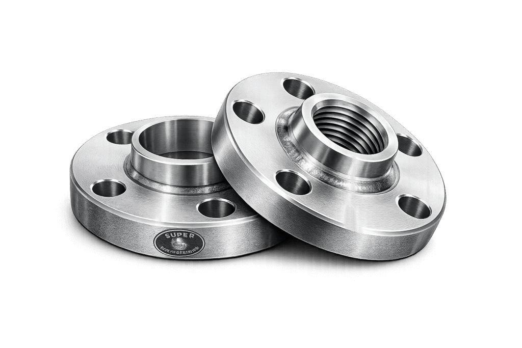
Role of Male Female Flanges in Pressure Piping Systems
Male Female Flanges are deployed in pressure-retaining bolted joints where alignment precision and controlled gasket compression are critical to system integrity. These flange configurations are specifically engineered to address leakage risks associated with misalignment, over-compression, and gasket displacement.
In high-consequence piping systems, the failure mode is typically not structural collapse of the flange but loss of sealing integrity at the gasket interface. Male Female Flanges mitigate this risk through mechanically guided face engagement.
Functional Role in System Design
Male Female Flanges serve the following functions:
- Provide positive alignment during assembly
- Ensure controlled gasket seating
- Prevent gasket extrusion under pressure
- Maintain consistent sealing stress across the flange face
- Reduce dependency on installer skill for alignment accuracy
Typical Applications
These flange configurations are used in:
Oil & Gas Upstream and Midstream
- Wellhead piping
- Flowlines
- High-pressure manifolds
Refineries
- Hydroprocessing units
- Crude distillation systems
- High-temperature transfer lines
Power Plants
- Boiler feedwater systems
- Steam lines (high pressure/high temperature)
- Turbine auxiliary piping
LNG Terminals
- Cryogenic service lines
- Loading/unloading arms
- Storage tank piping
Chemical Processing
- Corrosive fluid transfer systems
- High-purity process lines
Offshore Platforms
- Space-constrained piping systems
- Vibration-prone installations
Why Male Female Configuration is Selected
Compared to Raised Face (RF) and Flat Face (FF) flanges:
| Parameter | Male Female Flanges | Raised Face (RF) | Flat Face (FF) |
|---|---|---|---|
| Alignment | Positive mechanical alignment | Manual alignment | Manual alignment |
| Gasket Control | Controlled via recess | Limited | No control |
| Leakage Risk | Lower | Moderate | Higher |
| Gasket Containment | High | Moderate | Low |
| Suitability | Critical services | General service | Low-pressure systems |
Selection Justification:
Male Female Flanges are chosen when:
- Gasket compression must be controlled precisely
- Misalignment cannot be tolerated
- Pressure cycling is significant
- Leakage consequences are severe
2. Technical Definition
Male Female Flanges are defined as:
A precision-machined flange pair consisting of:
- One flange with a protruding male face
- One flange with a matching recessed female face
Designed to achieve controlled gasket compression and self-alignment during assembly
Face Geometry Configuration
- Male Face:
- Raised projection
- Typically 1.6 mm to 6.4 mm height depending on class
- Female Face:
- Recessed groove
- Depth designed to accommodate male face + gasket
Gasket Containment Principle
The gasket is:
- Located within the female recess
- Confined radially by the recess walls
- Compressed axially by bolt load
This results in:
- Reduced lateral gasket movement
- Uniform compression
- Improved sealing efficiency
Difference from RF and FF
| Feature | Male Female | Raised Face | Flat Face |
|---|---|---|---|
| Gasket Position | Inside recess | On raised face | Entire face |
| Compression Control | High | Moderate | Low |
| Alignment | Self-aligning | External | External |
| Surface Contact | Partial | Partial | Full |
Super Industries
Global Manufacturer of Heavy & Custom Engineered Fasteners & Flanges
3. Engineering & Sealing Principle
Face Engagement Mechanics
During assembly:
- Male face enters female recess
- Flanges achieve concentric alignment
- Gasket is confined within recess
- Bolting applies axial compressive load
Controlled Gasket Seating
The depth of the female recess determines:
- Maximum allowable compression
- Prevention of over-compression
- Uniform stress distribution
Bolt Preload Distribution
Bolt tightening results in:
- Axial compressive force
- Load transfer through flange faces
- Gasket compression within controlled limits
Sealing Reliability Under Pressure Cycling
Male Female Flanges maintain sealing integrity due to:
- Gasket confinement
- Reduced relaxation effects
- Uniform stress distribution
- Resistance to vibration-induced displacement
Leakage Prevention Mechanism
Leakage is prevented through:
- Controlled gasket stress
- Elimination of misalignment gaps
- Reduced gasket creep
- Stable contact surface
4. Pressure & Load Engineering
Pressure Class Range
- Class 150
- Class 300
- Class 600
- Class 900
- Class 1500
- Class 2500
Internal Pressure Containment
Internal pressure generates:
- Axial separation force
- Radial expansion stress
These are resisted by:
- Bolt preload
- Flange rigidity
- Gasket sealing stress
Axial and Radial Load Distribution
- Axial Loads: Managed through bolt tension
- Radial Loads: Controlled by flange stiffness and face engagement
Thermal Expansion Behavior
- Differential expansion handled via:
- Elastic deformation
- Gasket compressibility
- Male Female configuration reduces:
- Misalignment due to thermal growth
Fatigue and Cyclic Loading
Suitable for:
- Pressure cycling systems
- Thermal cycling environments
Due to:
- Stable gasket positioning
- Reduced stress concentration
Bolt Load vs Pressure Interaction
System equilibrium condition:
- Bolt preload ≥ internal pressure force + gasket seating stress
Dimensional & Design Logic
Critical Design Parameters
- Male face height
- Female recess depth
- Bolt circle diameter (BCD)
- Flange thickness
- Bore alignment
Geometric Control Requirements
Concentricity
- Ensures alignment between pipe bore and flange faces
Perpendicularity
- Face must be perpendicular to bore axis
Surface Finish Requirements
Typical Ra values:
- 3.2 µm to 6.3 µm (serrated finish)
- Ensures:
- Gasket grip
- Controlled sealing interface
Machining Precision
- CNC-controlled machining
- Tight tolerance adherence
- Face flatness control
5. Applicable Standards
Male Female Flanges are manufactured and validated in accordance with international pressure equipment and piping standards. Compliance ensures interchangeability, pressure integrity, and acceptance across EPC projects.
Primary Dimensional Standards
ASME B16.5
- Covers: NPS ½” to 24”
- Pressure Classes: 150 to 2500
- Defines:
- Flange dimensions
- Facing types (including Male Female)
- Tolerances
- Bolt patterns
ASME B16.47 (Series A & B)
- Covers: NPS 26” to 60”
- Used for:
- Large-diameter pipelines
- Offshore and transmission systems
Material Standards (ASTM)
| Category | Standard | Scope |
|---|---|---|
| Carbon Steel | ASTM A105 | Forged carbon steel for ambient/high temp |
| Low Temperature CS | ASTM A350 LF2 | Impact-tested for low temperature service |
| Stainless Steel | ASTM A182 | Alloy and stainless forged flanges |
| Alloy Steel | ASTM A182 F11/F22 | High temp and creep-resistant alloys |
European Standards
- EN 1092-1
- Metric flange system
- PN ratings (PN10 to PN100)
- DIN Standards
- DIN 2527 / DIN 2633 / DIN 2635 (depending on type/class)
Standard Mapping to Engineering Parameters
| Standard | Pressure Rating System | Temperature Basis | Application |
|---|---|---|---|
| ASME B16.5 | Class 150–2500 | Material-dependent | Oil & Gas, Power |
| ASME B16.47 | Class 75–900 | Material-dependent | Large pipelines |
| EN 1092-1 | PN system | Defined temp curves | EU projects |
Relevance to Male Female Flanges
- Face configurations (male/female) are standardized under ASME B16.5
- Dimensional tolerances ensure:
- Proper face engagement
- Gasket seating reliability
- Compliance ensures interchangeability across global projects
6. Material & Grade Options
Material selection for Male Female Flanges is driven by:
- Pressure rating
- Temperature range
- Corrosion environment
- Fluid characteristics
Carbon Steel
ASTM A105
- General-purpose forged carbon steel
- Suitable for:
- Ambient to moderately high temperatures
- Good machinability and strength
ASTM A350 LF2
- Low-temperature carbon steel
- Impact-tested
- Suitable for:
- Sub-zero service (down to -46°C or lower)
Stainless Steel
ASTM A182 F304
- Austenitic stainless steel
- Good corrosion resistance
- Suitable for:
- General chemical processing
ASTM A182 F316
- Molybdenum-bearing stainless steel
- Enhanced resistance to:
- Chlorides
- Marine environments
Alloy Steel
ASTM A182 F11 / F22
- Chromium-molybdenum alloys
- Designed for:
- High-temperature service
- Creep resistance
- Common in:
- Power plants
- Refineries
Duplex / Super Duplex Stainless Steel
- Dual-phase microstructure
- High strength + corrosion resistance
- Suitable for:
- Offshore platforms
- Seawater systems
- Aggressive chemical environments
Material Comparison Table
| Material Grade | Yield Strength (MPa) | Tensile Strength (MPa) | Temperature Range | Corrosion Resistance | Typical Application |
|---|---|---|---|---|---|
| ASTM A105 | ~250 | 485–620 | -29°C to 425°C | Moderate | Oil & gas piping |
| ASTM A350 LF2 | ~250 | 485–620 | Down to -46°C | Moderate | Cryogenic systems |
| ASTM A182 F304 | ~205 | 515–720 | Up to 870°C | Good | Chemical processing |
| ASTM A182 F316 | ~205 | 515–720 | Up to 870°C | High | Marine, offshore |
| ASTM A182 F11 | ~275 | 415–585 | Up to 540°C | Moderate | Power plants |
| ASTM A182 F22 | ~415 | 585–760 | Up to 600°C | Moderate | High-temp service |
| Duplex SS | ~450 | 620–880 | -50°C to 300°C | Very High | Offshore, seawater |
7. Heat Treatment Information
Heat treatment is applied to achieve:
- Required mechanical properties
- Microstructural stability
- Resistance to brittle fracture
Normalizing
- Applied to carbon steel
- Refines grain structure
- Improves:
- Strength
- Uniformity
Quenching & Tempering (Q&T)
- Used for alloy steels
- Process:
- Rapid cooling (quenching)
- Controlled reheating (tempering)
Effect:
- Increased strength
- Improved toughness
Solution Annealing
- Applied to stainless steels
- Dissolves carbides
- Restores corrosion resistance
Stress Relieving
- Removes residual stresses from:
- Forging
- Machining
Hardness Control
- Ensures compliance with:
- NACE requirements (if applicable)
- Prevents:
- Sulfide stress cracking
Impact Testing
- Required for low-temperature service
- Conducted as per:
- ASTM A370
- Ensures:
- Toughness at operating temperature
8. Manufacturing Process
Manufacturing of Male Female Flanges follows a controlled, traceable, multi-stage process.
1. Raw Material Inspection
- Verification of:
- Mill test certificates
- Chemical composition
- PMI (Positive Material Identification)
2. Forging
- Closed-die or open-die forging
- Produces:
- Refined grain flow
- Improved mechanical strength
3. Rough Machining
- Initial shaping of:
- Outer diameter
- Bore
- Thickness
4. CNC Machining of Faces
Critical stage for Male Female Flanges:
- Machining of:
- Male projection
- Female recess
- Controlled parameters:
- Depth
- Height
- Concentricity
5. Groove Precision Control
- Ensures:
- Proper gasket fit
- Controlled compression
6. Drilling
- Bolt holes drilled as per:
- BCD
- Tolerance limits
- Angular accuracy maintained
7. Heat Treatment
- Applied as per material specification
8. Surface Finishing
- Serrated or smooth finish
- Coating application (if required)
9. Final Inspection
- Dimensional verification
- NDT (if required)
- Surface quality check
10. Marking & Traceability
Includes:
- Heat number
- Material grade
- Pressure class
- Manufacturer identification
Surface Finish Options
Surface condition affects:
- Corrosion resistance
- Handling durability
- Sealing performance
Common Surface Treatments
Phosphate Coating
- Temporary corrosion protection
- Used for carbon steel
Zinc Plating
- Electroplated coating
- Moderate corrosion resistance
Hot-Dip Galvanizing
- Thick zinc coating
- Suitable for outdoor exposure
PTFE Coating
- Chemical resistance
- Low friction surface
Passivation (Stainless Steel)
- Removes free iron
- Enhances corrosion resistance
Black Oxide
- Minimal protection
- Used for indoor applications
Surface Roughness (Ra Values)
- Typical: 3.2 – 6.3 µm
- Achieved via:
- Phonographic serrations
- Function:
- Enhances gasket grip
- Prevents slippage
Impact on Sealing Performance
Surface finish directly influences:
- Gasket seating stress
- Leak tightness
- Long-term sealing stability
9. Dimensional Engineering Tables
Dimensional control in Male Female Flanges is governed by ASME B16.5 / B16.47 tolerances, with additional precision applied to face geometry (male height & female recess depth) to ensure controlled gasket compression.
A. Representative Dimension Table (ASME B16.5 – Male Female Flanges)
Values indicative for engineering reference. Project-specific drawings govern final supply.
| NPS (in) | Pressure Class | Flange OD (mm) | Bolt Circle (BCD mm) | Bolt Size | No. of Bolts | Male Face Height (mm) | Female Depth (mm) | Flange Thickness (mm) |
|---|---|---|---|---|---|---|---|---|
| 1” | 150 | 108 | 79 | M14 | 4 | 1.6 | 2.0 | 14.3 |
| 2” | 300 | 165 | 127 | M16 | 8 | 1.6 | 2.4 | 20.6 |
| 4” | 600 | 273 | 216 | M20 | 8 | 3.2 | 3.6 | 38.1 |
| 6” | 900 | 381 | 318 | M24 | 12 | 3.2 | 4.0 | 55.6 |
| 8” | 1500 | 483 | 406 | M30 | 12 | 6.4 | 6.8 | 79.4 |
| 10” | 2500 | 584 | 495 | M36 | 16 | 6.4 | 7.2 | 108.0 |
Dimensional Engineering Notes
- Female depth > Male height ensures:
- No metal-to-metal contact before gasket compression
- Face concentricity tolerance: typically ≤ 0.25 mm
- Perpendicularity tolerance: critical for uniform bolt load transfer
- Bolt hole positional tolerance: ensures stress symmetry
Pressure Rating Table
Pressure-temperature ratings are governed by material group and ASME classification.
B. Pressure Rating (Indicative – ASTM A105)
| Class | 38°C (bar) | 100°C (bar) | 200°C (bar) | 300°C (bar) | 400°C (bar) |
|---|---|---|---|---|---|
| 150 | 19.6 | 17.7 | 15.5 | 13.4 | 11.0 |
| 300 | 51.1 | 46.0 | 40.0 | 34.5 | 28.3 |
| 600 | 102.1 | 91.9 | 79.9 | 68.9 | 56.6 |
| 900 | 153.2 | 137.9 | 119.8 | 103.4 | 84.9 |
| 1500 | 255.3 | 229.8 | 199.6 | 172.4 | 141.5 |
| 2500 | 425.5 | 382.9 | 332.7 | 287.4 | 235.8 |
Engineering Interpretation
- Pressure rating decreases with temperature due to:
- Material strength reduction
- Male Female configuration does not change rating, but:
- Improves sealing reliability within rating limits
Torque Chart
Torque application is critical to achieve:
- Required gasket seating stress
- Leak-tight performance
- Bolt stress within allowable limits
C. Torque Values (Indicative – Carbon Steel Bolting, B7 / 2H)
| Bolt Size | Lubricated Torque (Nm) | Dry Torque (Nm) | Target Bolt Stress (% Yield) |
|---|---|---|---|
| M16 | 110 – 130 | 150 – 170 | 60–70% |
| M20 | 220 – 260 | 300 – 340 | 60–70% |
| M24 | 380 – 450 | 520 – 580 | 60–70% |
| M30 | 750 – 880 | 1000 – 1150 | 60–70% |
| M36 | 1300 – 1500 | 1700 – 1900 | 60–70% |
Torque Application Notes
- Lubrication reduces friction → improves preload accuracy
- Torque variation tolerance: typically ±10%
- Use calibrated torque wrench or hydraulic tensioners for critical joints
Preload Calculation Guide
Correct bolt preload is fundamental to sealing integrity.
D. Bolt Load Formula
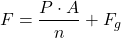
Where:
- F = Required bolt load per bolt
- P = Internal pressure
- A = Effective gasket area
- n = Number of bolts
- Fg = Gasket seating force
Bolt Stress Formula

Where:
- σ = Bolt stress
- F = Bolt force
- Ab = Bolt stress area
Sample Calculation
Given:
- Pressure (P) = 100 bar
- Gasket effective area (A) = 5000 mm²
- Number of bolts (n) = 8
- Gasket seating force (Fg) = 20 kN
Calculation:
- Pressure force = 100 × 5000 = 500,000 N
- Load per bolt = 500,000 / 8 = 62,500 N
- Total bolt load = 62,500 + 20,000 = 82,500 N per bolt
Safety Factor
- Typical design factor: 1.5 to 2.0
- Ensures:
- Compensation for relaxation
- Thermal effects
- Installation variability
Engineering Considerations
- Over-tightening → gasket crushing
- Under-tightening → leakage
- Male Female design helps limit over-compression
Mechanical Properties Table
E. Mechanical Properties
| Material | Yield Strength (MPa) | Tensile Strength (MPa) | Elongation (%) | Hardness (HB) |
|---|---|---|---|---|
| ASTM A105 | ≥250 | 485–620 | ≥22 | 137–187 |
| ASTM A350 LF2 | ≥250 | 485–620 | ≥22 | 137–187 |
| ASTM A182 F304 | ≥205 | 515–720 | ≥30 | ≤201 |
| ASTM A182 F316 | ≥205 | 515–720 | ≥30 | ≤217 |
| ASTM A182 F22 | ≥415 | 585–760 | ≥20 | 170–220 |
Engineering Relevance
- Higher yield strength → higher allowable bolt preload
- Elongation → ductility for flange deformation tolerance
- Hardness → resistance to wear and indentation
Corrosion Comparison Table
F. Corrosion Resistance Comparison
| Material | General Corrosion | Chloride Resistance | Sulfide Stress Resistance | Marine Suitability |
|---|---|---|---|---|
| A105 | Low | Poor | Moderate | Not suitable |
| LF2 | Low | Poor | Moderate | Not suitable |
| F304 | Moderate | Limited | Moderate | Limited |
| F316 | High | Good | Moderate | Suitable |
| Duplex SS | Very High | Excellent | High | Highly suitable |
Material Selection Insight
- Chloride environments → F316 or Duplex
- Sour service → controlled hardness + NACE compliance
- Offshore → Duplex preferred
10. Inspection & Quality Control
Inspection ensures compliance with:
- Design specifications
- Material standards
- Dimensional tolerances
Incoming Material Verification
- Mill Test Certificate (MTC) validation
- PMI (Positive Material Identification)
- Heat number traceability
Non-Destructive Testing (NDT)
Ultrasonic Testing (UT)
- Detects internal discontinuities
Magnetic Particle Inspection (MPI)
- Surface/subsurface crack detection (ferromagnetic materials)
Dye Penetrant Inspection (DPI)
- Surface crack detection (all materials)
Dimensional Inspection
Critical checks include:
- Male face height
- Female recess depth
- Flange thickness
- Bolt hole alignment
- BCD accuracy
Hardness Testing
- Ensures compliance with:
- Material specifications
- NACE limits (if applicable)
Hydrostatic Testing (If Applicable)
- Verifies:
- Pressure integrity
- Leak tightness of assembled joint (system-level)
Surface Finish Verification
- Roughness measurement (Ra value)
- Serration profile inspection
Certification
- EN 10204 3.1 – Manufacturer certification
- EN 10204 3.2 – Third-party inspection (if required)
Third-Party Inspection
Common agencies:
- TPI as per EPC requirement
- Witness and hold points include:
- Raw material inspection
- Final dimensional check
- NDT verification
Traceability System
Each flange is marked with:
- Heat number
- Material grade
- Size and pressure class
- Manufacturer identification
Quality Assurance Outcome
The inspection protocol ensures:
- Dimensional compliance
- Material authenticity
- Sealing reliability
- EPC acceptance readiness
11. Industries Served
Male Female Flanges are deployed in pressure-critical and leakage-sensitive piping systems where alignment accuracy and gasket control are required to meet design integrity and operational reliability criteria.
Oil & Gas (Upstream / Midstream / Downstream)
Applications include:
- Wellhead and Christmas tree piping
- High-pressure flowlines and manifolds
- Refinery process units (hydrocracking, reforming)
Engineering Requirement:
- Resistance to pressure cycling
- Controlled sealing under fluctuating loads
- Compatibility with hydrocarbon service
Petrochemical & Chemical Processing
Applications include:
- Corrosive fluid transfer systems
- Reactor inlet/outlet piping
- Solvent and acid handling lines
Engineering Requirement:
- Material compatibility (F316, Duplex)
- Leak prevention in hazardous media
- Controlled gasket confinement
Power Generation (Thermal / Nuclear / Combined Cycle)
Applications include:
- Boiler feedwater systems
- Main steam lines
- Turbine auxiliary piping
Engineering Requirement:
- High-temperature strength (F11 / F22)
- Resistance to creep and fatigue
- Stability under thermal expansion
LNG & Cryogenic Systems
Applications include:
- LNG storage and transfer pipelines
- Cryogenic process lines
- Vapor return systems
Engineering Requirement:
- Low-temperature toughness (LF2, Stainless Steel)
- Impact resistance at sub-zero temperatures
- Gasket integrity under thermal contraction
Offshore & Marine Installations
Applications include:
- Platform piping systems
- Subsea modules
- Seawater cooling systems
Engineering Requirement:
- Resistance to chloride-induced corrosion
- Vibration tolerance
- Compact alignment-friendly design
General Industrial & Process Plants
Applications include:
- High-pressure utility lines
- Chemical dosing systems
- Specialized process piping
Engineering Requirement:
- Standard compliance
- Maintainability
- Interchangeability
12. Export Capability
Super Industries operates as a manufacturer and global exporter of Male Female Flanges, aligned with EPC procurement frameworks and international compliance requirements.
Export Regions
- United States (ASME-based projects)
- European Union (EN / PED compliance)
- Middle East (Oil & Gas EPC projects)
- Southeast Asia & Far East
- Africa (Energy and infrastructure projects)
Packaging Standards
- Wooden crates (ISPM 15 compliant)
- Moisture barrier wrapping
- Anti-corrosion protection (VCI / oil coating)
- Individual flange protection for facing surfaces
Objective:
- Prevent mechanical damage
- Preserve machined face integrity
- Avoid corrosion during transit
Documentation Package
Supplied documentation typically includes:
- Mill Test Certificates (EN 10204 3.1 / 3.2)
- Dimensional inspection reports
- NDT reports (UT / MPI / DPI)
- Heat treatment records
- PMI reports
- Compliance declarations (ASME / EN)
Logistics Capability
- Containerized shipments (FCL / LCL)
- Project-based dispatch planning
- Marking aligned with EPC tagging systems
- Batch traceability through shipment
13. Procurement & Installation Engineering View
Alignment Requirements
Male Female Flanges reduce dependency on external alignment, but proper installation still requires:
- Clean flange faces
- Verification of concentricity
- Absence of foreign particles
Gasket Positioning
- Gasket must be placed within female recess
- Ensure:
- Correct size
- Proper seating
- No folding or damage
Bolt Tightening Procedure
Cross-Pattern Tightening
Sequence:
- Initial snug tightening
- 30% torque (cross pattern)
- 60% torque (cross pattern)
- 100% torque (final pass)
Torque Application Control
- Use calibrated torque wrench or hydraulic tensioner
- Apply uniform torque across all bolts
- Avoid sequential tightening
Re-Torque Practices
- Re-torque after:
- Initial pressurization
- Thermal stabilization (if applicable)
Inspection Checkpoints During Installation
- Face cleanliness
- Gasket alignment
- Bolt lubrication condition
- Torque verification
- Gap uniformity check
Common Installation Risks
| Issue | Cause | Impact |
|---|---|---|
| Misalignment | Improper assembly | Uneven gasket stress |
| Over-tightening | Excess torque | Gasket crushing |
| Under-tightening | Insufficient preload | Leakage |
| Contamination | Dirty faces | Seal failure |
Custom Engineering Capabilities
Super Industries provides project-specific manufacturing of Male Female Flanges aligned with EPC specifications and design deviations.
Custom Design Options
- Non-standard male face heights
- Modified female recess depths
- Special gasket seating configurations
- Custom bore sizes
Non-Standard Drilling
- Project-specific bolt hole patterns
- Compatibility with legacy systems
Heavy Thickness & High-Pressure Designs
- Increased flange thickness for:
- High-pressure service
- Fatigue resistance
Material Customization
- Duplex / Super Duplex
- High alloy materials
- NACE-compliant materials
Marking & Traceability
- Project-specific tagging
- QR / barcode traceability (if required)
- Heat-wise traceability maintained
Engineering Summary & System-Level Conclusion
Male Female Flanges represent a precision-engineered flange facing configuration developed to address limitations in conventional flange designs related to:
- Gasket misalignment
- Uncontrolled compression
- Leakage under cyclic loading
Engineering Advantages
- Controlled gasket compression via recess geometry
- Self-alignment during assembly
- Improved sealing reliability under pressure and temperature variations
- Reduced risk of gasket extrusion and displacement
Design Suitability
Recommended for:
- High-pressure systems
- Critical sealing applications
- Cyclic loading environments
- Hazardous fluid service
Standards Compliance
Manufactured in accordance with:
- ASME B16.5 / B16.47
- ASTM material standards
- EN / DIN equivalents (as required)
EPC Evaluation Outcome
From an EPC and consultant evaluation perspective:
- Face geometry demonstrates understanding of sealing mechanics
- Manufacturing controls indicate dimensional discipline
- Inspection protocols ensure traceability and compliance
- Material selection reflects application-specific engineering judgment
Final Engineering Position
Male Female Flanges are not a general-purpose solution but a targeted engineering configuration applied where:
- Sealing reliability is critical
- Alignment tolerance is minimal
- Operational consequences of leakage are high
Their use reflects a design-driven selection approach, aligned with pressure system integrity requirements and international piping standards.