
ASME B16.5 FORGED FLANGES
Super Industries
“Global Manufacturer of Heavy & Custom Engineered Fasteners for Oil & Gas, Power & EPC Contractors.”
1. Industry Context & System Relevance
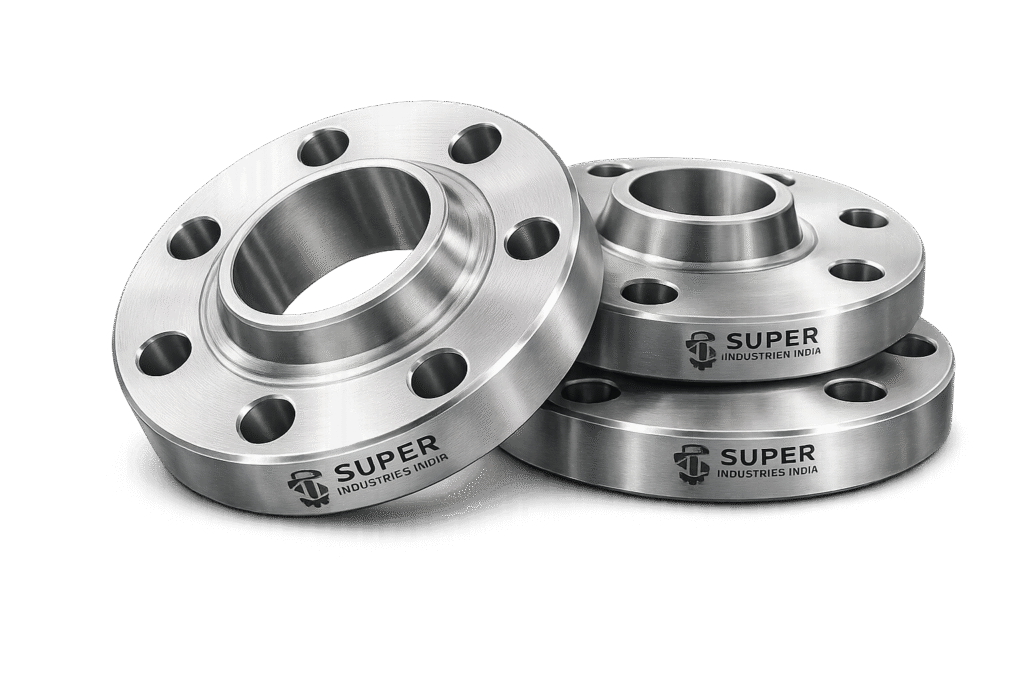
Role of ASME B16.5 Forged Flanges in Pressure Piping Systems
ASME B16.5 forged flanges are standardized forged mechanical connectors designed for joining piping components, valves, pumps, pressure vessels, heat exchangers, and process equipment within pressure-containing systems. These flanges establish detachable bolted joints that permit inspection, maintenance, cleaning, equipment replacement, hydrotesting, and system expansion without permanent cutting or rewelding of piping systems.
In refinery, petrochemical, LNG, offshore, and thermal power facilities, flange joints represent critical pressure-retaining interfaces where mechanical integrity, gasket sealing reliability, and bolt load stability directly affect plant safety, environmental containment, and operational continuity.
Forged flanges are widely applied in:
- High-pressure hydrocarbon process piping
- Steam distribution systems
- Cryogenic LNG transfer lines
- Offshore process modules
- Pressure vessel nozzle interfaces
- Utility water systems
- Chemical process piping
- Boiler feedwater systems
- Compressor and turbine piping
- Hydrogen and sour service applications
The engineering function of a forged flange assembly extends beyond simple mechanical connection. The flange system must maintain sealing integrity under combined operating conditions including:
- Internal pressure
- Thermal expansion
- Cyclic loading
- External piping loads
- Vibration
- Pressure pulsation
- Differential thermal growth
- Startup and shutdown transients
Pressure-Retaining Mechanical Joint Function
Unlike permanent welded joints, forged flange assemblies are detachable mechanical joints designed to:
- Transfer pressure loads safely
- Compress gaskets uniformly
- Maintain controlled bolt preload
- Resist flange rotation
- Prevent leakage under thermal cycling
- Permit disassembly during shutdown maintenance
A complete bolted flange joint typically consists of:
- Two mating forged flanges
- Gasket element
- Stud bolts and nuts
- Controlled tightening system
The flange assembly converts bolt preload into gasket compression. Proper gasket compression generates sufficient sealing stress to resist internal process pressure and prevent media leakage during operating conditions.
Importance in Refinery and Petrochemical Systems
Refineries and petrochemical plants contain thousands of flange joints operating under varying combinations of:
- High temperature
- Corrosive process fluids
- Cyclic thermal loading
- High pressure
- Hydrogen exposure
- Vibration
- Vacuum conditions
In such environments, ASME forged flanges provide several engineering advantages:
Maintainability
Bolted flange systems allow rapid equipment isolation and maintenance access during plant shutdowns. Exchangers, pumps, valves, strainers, and instrumentation can be disconnected without cutting piping systems.
Inspection Accessibility
Critical process systems require periodic inspection under statutory and plant integrity programs. Flanged joints enable:
- Internal visual inspection
- Gasket replacement
- NDE access
- Pressure testing
- Corrosion monitoring
System Expansion Flexibility
Large industrial facilities undergo phased modifications and revamps. Flanged systems simplify:
- Tie-ins
- Equipment replacement
- Capacity expansion
- Temporary isolation
- Modular construction
LNG & Cryogenic Service Applications
LNG facilities impose severe thermal contraction conditions due to cryogenic operating temperatures approaching −196°C. Under such conditions, forged flanges must maintain:
- Toughness at low temperature
- Bolt preload stability
- Gasket seating integrity
- Resistance to brittle fracture
Forged flange materials such as ASTM A350 LF2 and stainless steel grades are commonly selected because forging improves structural uniformity and minimizes internal discontinuities that could become fracture initiation sites under cryogenic stress conditions.
Cryogenic applications include:
- LNG storage terminals
- Liquefaction plants
- Regasification facilities
- Cryogenic process skids
- Low-temperature transfer piping
Offshore & FPSO System Relevance
Offshore platforms and FPSO systems expose flange assemblies to:
- Cyclic wave-induced vibration
- Salt-laden atmosphere
- Chloride corrosion
- Mechanical fatigue
- Dynamic loading
- Restricted maintenance access
Forged flanges are preferred because the forging process produces:
- Improved grain continuity
- Enhanced fatigue resistance
- Better mechanical integrity
- Reduced porosity risk
- Higher structural reliability
In offshore systems, forged weld neck flanges are particularly favored for critical service due to their superior stress distribution characteristics.
Power Generation Systems
Thermal and combined-cycle power plants operate piping systems under elevated temperature and pressure conditions involving:
- Superheated steam
- Cyclic startup/shutdown operation
- Creep exposure
- Thermal fatigue
- High-pressure feedwater
Alloy steel forged flanges such as ASTM A182 F11, F22, and F91 are commonly applied in:
- Main steam systems
- Reheat piping
- Boiler systems
- Turbine bypass lines
- High-energy piping systems
The forged construction enhances creep strength reliability and long-term structural performance under sustained thermal loading.
Pressure Vessel Nozzle Connections
Pressure vessels, reactors, columns, and heat exchangers frequently incorporate flanged nozzle connections to permit:
- Equipment isolation
- Piping attachment
- Maintenance accessibility
- Internal inspection
- Instrumentation installation
Forged weld neck flanges are widely utilized at pressure vessel nozzle interfaces because tapered hub geometry reduces local stress concentration between:
- Vessel nozzle neck
- Weld transition
- Flange hub
- Connected piping
This stress reduction improves fatigue life under pressure cycling and thermal expansion conditions.
Super Industries
Global Manufacturer of Heavy & Custom Engineered Fasteners & Flanges
Why Forged Flanges Are Preferred in Critical Pressure Systems
Forged vs Fabricated Flanges
Forged flanges differ fundamentally from fabricated flanges in manufacturing methodology and structural integrity.
Forged Flanges
Produced through controlled plastic deformation of heated billets or forged rings.
Characteristics include:
- Refined grain structure
- Improved directional grain flow
- Reduced internal discontinuities
- Enhanced toughness
- Higher fatigue resistance
- Better pressure containment reliability
Fabricated Flanges
Produced through cutting, rolling, and welding of plate material.
Potential limitations include:
- Weld discontinuities
- Non-uniform grain orientation
- Reduced fatigue resistance
- Heat affected zones
- Greater inspection complexity
For critical pressure systems involving cyclic loading, high pressure, or elevated temperature, forged flanges are generally preferred due to superior metallurgical integrity.
Grain Flow Orientation Benefits
During forging operations, metal grain flow follows the contour of the component geometry. This directional grain orientation improves:
- Impact resistance
- Fatigue strength
- Crack propagation resistance
- Structural continuity
- Pressure containment capability
The continuous grain structure produced during forging enhances resistance to cyclic stress and fluctuating pressure conditions commonly encountered in industrial piping systems.
Cyclic Loading & Fatigue Resistance
Industrial piping systems rarely operate under steady-state conditions. Pressure and temperature fluctuations generate cyclic stresses that can initiate fatigue cracking over time.
Forged flanges improve resistance to:
- Thermal fatigue
- Pressure cycling fatigue
- Vibration-induced cracking
- Mechanical load fluctuation
- Startup/shutdown stress cycling
This is particularly important in:
- Offshore systems
- Compressor discharge lines
- Steam systems
- Reciprocating equipment piping
- High-vibration process lines
2. Technical Definition
ASME B16.5 forged flanges are forged pressure-retaining piping connectors manufactured in accordance with ASME B16.5 dimensional and pressure-temperature rating requirements for NPS 1/2” through 24”.
These components are designed to create bolted gasketed joints within piping systems and associated pressure equipment.
The ASME B16.5 standard governs:
- Dimensions
- Facing configurations
- Pressure classes
- Tolerances
- Marking requirements
- Material compatibility
- Bolt hole arrangement
- Gasket seating geometry
Forging-Based Manufacturing Philosophy
The manufacturing philosophy behind forged flanges emphasizes:
- Mechanical integrity
- Grain refinement
- Controlled deformation
- Dimensional repeatability
- Pressure boundary reliability
Forged flanges are typically manufactured from:
- Forged billets
- Rolled forged rings
- Open die forgings
The forging process enhances material soundness while improving resistance to:
- Porosity
- Lamination
- Shrinkage discontinuities
- Segregation defects
Pressure-Temperature Rating System
ASME B16.5 establishes standardized pressure-temperature ratings for flange materials based on:
- Material allowable stress
- Operating temperature
- Material group classification
- Pressure class designation
Common pressure classes include:
- Class 150
- Class 300
- Class 600
- Class 900
- Class 1500
- Class 2500
The allowable pressure decreases as operating temperature increases because material strength reduces at elevated temperature.
Flange Types
Weld Neck Forged Flange (WN)
Weld neck forged flanges incorporate a tapered hub transitioning gradually into the pipe wall through a butt-weld connection.
Engineering Characteristics
- Long tapered hub
- Full penetration butt weld
- Bore matching to pipe ID
- Reduced stress concentration
- Improved fatigue resistance
Applications
- High-pressure service
- Elevated temperature systems
- Severe cyclic conditions
- Offshore piping
- Critical process lines
The tapered hub distributes stresses more uniformly between pipe and flange, minimizing abrupt geometric transitions.
Slip-On Forged Flange (SO)
Slip-on forged flanges are designed for pipe insertion through the flange bore followed by dual fillet welding.
Characteristics
- Simplified alignment
- Lower installation cost
- Dual fillet weld construction
- Larger bore than pipe OD
Typical Applications
- Utility piping
- Low-pressure systems
- Cooling water lines
- Non-critical services
Slip-on flanges are generally less suitable for severe cyclic or high-pressure conditions due to reduced fatigue performance compared with weld neck flanges.
Blind Forged Flange (BL)
Blind forged flanges function as pressure-retaining end closures for piping systems and equipment nozzles.
Functions
- Pipeline isolation
- Future expansion provision
- Inspection access
- Hydrotest closure
Because blind flanges experience significant hydrostatic end force loading, flange thickness increases substantially at higher pressure classes.
Socket Weld Forged Flange (SW)
Socket weld forged flanges incorporate a recessed socket for pipe insertion followed by fillet seal welding.
Characteristics
- Small-bore service suitability
- High-pressure capability
- Improved alignment
- Reduced leakage risk
Common Applications
- Instrument piping
- High-pressure utility systems
- Steam tracing
- Hydraulic systems
Socket weld configurations are generally used in smaller nominal pipe sizes.
Threaded Forged Flange (TH)
Threaded forged flanges contain internal tapered threads allowing pipe connection without welding.
Engineering Advantages
- No hot work required
- Suitable for hazardous environments
- Simplified field installation
- Useful in low-temperature service
Limitations
- Restricted pressure-temperature applicability
- Thread stress concentration
- Limited fatigue resistance
Threaded flanges are commonly used where welding must be avoided.
Lap Joint Forged Flange (LJ)
Lap joint forged flanges operate with stub ends and permit rotational alignment of bolt holes.
Engineering Benefits
- Rotational freedom
- Simplified assembly
- Reduced alignment difficulty
- Cost reduction in exotic alloy systems
These flanges are frequently used in:
- Corrosion-resistant piping
- Stainless steel systems
- Lined piping
- Systems requiring frequent dismantling
Facing Types
Raised Face (RF)
Raised face flanges incorporate a concentric raised gasket seating surface.
Functions
- Concentrates gasket load
- Improves sealing stress
- Supports spiral wound gaskets
- Enhances pressure containment
RF flanges are the most widely used facing configuration in refinery and petrochemical systems.
Flat Face (FF)
Flat face flanges contain a full-face sealing surface without a raised gasket area.
Applications
- Cast iron equipment
- Low-pressure utility systems
- Non-metallic flanges
Flat face designs reduce bending stress that could damage brittle mating equipment.
Ring Type Joint (RTJ)
RTJ flanges contain precision-machined grooves for metal ring gasket seating.
Engineering Principles
- Metal-to-metal sealing
- High contact stress concentration
- Controlled plastic deformation of ring gasket
- High-pressure sealing capability
RTJ systems are commonly used in:
- High-pressure hydrocarbon service
- Offshore systems
- High-temperature process units
- Critical refinery applications
The groove geometry must maintain strict dimensional accuracy to ensure sealing integrity.
Gasket Seating & Surface Finish Engineering
Proper flange sealing depends heavily on controlled surface finish and gasket interaction.
Spiral Serration Logic
Raised face flanges commonly incorporate phonographic or concentric serrations that:
- Improve gasket grip
- Prevent gasket extrusion
- Increase sealing efficiency
- Control gasket compression behavior
Surface finish roughness must remain within specified ranges to balance:
- Gasket bite
- Sealability
- Surface damage prevention
3. Engineering & Stress Principles
Internal Pressure Loading
Internal pressure generates multiple simultaneous stresses within a flange assembly:
- Hydrostatic end force
- Radial stress
- Circumferential stress
- Bolt tensile load
- Flange bending moment
The bolted flange joint must resist separation forces while maintaining sufficient gasket compression.
Hydrostatic End Force Generation
Internal pressure acting on pipe cross-sectional area produces axial separation force attempting to separate the flange joint.
The magnitude of this force increases proportionally with:
- Internal pressure
- Effective gasket diameter
- Pipe bore size
Bolt preload must exceed this separating force to maintain gasket sealing stress.
Bolt Preload Mechanics
Bolts function as elastic springs storing preload energy after tightening.
Controlled bolt preload is essential because it:
- Compresses the gasket
- Maintains joint integrity
- Prevents leakage
- Resists pressure-induced separation
Insufficient preload can cause:
- Gasket unloading
- Leakage initiation
- Flange rotation
- Joint instability
Excessive preload may cause:
- Gasket crushing
- Bolt yielding
- Flange distortion
Gasket Compression Theory
Gaskets require minimum compressive stress to establish an effective seal.
Two loading conditions govern flange gasket design:
Seating Condition
Initial gasket compression required during assembly.
Operating Condition
Residual gasket stress required during system pressurization and thermal operation.
Loss of gasket stress may occur due to:
- Bolt relaxation
- Thermal cycling
- Gasket creep
- Flange rotation
- Differential thermal expansion
Stress Components in Forged Flanges
Hoop Stress
Circumferential stress generated by internal pressure acting within piping walls and flange bore regions.
Longitudinal Stress
Axial stress produced by pressure end force and external piping loads.
Radial Stress
Stress acting radially through flange thickness due to bolt load and gasket reaction forces.
Hub Stress Concentration
The hub-to-flange transition experiences localized stress intensification due to geometry changes and bending moments.
Weld neck flange hubs reduce this concentration through gradual taper transition.
Bolt Tensile Loading
Bolts experience tensile loading resulting from:
- Initial tightening
- Internal pressure
- Thermal expansion effects
- External piping loads
Bolt stress stability is critical for long-term sealing reliability.
Gasket Seating Stress
The gasket must maintain sufficient compressive stress throughout operating conditions to prevent leakage paths.
Loss of gasket seating stress is a primary cause of flange leakage failures.
Why Weld Neck Forged Flanges Improve Reliability
Improved Stress Distribution
The tapered hub geometry distributes stresses gradually between pipe and flange.
This minimizes:
- Local stress concentration
- Abrupt section transition
- Fatigue crack initiation
Thermal Cycling Resistance
Repeated heating and cooling cycles generate expansion and contraction stresses.
Weld neck forged flanges improve thermal fatigue performance because:
- Tapered hubs reduce stiffness discontinuities
- Butt-weld transitions improve load transfer
- Bore alignment minimizes bending stress
Vibration Resistance
Rotating equipment and pulsating flow create vibration-induced fatigue loading.
Forged weld neck flanges provide superior resistance due to:
- Structural rigidity
- Improved load distribution
- Reduced stress concentration
- Better weld geometry
Flange Rotation Behavior
Under bolt preload and internal pressure, flanges tend to rotate outward around the gasket region.
Excessive flange rotation may cause:
- Gasket unloading
- Outer edge leakage
- Bolt load redistribution
- Seal instability
Flange rigidity and hub reinforcement are critical for minimizing rotational deformation.
Neutral Axis Transition
The tapered hub geometry shifts stress transition gradually between pipe and flange.
This improves:
- Bending load transfer
- Fatigue resistance
- Thermal expansion accommodation
- Structural continuity
External Piping Loads
Flange assemblies are frequently subjected to external loads including:
- Pipe weight
- Thermal expansion
- Wind loading
- Seismic loads
- Equipment nozzle loads
- Dynamic vibration
Combined loading conditions significantly affect flange sealing performance and must be considered during piping stress analysis.
Leakage Initiation Mechanisms
Leakage may originate from:
- Insufficient bolt preload
- Gasket creep relaxation
- Thermal cycling
- Flange distortion
- Surface finish damage
- Misalignment
- Excessive external loads
Proper flange design, gasket selection, bolt tightening, and alignment control are essential to maintain pressure boundary integrity.
4. Applicable Standards & Codes
ASME B16.5 forged flanges are governed by an interconnected framework of dimensional standards, pressure piping codes, metallurgical specifications, inspection requirements, and pressure equipment design rules. In EPC projects, flange compliance is not evaluated solely by dimensional conformity. Consultant review and third-party inspection generally assess:
- Pressure-temperature rating validity
- Material traceability
- Manufacturing route compliance
- Mechanical property verification
- NDE acceptance
- Heat treatment control
- Marking compliance
- Documentation traceability
For this reason, forged flange manufacturing must align simultaneously with ASME dimensional standards, ASTM material specifications, and applicable piping code requirements.
ASME Standards
ASME B16.5
ASME B16.5 is the primary dimensional and rating standard governing forged flanges and flanged fittings for:
- NPS 1/2” through 24”
- Pressure Classes 150 through 2500
The standard establishes requirements for:
- Dimensions
- Facing configurations
- Bolt hole arrangements
- Tolerances
- Pressure-temperature ratings
- Materials grouping
- Marking
- Testing references
The purpose of ASME B16.5 standardization is dimensional interchangeability across manufacturers and global supply chains.
Key engineering elements controlled under ASME B16.5 include:
- Bolt Circle Diameter (BCD)
- Facing dimensions
- Raised face height
- RTJ groove geometry
- Flange thickness
- Hub dimensions
- Bore sizing
- Drilling symmetry
The standard ensures that flanges manufactured by different qualified suppliers remain mechanically compatible within pressure piping systems.
ASME B16.47 Series A & Series B
ASME B16.47 governs large-diameter steel flanges from NPS 26” through 60”.
The standard is divided into:
Series A
Derived from MSS SP-44 dimensional philosophy.
Characteristics include:
- Larger flange thickness
- Fewer but larger bolts
- Higher rigidity
- Improved pressure retention
Commonly used in:
- Pipeline systems
- Offshore applications
- High-pressure transmission systems
Series B
Derived from former API 605 dimensions.
Characteristics include:
- Smaller bolt circle
- Lower flange weight
- Greater bolt quantity
- Reduced material consumption
Commonly used where space and weight optimization are required.
ASME B31.3 — Process Piping
ASME B31.3 governs process piping systems commonly used in:
- Refineries
- Petrochemical plants
- Chemical facilities
- LNG terminals
The code addresses:
- Pressure design
- Material selection
- Stress analysis
- Flexibility
- Fabrication
- Examination
- Testing
Forged flange selection under ASME B31.3 must consider:
- Design pressure
- Design temperature
- Fluid category
- Corrosion allowance
- Cyclic service
- Severe service applicability
ASME B31.1 — Power Piping
ASME B31.1 governs piping systems associated with:
- Thermal power plants
- Boiler systems
- High-energy steam lines
- Turbine systems
The code places significant emphasis on:
- Elevated temperature performance
- Creep resistance
- Thermal fatigue
- Sustained load analysis
Forged alloy steel flanges such as F11, F22, and F91 are commonly applied under B31.1 systems.
ASME Section VIII Division 1
ASME Section VIII Division 1 governs pressure vessel design and construction.
Forged flanges are frequently used for:
- Vessel nozzles
- Manways
- Closures
- Heat exchanger connections
- Pressure-retaining attachments
Flange selection in pressure vessels must consider:
- Vessel design pressure
- Corrosion allowance
- External nozzle loads
- Hydrotest conditions
- Thermal expansion
- Fatigue exposure
ASME Section II
ASME Section II provides allowable material stresses and material specification references used for pressure equipment design.
This section establishes:
- Temperature-dependent allowable stresses
- Material property databases
- Metallurgical requirements
- Mechanical property acceptance criteria
Pressure-temperature ratings in ASME B16.5 are fundamentally linked to allowable stress data from ASME Section II.
ASTM Material Standards
Carbon Steel Forged Flanges
ASTM A105
ASTM A105 is the most widely used forged carbon steel material specification for ASME forged flanges.
Engineering Characteristics
- Good mechanical strength
- Excellent machinability
- Good weldability
- Cost-effective fabrication
- Moderate temperature capability
Typical Applications
- Refinery piping
- Utility systems
- Hydrocarbon processing
- Water service
- Steam systems
ASTM A105 is generally suitable for moderate temperature service where low-temperature impact toughness is not critical.
Metallurgical Characteristics
ASTM A105 forged flanges typically contain:
- Ferrite-pearlite microstructure
- Moderate hardness
- Good ductility
- Balanced strength and toughness
The forging process improves material uniformity and reduces discontinuity risks compared with fabricated plate-based components.
ASTM A350 LF2
ASTM A350 LF2 is a low-temperature carbon steel forging grade designed for applications requiring improved notch toughness.
Engineering Significance
LF2 flanges are widely applied in:
- LNG systems
- Cryogenic piping
- Low-temperature hydrocarbon service
- Refrigerated process systems
Charpy Impact Requirements
A350 LF2 material typically requires impact testing to verify toughness at specified low temperatures.
Impact testing evaluates:
- Energy absorption capability
- Resistance to brittle fracture
- Crack propagation resistance
This becomes critical in cryogenic systems where carbon steels may otherwise become brittle.
Cryogenic Suitability
LF2 material maintains improved toughness characteristics at subzero temperatures due to:
- Controlled chemistry
- Heat treatment
- Refined grain structure
Forged LF2 flanges are commonly used in:
- LNG storage terminals
- Ethylene systems
- Refrigeration plants
- Low-temperature process piping
Stainless Steel Forged Flanges
ASTM A182 F304 / F304L
ASTM A182 F304 and F304L are austenitic stainless steel forging grades widely used for corrosion-resistant flange applications.
Engineering Characteristics
- Excellent general corrosion resistance
- Austenitic microstructure
- Good toughness
- Good weldability
- Hygienic surface compatibility
Applications
- Food processing systems
- Pharmaceutical piping
- Water treatment plants
- Chemical systems
- General corrosive service
Austenitic Structure
The austenitic crystal structure provides:
- Excellent toughness
- Non-magnetic characteristics
- Good ductility
- Resistance to brittle fracture
The low-carbon “L” grade minimizes sensitization risk during welding.
ASTM A182 F316 / F316L
F316 and F316L stainless steel forged flanges contain molybdenum additions improving resistance to chloride-related corrosion.
Engineering Advantages
- Improved pitting resistance
- Better crevice corrosion resistance
- Enhanced marine compatibility
- Superior chloride tolerance
Applications
- Offshore systems
- Marine piping
- Chemical processing
- Desalination plants
- Chloride-bearing environments
Chloride Resistance
Chloride environments can cause localized corrosion in stainless steels.
The molybdenum content in F316/F316L improves resistance to:
- Pitting
- Crevice attack
- Localized breakdown of passive film
This makes F316 preferred over F304 in marine and coastal applications.
Alloy Steel Forged Flanges
ASTM A182 F11
F11 alloy steel forged flanges are chromium-molybdenum alloy steels designed for elevated temperature applications.
Characteristics
- Improved creep resistance
- Better elevated temperature strength
- Good oxidation resistance
Applications
- Boiler systems
- Steam piping
- Refinery heater lines
- High-temperature hydrocarbon service
ASTM A182 F22
F22 alloy steel provides enhanced high-temperature mechanical performance compared with F11.
Engineering Benefits
- Improved creep strength
- Better hydrogen resistance
- Elevated temperature stability
Widely used in:
- Hydrogen service
- Hydroprocessing units
- Power generation systems
ASTM A182 F91
F91 is a high-performance chromium-molybdenum alloy steel used in ultra-high-temperature power applications.
Characteristics
- Exceptional creep resistance
- High elevated-temperature strength
- Advanced tempered martensitic structure
Applications
- Supercritical steam systems
- Combined cycle power plants
- High-energy piping
- Advanced thermal systems
F91 requires tightly controlled heat treatment due to its sensitive metallurgical structure.
Duplex Stainless Steel Forged Flanges
F51 Duplex Stainless Steel
F51 duplex stainless steel combines:
- Austenitic phase
- Ferritic phase
This dual-phase structure improves both strength and corrosion resistance.
Engineering Advantages
- Higher yield strength
- Better chloride resistance
- Improved stress corrosion cracking resistance
F53 Super Duplex Stainless Steel
F53 provides enhanced pitting resistance and higher corrosion resistance compared with standard duplex grades.
Applications
- Offshore seawater systems
- Subsea piping
- Marine injection systems
- Aggressive chloride environments
F55 Super Duplex Stainless Steel
F55 offers very high pitting resistance equivalent numbers (PREN) suitable for severe offshore environments.
Applications include:
- FPSO topside systems
- Desalination plants
- Seawater lift systems
- Offshore firewater systems
Duplex Metallurgical Engineering
Duplex stainless steels provide:
- High yield strength
- Reduced wall thickness potential
- Improved chloride resistance
- Better stress corrosion cracking resistance
Proper heat treatment is critical to maintain correct phase balance between ferrite and austenite.
Material Selection Engineering Logic
Forged flange material selection depends upon multiple operating parameters.
Pressure Service
Higher pressure systems generally require:
- Greater yield strength
- Higher bolt load resistance
- Improved fatigue performance
Corrosion Exposure
Material selection must account for:
- Chloride content
- Acid exposure
- Sulfur compounds
- Wet H2S conditions
- Oxygen concentration
Sour Service
Sour service environments containing hydrogen sulfide require:
- Hardness control
- Sulfide stress cracking resistance
- NACE compliance
Improper hardness or heat treatment may increase cracking susceptibility.
Cryogenic Service
Low-temperature systems require:
- Charpy impact toughness
- Fracture resistance
- Ductility retention
Materials such as LF2 and austenitic stainless steels are commonly selected.
High-Temperature Service
Elevated temperature applications require:
- Creep resistance
- Oxidation resistance
- Thermal fatigue resistance
Alloy steel grades such as F11, F22, and F91 are commonly used.
MATERIAL COMPARISON TABLE
| Material Grade | Minimum Yield Strength | Minimum Tensile Strength | Typical Hardness | Approximate Service Temperature Range | Corrosion Resistance | Typical Applications |
|---|---|---|---|---|---|---|
| ASTM A105 | 250 MPa | 485 MPa | Moderate | -29°C to 425°C | Moderate | Refinery & utility piping |
| ASTM A350 LF2 | 250 MPa | 485 MPa | Moderate | -46°C to 345°C | Moderate | Cryogenic & LNG service |
| ASTM A182 F304/F304L | 205 MPa | 515 MPa | Lower | -196°C to 540°C | Good | Chemical & hygienic systems |
| ASTM A182 F316/F316L | 205 MPa | 515 MPa | Lower | -196°C to 540°C | Very Good | Marine & chloride service |
| ASTM A182 F11 | 205 MPa | 415 MPa | Moderate | Up to 540°C | Moderate | Steam & heater piping |
| ASTM A182 F22 | 205 MPa | 415 MPa | Moderate | Up to 590°C | Moderate | Hydrogen & power systems |
| ASTM A182 F91 | 415 MPa | 585 MPa | Higher | Up to 650°C | Moderate | Supercritical steam systems |
| Duplex F51 | 450 MPa | 620 MPa | Moderate | -50°C to 300°C | Excellent | Offshore piping |
| Super Duplex F53/F55 | 550 MPa | 750 MPa | Moderate | -50°C to 315°C | Exceptional | Seawater & subsea systems |
5. Heat Treatment Engineering
Heat treatment significantly affects the mechanical integrity, toughness, hardness, residual stress condition, and long-term reliability of forged flanges.
Controlled heat treatment is essential for:
- Pressure boundary integrity
- Mechanical property compliance
- Toughness enhancement
- Residual stress reduction
- Phase stability
Normalizing
Normalizing involves heating the forging above transformation temperature followed by air cooling.
Engineering Effects
- Grain refinement
- Improved toughness
- Uniform microstructure
- Reduced segregation effects
Normalizing is commonly applied to carbon steel forged flanges.
Annealing
Annealing softens the material and improves ductility.
Benefits
- Reduced hardness
- Improved machinability
- Stress reduction
- Improved dimensional stability
Austenitic stainless steel flanges may undergo solution annealing to restore corrosion resistance.
Quenching & Tempering
Quenching followed by tempering is widely applied for alloy steel forgings.
Engineering Objectives
- Increase strength
- Improve toughness
- Optimize hardness
- Stabilize microstructure
The tempering process reduces brittleness created during quenching.
Stress Relieving
Stress relieving reduces residual stresses induced by:
- Forging
- Machining
- Welding
- Thermal gradients
Residual stress reduction minimizes:
- Distortion
- Crack initiation
- Dimensional instability
Solution Annealing
Solution annealing is critical for stainless steel and duplex grades.
Engineering Importance
- Dissolves detrimental precipitates
- Restores corrosion resistance
- Improves phase balance
- Reduces sensitization
Improper solution annealing may reduce corrosion performance.
Grain Refinement
Controlled heat treatment improves grain structure consistency.
Fine grain structures improve:
- Toughness
- Fatigue resistance
- Mechanical uniformity
- Crack resistance
Residual Stress Reduction
Residual stresses may accelerate:
- Stress corrosion cracking
- Distortion
- Fatigue failure
Controlled heat treatment stabilizes internal stress distribution.
Hardness Control
Hardness must remain within specified limits for:
- Weldability
- Machinability
- NACE compliance
- Fracture resistance
Excessive hardness may increase cracking susceptibility in sour service environments.
Toughness Enhancement
Impact toughness is especially important for:
- Cryogenic systems
- Offshore service
- Dynamic loading
- Pressure cycling
Controlled heat treatment improves fracture resistance under severe operating conditions.
PWHT Considerations
Post Weld Heat Treatment (PWHT) may be required depending upon:
- Material grade
- Thickness
- Service severity
- Applicable code
PWHT reduces:
- Weld residual stress
- Hydrogen cracking risk
- Hardness peaks
NACE Service Implications
Sour service applications require strict control of:
- Hardness
- Heat treatment
- Material chemistry
- Residual stress
Improper heat treatment may increase sulfide stress cracking susceptibility.
6. Manufacturing Process — Forged Flange Engineering
Raw Material Verification
Manufacturing begins with raw material inspection and traceability verification.
Mill Test Certificate Review
MTC verification confirms:
- Chemical composition
- Mechanical properties
- Heat treatment condition
- Compliance with ASTM specification
PMI Verification
Positive Material Identification confirms material grade using alloy analysis techniques.
PMI prevents:
- Material mix-up
- Incorrect alloy usage
- Cross-contamination
Heat Number Traceability
Each forging must maintain traceability to original heat number throughout manufacturing.
Traceability is essential for:
- EPC documentation
- Third-party inspection
- Quality audits
- Failure investigation
Forging Operations
Billet Cutting
Raw billets or bars are cut to controlled weight and dimensions before heating.
Proper billet sizing affects:
- Forging fill
- Grain flow
- Material utilization
Heating Operations
Controlled furnace heating ensures:
- Uniform temperature distribution
- Proper forging temperature
- Reduced thermal cracking risk
Overheating may damage grain structure and reduce mechanical properties.
Open Die Forging
Open die forging applies compressive deformation using forging presses or hammers.
Benefits include:
- Grain refinement
- Improved mechanical properties
- Structural soundness
Ring Rolling
Large-diameter flanges are frequently produced using ring rolling processes.
Engineering Advantages
- Improved circumferential grain flow
- Reduced material waste
- Better dimensional control
Ring rolling improves fatigue performance in circular flange geometries.
Grain Flow Orientation
Forging deformation aligns grain flow with flange geometry.
Benefits include:
- Improved fatigue strength
- Better fracture resistance
- Enhanced pressure containment
Controlled Deformation
Forging reduction ratios must be controlled to ensure:
- Adequate grain refinement
- Elimination of internal discontinuities
- Mechanical property consistency
Heat Treatment Process Control
Heat treatment cycles require strict monitoring of:
- Furnace temperature
- Holding time
- Cooling rate
- Quench medium
Improper thermal cycles may reduce:
- Toughness
- Corrosion resistance
- Strength stability
CNC Machining Operations
Modern forged flanges are machined using CNC systems for dimensional precision.
Bore Machining
Bore dimensions must match pipe schedule requirements.
Critical controls include:
- Bore concentricity
- Surface finish
- Dimensional tolerance
Facing Machining
Facing operations establish:
- Raised face geometry
- Surface serration
- Flatness control
- RTJ groove accuracy
Hub Profiling
Hub taper geometry significantly affects stress distribution.
Machining precision is essential for:
- Stress transition
- Weld preparation accuracy
- Bore alignment
RTJ Groove Machining
RTJ grooves require extremely tight dimensional control.
Critical parameters include:
- Groove depth
- Groove angle
- Surface finish
- Concentricity
Improper groove geometry may cause sealing failure.
Bolt Hole Drilling
Bolt hole drilling must maintain:
- Angular spacing accuracy
- Bolt circle precision
- Hole perpendicularity
Drilling symmetry ensures proper assembly alignment.
Inspection Operations
Dimensional Verification
Critical flange dimensions are verified against ASME tolerances.
Inspection typically includes:
- OD measurement
- Thickness measurement
- BCD verification
- Bore inspection
- Facing inspection
Surface Finish Inspection
Surface finish directly affects gasket sealing behavior.
Inspection may include:
- Roughness measurement
- Serration verification
- Groove inspection
NDE Testing
Nondestructive examination may include:
- Ultrasonic Testing
- Magnetic Particle Inspection
- Dye Penetrant Examination
- PMI verification
Marking & Traceability
Forged flanges are typically marked with:
- Manufacturer identification
- Material grade
- Pressure class
- Nominal size
- Heat number
- Standard designation
Marking ensures complete traceability throughout project execution and operational service life.
7. Surface Finish & Protection
Anti-Rust Oil Coating
Carbon steel flanges are frequently coated with rust preventive oil to minimize atmospheric corrosion during storage and shipment.
Black Protective Coating
Temporary black coatings provide:
- Moisture protection
- Shipment protection
- Surface preservation
Zinc Galvanizing
Galvanized coatings improve atmospheric corrosion resistance for utility and outdoor systems.
Passivation
Stainless steel flanges may undergo passivation to enhance passive oxide film formation.
Benefits include:
- Improved corrosion resistance
- Surface cleanliness
- Reduced contamination risk
PTFE Coating
PTFE coatings may be used where additional chemical resistance or anti-stick performance is required.
Phosphate Coating
Phosphate treatments improve:
- Surface protection
- Coating adhesion
- Temporary corrosion resistance
Offshore Shipment Considerations
Export flanges intended for marine transport require:
- Moisture barrier packaging
- Desiccant protection
- Corrosion preventive coatings
- Seaworthy packing methods
Stainless Steel Contamination Prevention
Stainless steel manufacturing areas require contamination control to prevent carbon steel particle embedding.
Contamination prevention measures include:
- Dedicated tooling
- Separate storage
- Controlled handling
- Clean machining practices
8. Inspection & Quality Assurance
Forged flange inspection and quality assurance activities are critical to validating dimensional compliance, material integrity, pressure boundary reliability, and EPC documentation conformity. In refinery, LNG, offshore, and power projects, forged flanges are typically classified as pressure-retaining components subject to traceability and third-party inspection requirements.
Inspection activities are generally governed by:
- ASME B16.5
- ASTM material specifications
- Client purchase specifications
- EPC inspection requirements
- Approved Inspection & Test Plans (ITP)
- Project-specific QA/QC procedures
Quality assurance for ASME forged flanges extends beyond dimensional inspection and includes verification of:
- Metallurgical conformity
- Mechanical properties
- Heat treatment compliance
- Traceability continuity
- Surface condition
- NDE acceptance
- Documentation accuracy
Dimensional Inspection
Dimensional inspection verifies that flange geometry complies with ASME B16.5 tolerances and interchangeability requirements.
Even minor dimensional deviation may affect:
- Gasket seating
- Bolt alignment
- Joint preload distribution
- Leakage resistance
- Assembly fit-up
Thickness Verification
Flange thickness directly affects:
- Pressure containment capability
- Rotational rigidity
- Bolt load resistance
Thickness measurements are typically verified using:
- Vernier calipers
- Ultrasonic thickness gauges
- Coordinate measuring systems
Critical locations include:
- Flange rim thickness
- Hub transition
- Raised face region
- Blind flange center thickness
Bolt Circle Diameter (BCD) Verification
Bolt Circle Diameter governs alignment compatibility between mating flanges.
Incorrect BCD may cause:
- Bolt misalignment
- Assembly difficulty
- Uneven bolt loading
- Excessive field modification
Inspection verifies:
- BCD tolerance
- Hole spacing symmetry
- Angular spacing accuracy
Bore Concentricity
Flange bore alignment affects:
- Flow continuity
- Stress distribution
- Turbulence generation
- Weld alignment
Improper concentricity may introduce local stress concentration and weld mismatch.
Facing Flatness Inspection
Facing flatness directly affects gasket seating performance.
Excessive waviness or distortion may produce:
- Non-uniform gasket compression
- Local leakage paths
- Uneven bolt stress distribution
Flatness verification is particularly critical for:
- RTJ flanges
- Large-diameter flanges
- High-pressure classes
RTJ Groove Dimensional Accuracy
Ring Type Joint flanges require highly controlled groove machining.
Critical inspection parameters include:
- Groove depth
- Groove angle
- Surface finish
- Groove width
- Concentricity
Minor groove inaccuracies may prevent proper metal ring gasket deformation and compromise sealing integrity.
Surface Finish Inspection
Raised face serration finish affects gasket interaction behavior.
Surface finish inspection typically evaluates:
- Roughness profile
- Serration depth
- Concentricity of machining marks
- Surface damage
Improper surface finish may cause:
- Gasket extrusion
- Seal instability
- Leakage initiation
Nondestructive Examination (NDE)
NDE methods evaluate surface and internal integrity without damaging the component.
NDE selection depends upon:
- Material grade
- Service severity
- Pressure class
- Client specification
- Applicable code
Positive Material Identification (PMI)
PMI confirms alloy chemistry using:
- XRF analyzers
- Optical emission spectroscopy
PMI verification prevents:
- Alloy mix-up
- Incorrect heat usage
- Material substitution
PMI is especially important for:
- Stainless steels
- Duplex alloys
- Chromium-molybdenum alloys
- Sour service materials
Ultrasonic Testing (UT)
UT evaluates internal soundness using high-frequency sound waves.
UT may detect:
- Internal voids
- Laminations
- Shrinkage discontinuities
- Forging defects
Forged flanges for critical service may undergo full volumetric UT examination.
Magnetic Particle Inspection (MPI)
MPI is applied to ferromagnetic materials to detect surface and near-surface discontinuities.
MPI is effective for identifying:
- Cracks
- Laps
- Seams
- Grinding defects
Applications commonly include:
- Carbon steel flanges
- Alloy steel flanges
- High-pressure components
Dye Penetrant Testing (DPT)
DPT identifies surface-breaking discontinuities using penetrant fluid action.
DPT is commonly applied to:
- Stainless steel flanges
- Duplex materials
- Non-magnetic alloys
The method detects:
- Surface cracks
- Porosity
- Machining tears
Radiographic Examination
Radiography is less common for forged flanges but may be applied where:
- Weld repairs exist
- Special project requirements apply
- Critical service conditions demand enhanced examination
Mechanical Testing
Mechanical testing validates material property compliance.
Tensile Testing
Tensile testing determines:
- Yield strength
- Tensile strength
- Elongation
- Reduction of area
These properties confirm material suitability for pressure-retaining applications.
Hardness Testing
Hardness testing evaluates resistance to indentation and indirectly reflects metallurgical condition.
Hardness control is especially important for:
- Sour service
- Heat-treated alloy steels
- NACE compliance
Excessive hardness may increase cracking susceptibility.
Impact Testing
Impact testing measures material toughness and fracture resistance.
Charpy impact testing is commonly required for:
- Cryogenic service
- Offshore systems
- Low-temperature applications
Impact testing validates resistance to brittle fracture.
EN 10204 Certification
EN 10204 Type 3.1 Certification
3.1 certification confirms that inspection results are validated by the manufacturer’s authorized inspection representative.
Typical documentation includes:
- Chemical composition
- Mechanical properties
- Heat treatment records
- NDE reports
- Heat traceability
EN 10204 Type 3.2 Certification
3.2 certification includes independent validation by:
- Third-party inspectors
- Client representatives
- Authorized agencies
Common inspection agencies include:
- Bureau Veritas
- Lloyd’s Register
- TÜV
- DNV
- SGS
Third-Party Inspection
Major EPC projects frequently require third-party inspection witnessing for:
- Raw material verification
- Heat treatment review
- Dimensional inspection
- NDE activities
- Final release inspection
Third-party verification improves supply chain confidence and documentation transparency.
Inspection & Test Plan (ITP)
An ITP defines:
- Inspection stages
- Hold points
- Witness points
- Review requirements
- Acceptance criteria
Typical ITP stages include:
- Raw material receipt
- Forging inspection
- Heat treatment
- Machining
- Final dimensional inspection
- NDE verification
- Marking inspection
- Packaging review
Calibration Traceability
Inspection instruments must maintain calibration traceable to recognized standards.
Calibration control applies to:
- Vernier calipers
- Pressure gauges
- Hardness testers
- PMI analyzers
- UT equipment
- Surface roughness instruments
Calibration traceability ensures measurement reliability and audit compliance.
9. Engineering Tables & Calculation Sections
A. ASME B16.5 Forged Flange Dimension Table
The following table provides representative ASME B16.5 forged flange dimensions for Raised Face weld neck flanges. Actual dimensions vary depending on flange type, pressure class, facing configuration, and pipe schedule.
| NPS | Outside Diameter (OD) | Flange Thickness | Raised Face Height | Bolt Circle Diameter (BCD) | Number of Bolts | Bolt Size |
|---|---|---|---|---|---|---|
| 1/2” | 90 mm | 11 mm | 2 mm | 60.5 mm | 4 | 1/2” |
| 3/4” | 100 mm | 12 mm | 2 mm | 69.9 mm | 4 | 1/2” |
| 1” | 108 mm | 14 mm | 2 mm | 79.2 mm | 4 | 1/2” |
| 2” | 152 mm | 19 mm | 2 mm | 120.7 mm | 4 | 5/8” |
| 4” | 229 mm | 24 mm | 2 mm | 190.5 mm | 8 | 5/8” |
| 6” | 279 mm | 26 mm | 2 mm | 241.3 mm | 8 | 3/4” |
| 8” | 343 mm | 30 mm | 2 mm | 298.5 mm | 8 | 3/4” |
| 10” | 406 mm | 32 mm | 2 mm | 362.0 mm | 12 | 7/8” |
| 12” | 483 mm | 35 mm | 2 mm | 431.8 mm | 12 | 7/8” |
| 16” | 597 mm | 41 mm | 2 mm | 539.8 mm | 16 | 1” |
| 20” | 711 mm | 46 mm | 2 mm | 635.0 mm | 20 | 1-1/8” |
| 24” | 813 mm | 52 mm | 2 mm | 749.3 mm | 20 | 1-1/4” |
Dimensional Interchangeability Logic
ASME B16.5 dimensional standardization ensures:
- Cross-manufacturer compatibility
- Predictable gasket seating geometry
- Uniform bolt alignment
- Field interchangeability
Interchangeability is essential in:
- Shutdown maintenance
- Brownfield modifications
- Multi-vendor procurement environments
Pipe Schedule Matching
Flange bore dimensions are matched to pipe schedule to maintain:
- Internal bore continuity
- Weld alignment
- Flow consistency
- Reduced turbulence
Improper schedule matching may produce:
- Internal step discontinuities
- Stress concentration
- Erosion zones
Bolt Hole Symmetry Principles
Bolt hole drilling follows symmetrical angular spacing to ensure:
- Uniform bolt loading
- Balanced gasket compression
- Assembly interchangeability
Asymmetric drilling can induce flange rotation and uneven gasket stress.
B. Pressure Class vs Temperature Table
The allowable pressure of forged flanges decreases as operating temperature increases due to reduction in material allowable stress.
The table below provides representative ASME B16.5 pressure-temperature relationships for carbon steel materials.
| Pressure Class | Approximate Pressure at 38°C | Approximate Pressure at 200°C | Approximate Pressure at 400°C |
|---|---|---|---|
| Class 150 | 19.6 bar | 15.6 bar | 10.2 bar |
| Class 300 | 51.1 bar | 40.8 bar | 26.7 bar |
| Class 600 | 102.1 bar | 81.7 bar | 53.5 bar |
| Class 900 | 153.2 bar | 122.5 bar | 80.3 bar |
| Class 1500 | 255.3 bar | 204.2 bar | 133.8 bar |
| Class 2500 | 425.5 bar | 340.4 bar | 222.9 bar |
Elevated Temperature Derating Principles
As temperature increases:
- Yield strength decreases
- Tensile strength reduces
- Creep susceptibility increases
- Bolt relaxation becomes more significant
Therefore allowable pressure ratings must be reduced.
Gasket Creep Effects
At elevated temperature, gasket materials may experience:
- Compression set
- Stress relaxation
- Loss of resiliency
These effects reduce gasket seating stress and may contribute to leakage.
Bolt Relaxation
Bolts exposed to high temperature may gradually lose preload due to:
- Thermal expansion
- Creep
- Embedment
- Gasket relaxation
Proper bolt material selection is critical for elevated temperature systems.
Differential Thermal Expansion
Dissimilar materials may expand at different rates during operation.
This may create:
- Additional bolt stress
- Gasket unloading
- Flange distortion
Thermal compatibility between flange, gasket, and bolting materials must be considered.
C. Gasket Seating Load Formula
Bolted flange joint design requires evaluation of both gasket seating load and operating bolt load.
Gasket Seating Load

Where:
- (W_{m1}) = minimum gasket seating load
- (b) = effective gasket width
- (G) = effective gasket diameter
- (y) = minimum gasket seating stress
This equation determines the bolt load required to initially compress the gasket sufficiently to establish sealing.
Operating Bolt Load

Where:
- (W_{m2}) = required operating bolt load
- (P) = internal design pressure
- (m) = gasket factor
- (b) = effective gasket width
- (G) = effective gasket diameter
The first term represents hydrostatic end force, while the second term represents additional gasket load required during operation.
Bolt Design Requirement

The bolt system must provide preload greater than the governing load condition.
Engineering Significance of Variables
Gasket Factor (m)
The gasket factor represents the gasket’s ability to maintain sealing under operating pressure.
Higher (m) values generally indicate:
- Greater required preload
- Higher sealing reliability
- Improved pressure retention
Effective Gasket Width (b)
The effective gasket width influences:
- Contact stress distribution
- Required preload
- Seating behavior
Wider gaskets require higher total compressive force.
Effective Gasket Diameter (G)
Effective gasket diameter affects:
- Hydrostatic end force
- Flange moment loading
- Bolt load requirements
Larger diameters generate significantly higher separating forces.
Minimum Seating Stress (y)
The (y) factor represents the minimum gasket compressive stress required to initiate sealing during assembly.
Insufficient seating stress may cause immediate leakage during hydrotesting or startup.
Sample EPC-Style Calculation Methodology
Assume:
- Effective gasket width (b = 5\ mm)
- Effective gasket diameter (G = 200\ mm)
- Internal pressure (P = 10\ MPa)
- Gasket factor (m = 3)
- Minimum seating stress (y = 68\ MPa)
Step 1 — Seating Load

Approximate seating load:

Step 2 — Operating Load

Approximate operating load:

Step 3 — Governing Bolt Load
Since:

Required bolt design load becomes:

This load must be distributed uniformly across the selected stud bolts.
D. Flange Stress Analysis
Flange stress analysis evaluates the interaction between:
- Internal pressure
- Bolt preload
- Gasket reaction
- External loads
- Thermal expansion
Bolt Stress
Bolts are subjected to tensile loading generated by:
- Initial tightening
- Pressure separation force
- Thermal expansion effects
Improper preload distribution may cause:
- Leakage
- Bolt yielding
- Joint relaxation
Hub Stress
The hub region experiences combined stresses due to:
- Internal pressure
- Bending moment
- Pipe loads
- Thermal gradients
The tapered hub geometry of weld neck flanges improves stress distribution.
Flange Rotation
Flange rotation occurs when bolt preload and pressure generate bending moments causing outward flange deformation.
Excessive rotation may produce:
- Gasket unloading
- Uneven compression
- Leakage paths
Higher pressure classes generally require increased flange rigidity to limit rotation.
Gasket Unloading
Loss of gasket compression may occur due to:
- Thermal cycling
- Creep relaxation
- External piping loads
- Bolt relaxation
Maintaining residual gasket stress is critical for long-term sealing reliability.
Leakage Conditions
Leakage may initiate when:
- Residual gasket stress falls below sealing threshold
- Flange distortion becomes excessive
- Surface damage occurs
- Bolt preload becomes non-uniform
Leakage risk increases under cyclic operating conditions.
External Bending Loads
External piping loads may significantly affect flange sealing performance.
Sources include:
- Pipe weight
- Thermal expansion
- Equipment nozzle loads
- Wind loading
- Seismic loading
These loads may increase:
- Bolt stress
- Hub stress
- Flange rotation
Thermal Stresses
Temperature gradients create expansion mismatch between:
- Flange
- Bolting
- Pipe
- Gasket
This may alter preload distribution and sealing behavior.
Combined Loading Effects
Actual flange operating conditions involve simultaneous interaction of:
- Pressure loads
- Thermal expansion
- Mechanical bending
- Cyclic vibration
Comprehensive piping stress analysis is frequently required for critical systems.
E. Mechanical Property Table
| Material Grade | Yield Strength | Tensile Strength | Elongation | Typical Hardness | Impact Capability |
|---|---|---|---|---|---|
| ASTM A105 | 250 MPa | 485 MPa | 22% | 137–187 HB | Moderate |
| ASTM A350 LF2 | 250 MPa | 485 MPa | 22% | 137–187 HB | Excellent Low Temp |
| ASTM A182 F304/F304L | 205 MPa | 515 MPa | 35% | Lower | Excellent |
| ASTM A182 F316/F316L | 205 MPa | 515 MPa | 35% | Lower | Excellent |
| ASTM A182 F11 | 205 MPa | 415 MPa | 20% | Moderate | Good |
| ASTM A182 F22 | 205 MPa | 415 MPa | 20% | Moderate | Good |
| ASTM A182 F91 | 415 MPa | 585 MPa | 20% | Higher | Good |
| Duplex F51 | 450 MPa | 620 MPa | 25% | Moderate | Very Good |
| Super Duplex F55 | 550 MPa | 750 MPa | 25% | Moderate | Very Good |
F. Corrosion Resistance Comparison Table
| Material | Marine Atmosphere | Chloride Exposure | Acidic Service | Hydrocarbon Service | High-Temperature Oxidation |
|---|---|---|---|---|---|
| Carbon Steel | Poor | Poor | Limited | Good | Moderate |
| SS304 | Moderate | Moderate | Good | Excellent | Good |
| SS316 | Good | Very Good | Good | Excellent | Good |
| Duplex F51 | Excellent | Excellent | Very Good | Excellent | Moderate |
| Super Duplex F55 | Exceptional | Exceptional | Excellent | Excellent | Moderate |
| Alloy Steel F11/F22 | Moderate | Limited | Moderate | Excellent | Excellent |
Corrosion Engineering Considerations
Carbon Steel
Carbon steel forged flanges require external protection because atmospheric exposure may produce:
- Uniform corrosion
- Pitting
- Oxidation
Stainless Steel
Stainless steel corrosion resistance depends upon passive chromium oxide film stability.
Improper handling may cause:
- Chloride pitting
- Crevice corrosion
- Surface contamination
Duplex Stainless Steel
Duplex grades provide improved resistance to:
- Chloride attack
- Stress corrosion cracking
- Seawater exposure
They are widely used in offshore systems.
Alloy Steel
Alloy steels provide elevated temperature performance but generally require corrosion control in wet environments.
Inspection Documentation Requirements
Typical EPC documentation packages may include:
- Mill Test Certificates
- Heat treatment records
- PMI reports
- UT reports
- MPI/DPT reports
- Dimensional inspection reports
- Calibration certificates
- Hydrotest records
- Packing lists
- Traceability records
Quality Assurance Objectives
The primary engineering objective of forged flange QA/QC systems is verification that the supplied component satisfies:
- Pressure boundary integrity
- Dimensional interchangeability
- Mechanical property compliance
- Traceability continuity
- Metallurgical suitability
- Long-term operational reliability
10. Procurement, Installation & Field Engineering
The operational reliability of ASME B16.5 forged flanges depends not only upon manufacturing quality and dimensional compliance, but also upon correct gasket selection, controlled bolting practices, installation discipline, and field assembly procedures.
A forged flange assembly functions as a complete engineered bolted joint system consisting of:
- Flanges
- Gasket
- Stud bolts and nuts
- Controlled preload
- Proper alignment
- Surface condition integrity
Field leakage incidents frequently originate from installation deficiencies rather than manufacturing defects. EPC contractors, commissioning teams, and plant maintenance personnel therefore apply strict assembly procedures to maintain pressure boundary integrity.
Gasket Selection Engineering
Gasket selection must consider:
- Design pressure
- Design temperature
- Process fluid chemistry
- Flange facing type
- Bolt load capability
- Thermal cycling conditions
- Fugitive emission requirements
Improper gasket selection may lead to:
- Compression failure
- Blowout
- Chemical degradation
- Thermal decomposition
- Leakage under cyclic loading
Spiral Wound Gaskets
Spiral wound gaskets are widely used in refinery and petrochemical systems due to their ability to maintain sealing under variable operating conditions.
Construction
Typically composed of:
- Metallic winding strip
- Soft filler material
- Outer centering ring
- Optional inner ring
Engineering Advantages
- Good recovery characteristics
- Resistance to thermal cycling
- High-pressure suitability
- Good blowout resistance
Common Applications
- Hydrocarbon processing
- Steam systems
- Elevated temperature service
- High-pressure piping
Spiral wound gaskets are commonly paired with Raised Face forged flanges.
Ring Joint Gaskets
RTJ metal ring gaskets are designed for Ring Type Joint flanges used in severe service conditions.
Sealing Mechanism
Sealing occurs through controlled plastic deformation of the metallic ring within precision-machined RTJ grooves.
Applications
- Offshore systems
- High-pressure hydrocarbon service
- High-temperature refinery piping
- Critical pressure containment systems
RTJ gaskets provide high sealing reliability under extreme pressure conditions.
Non-Asbestos Sheet Gaskets
Compressed non-asbestos fiber gaskets are commonly used in:
- Utility piping
- Water systems
- Moderate pressure service
These gaskets provide economical sealing performance for non-severe operating conditions.
PTFE Gaskets
PTFE gaskets are selected for chemically aggressive service environments.
Advantages
- Excellent chemical resistance
- Low reactivity
- Good corrosion resistance
Limitations
PTFE materials may exhibit:
- Cold flow
- Creep relaxation
- Reduced high-temperature capability
Proper bolt load control is therefore essential.
Bolting Practices
Bolt preload consistency is fundamental to flange joint integrity.
The primary purpose of tightening is to generate sufficient gasket compression while preventing:
- Bolt yielding
- Gasket crushing
- Uneven flange rotation
Torque Tightening Sequence
Bolts should be tightened using a controlled cross-pattern sequence.
Objectives
- Uniform gasket compression
- Controlled flange rotation
- Balanced preload distribution
Improper tightening order may produce:
- Local gasket overstress
- Uneven compression
- Leakage paths
Cross-Pattern Tightening
Cross-pattern tightening distributes preload progressively across the flange.
Typical practice involves:
- Initial snug tightening
- Intermediate torque stages
- Final calibrated torque application
This method improves bolt stress uniformity.
Lubrication Considerations
Bolt lubrication significantly affects torque-to-tension relationship.
Proper lubrication reduces:
- Thread friction variation
- Scatter in preload
- Galling risk
Lubrication is especially important for:
- Stainless steel bolting
- High-temperature bolting
- Large-diameter flanges
Bolt Stress Consistency
Uneven bolt preload may cause:
- Flange distortion
- Gasket unloading
- Local leakage
Hydraulic tensioning or calibrated torque tools are frequently used for critical systems.
Installation Considerations
Pipe Alignment
Flange joints should never be forced into alignment using excessive bolt tightening.
Misalignment introduces:
- Residual stress
- Additional bending moments
- Bolt overloading
- Flange rotation
Parallelism
Flange faces must remain parallel to ensure uniform gasket compression.
Excessive angular deviation may create:
- Uneven seating stress
- Localized leakage
- Distorted gasket loading
Surface Cleanliness
Foreign particles on flange faces may damage gasket seating surfaces.
Assembly surfaces should be free from:
- Rust
- Dirt
- Oil contamination
- Weld spatter
- Mechanical damage
Gasket Centering
Improper gasket positioning may expose gasket material directly to process flow.
Correct centering prevents:
- Erosion
- Blowout
- Uneven compression
Bolt Hole Alignment
Correct bolt hole alignment prevents:
- Stud bending
- Uneven preload
- Assembly difficulty
Drift pins may be used for controlled alignment during installation.
Leak Testing
After assembly, flange joints are commonly subjected to leak testing before commissioning.
Hydrotesting
Hydrotesting uses water as test medium to verify pressure boundary integrity.
- Lower stored energy
- Improved safety
- Visible leakage detection
Advantages
Hydrotesting pressures are generally higher than design pressure.
Pneumatic Testing
Pneumatic testing uses compressed gas where hydrotesting is impractical.
Applications
- Dry systems
- Cryogenic systems
- Air service systems
Soap Solution Leak Checks
Soap solution methods are frequently used during low-pressure pneumatic leak testing to identify:
- Minor leakage paths
- Valve leakage
- Thread leakage
Hot Bolting Limitations
Hot bolting refers to replacing bolts while equipment remains pressurized.
This procedure requires strict engineering evaluation because improper execution may cause:
- Joint separation
- Sudden leakage
- Bolt overload
- Personnel hazard
Hot bolting is generally controlled through plant-specific safety procedures.
Reuse Considerations
Flange reuse depends upon:
- Facing condition
- Corrosion damage
- Mechanical distortion
- Previous service history
Gaskets are generally not reused because prior compression permanently alters sealing characteristics.
Gasket Replacement Practices
During shutdown maintenance, gasket replacement is recommended whenever:
- A flange joint is opened
- Surface damage exists
- Leakage has occurred
- Thermal degradation is suspected
Proper gasket storage and handling are essential to maintain sealing performance.
11. Industries Served
Oil & Gas Upstream Systems
Forged flanges are widely used in upstream production systems involving:
- Wellhead piping
- Flowlines
- Produced water systems
- Gas gathering systems
- Injection systems
These systems frequently involve:
- High pressure
- Corrosive media
- Cyclic operation
- Sour service exposure
Refineries
Refinery process units contain extensive forged flange installations in:
- Crude distillation units
- Hydrocrackers
- Reformers
- Delayed cokers
- Sulfur recovery units
Refinery applications demand:
- Thermal fatigue resistance
- Corrosion resistance
- Pressure integrity
- High-temperature capability
LNG Terminals
LNG facilities require forged flanges suitable for cryogenic conditions.
Applications include:
- LNG transfer lines
- Storage systems
- Regasification modules
- Cryogenic process skids
Materials commonly include:
- ASTM A350 LF2
- Stainless steels
- Nickel alloy systems
Offshore Platforms
Offshore systems require resistance to:
- Marine atmosphere
- Chloride exposure
- Cyclic vibration
- Mechanical fatigue
Applications include:
- Produced fluid systems
- Firewater systems
- Seawater injection
- Gas compression modules
Duplex and super duplex forged flanges are commonly applied in offshore environments.
Petrochemical Facilities
Petrochemical plants operate aggressive chemical processes requiring controlled metallurgy and sealing reliability.
Applications include:
- Aromatics systems
- Olefins plants
- Polymer units
- Solvent systems
Thermal Power Plants
Power generation systems utilize forged flanges in:
- Main steam lines
- Feedwater systems
- Boiler piping
- Turbine systems
High-temperature alloy steel flanges are commonly used for creep resistance.
Nuclear Auxiliary Systems
Auxiliary piping systems in nuclear facilities require:
- Strict traceability
- Controlled metallurgy
- Enhanced QA/QC
- Documentation compliance
Forged flange supply for such applications generally involves rigorous qualification procedures.
Chemical Processing Units
Chemical process systems require compatibility with:
- Acidic media
- Solvents
- Corrosive compounds
- Elevated temperatures
Material selection is highly process-specific.
Water Treatment Plants
Forged flanges are applied in:
- Desalination systems
- Filtration systems
- Pumping stations
- Utility water networks
Corrosion resistance becomes particularly important in chloride-rich environments.
Marine Systems
Marine piping systems require:
- Saltwater corrosion resistance
- Fatigue resistance
- Compact installation compatibility
Applications include:
- Ballast systems
- Cooling systems
- Seawater piping
- Marine utility systems
12. Export Capability & Project Supply
Super Industries supports global project supply requirements for ASME B16.5 forged flanges through manufacturing, inspection, documentation, and export packaging systems aligned with EPC contractor requirements.
Global Supply Capability
Project supply capability includes:
- Standard ASME flange production
- Bulk project quantities
- Multi-material supply
- Pressure class range support
- Custom machining capability
Supply coordination typically includes:
- Material traceability
- Inspection documentation
- Export packing
- Project tagging
EPC Project Documentation
Project documentation commonly includes:
- Mill Test Certificates
- Heat treatment charts
- PMI reports
- Dimensional inspection reports
- NDE reports
- Calibration certificates
- Packing lists
- Traceability records
Documentation packages support:
- Consultant approval
- Client review
- Third-party inspection
- Final project turnover
Export Packaging Standards
Forged flange export packaging must prevent:
- Corrosion
- Mechanical damage
- Moisture exposure
- Surface contamination
Wooden Box & Pallet Packing
Packaging systems may include:
- Fumigated wooden boxes
- Export pallets
- Bubble wrapping
- Face protectors
- Desiccant protection
Sea-Worthy Corrosion Protection
Marine shipment conditions expose cargo to:
- Salt-laden atmosphere
- Condensation
- Humidity
- Temperature fluctuation
Protective systems commonly include:
- Rust preventive coating
- Moisture barrier wrapping
- VCI packaging
- Desiccant systems
Bulk Flange Supply Capability
Large EPC projects may require:
- Mixed size ranges
- Multiple pressure classes
- Combined material grades
- Project-specific marking
Supply chain coordination becomes critical for schedule compliance.
Project Identification Tagging
Project tagging systems may include:
- Line numbers
- Heat numbers
- Purchase order references
- Tag numbers
- Material grade identification
Proper tagging improves site traceability and erection control.
MTC & Inspection Dossier Supply
Inspection dossiers typically consolidate:
- Material certificates
- Inspection reports
- Compliance declarations
- Heat treatment records
- NDE reports
These dossiers form part of final project QA turnover documentation.
Global Supply Regions
Forged flange exports commonly support projects across:
- United States
- Europe
- Middle East
- Southeast Asia
- Africa
International projects frequently require compliance with:
- ASME standards
- EN documentation requirements
- Client specifications
- Third-party inspection protocols
13. Custom Forged Flange Engineering Capability
Industrial projects frequently require non-standard forged flange configurations beyond standard ASME dimensional ranges.
Custom engineering capability may include:
- Special dimensions
- Modified hub geometries
- Non-standard drilling
- Custom RTJ groove profiles
- Special material grades
Non-Standard Dimensions
Custom flange dimensions may be required for:
- Brownfield retrofit systems
- Legacy equipment
- Space constraints
- Special pressure conditions
Special RTJ Groove Machining
Critical high-pressure applications may require:
- Customized groove geometry
- Special ring compatibility
- Tightened machining tolerances
RTJ machining accuracy directly affects sealing integrity.
Large-Diameter Forged Rings
Heavy industrial systems may require forged rings beyond standard ASME B16.5 size limitations.
Applications include:
- Pipeline systems
- Offshore manifolds
- Pressure vessels
- Process columns
Special Drilling Patterns
Custom drilling arrangements may be required for compatibility with:
- Existing equipment
- Non-standard nozzles
- International dimensional systems
High-Pressure Custom Flanges
Severe service applications may require:
- Increased hub thickness
- Enhanced rigidity
- Custom stress calculations
- Specialized bolting arrangements
Heavy-Wall Hub Configurations
Heavy-wall hubs improve resistance to:
- External bending loads
- Thermal stress
- High cyclic loading
These configurations are commonly used in:
- Offshore systems
- Compressor piping
- High-energy steam systems
Sour-Service Compliant Materials
Custom forged flanges for sour service may require:
- Hardness-controlled heat treatment
- NACE compliance
- Sulfide stress cracking resistance
Low-Temperature Custom Forgings
Cryogenic systems may require:
- Enhanced impact toughness
- Specialized heat treatment
- Low-temperature qualification testing
Engineering Summary
ASME B16.5 forged flanges function as critical pressure-retaining mechanical joints within industrial piping systems. Their reliability depends upon the combined interaction of:
- Forged metallurgical integrity
- Controlled heat treatment
- Precision machining
- Standardized dimensional compliance
- Proper gasket selection
- Controlled bolting practices
- Inspection verification
- Traceability management
Forged flange engineering requires understanding of:
- Pressure boundary mechanics
- Gasket sealing theory
- Thermal expansion behavior
- Cyclic fatigue resistance
- Corrosion mechanisms
- Pressure-temperature rating methodology
In EPC, refinery, LNG, offshore, and power generation projects, forged flange performance is evaluated not only by dimensional conformity, but also by long-term operational reliability under combined pressure, temperature, corrosion, and mechanical loading conditions.
For critical industrial service, ASME B16.5 forged flanges remain one of the most widely accepted standardized mechanical joint systems due to:
- Dimensional interchangeability
- Pressure containment capability
- Maintainability
- Inspection accessibility
- Material flexibility
- Global code acceptance
- Suitability for high-integrity pressure systems
The engineering objective throughout manufacturing, inspection, installation, and operational service is the preservation of pressure boundary integrity under all specified operating conditions.