
EXPANSION BOLTS
Super Industries
“Global Manufacturer of Heavy & Custom Engineered Fasteners for Oil & Gas, Power & EPC Contractors.”
1. Industry Context & System Relevance
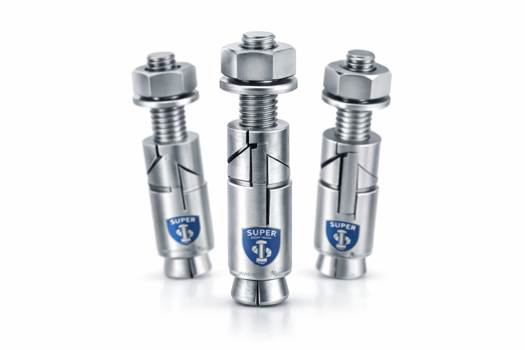
Expansion Bolts are a core component within structural anchoring systems used for transferring loads from steel elements, equipment bases, and structural attachments into hardened concrete substrates. Their application spans across permanent and semi-permanent installations where post-installed anchoring is required.
Primary Structural Applications
Expansion Bolts are used in:
- Reinforced concrete structures
- Beam-to-base connections
- Secondary steel attachments
- Industrial foundations
- Machine base plates
- Pump skids and rotating equipment
- Steel structure anchoring
- Column base fixing
- Support frames
- Oil & gas installations
- Pipe racks
- Compressor foundations
- Power plants
- Turbine auxiliaries
- Cable tray supports
- Infrastructure projects
- Bridge parapets
- Metro rail systems
- Tunnel installations
- Heavy machinery anchoring
- Dynamic load equipment
- Vibration-sensitive installations
Selection Rationale in EPC Environments
Expansion Bolts are selected over alternative anchoring systems based on the following engineering considerations:
| Criteria | Expansion Bolts | Cast-in Anchors | Chemical Anchors |
|---|---|---|---|
| Installation Stage | Post-installed | Pre-concrete | Post-installed |
| Load Transfer | Immediate | High | High |
| Installation Time | Fast | Slow (requires planning) | Moderate |
| Inspection Visibility | High | Low | Medium |
| Load Reliability | Consistent | High | Installation dependent |
| Environmental Sensitivity | Low | Low | High (temperature, curing) |
Why Expansion Bolts Are Preferred
- No dependency on curing time
- Immediate load application capability
- Minimal installation variables
- Suitable for retrofit and brownfield projects
- Predictable mechanical behavior under load
Technical Definition
Expansion Bolts are mechanical anchoring fasteners designed to develop load resistance through radial expansion forces within a pre-drilled hole in a concrete substrate.
Core Functional Characteristics
- Operate on friction-based load transfer
- Utilize mechanical expansion mechanisms
- Installed in pre-drilled and cleaned holes
- Designed for tension, shear, and combined loading
Primary Components
- Threaded bolt or stud
- Expansion sleeve or clip
- Cone or wedge element
- Nut and washer (external load application)
Types of Expansion Bolts
1. Wedge Anchors
- Torque-controlled expansion
- High load capacity
- Suitable for cracked and uncracked concrete
2. Sleeve Anchors
- Full-length expansion sleeve
- Moderate load capacity
- Suitable for lighter structural applications
3. Shield Anchors
- Multi-segment expansion mechanism
- Suitable for masonry and low-strength concrete
4. Drop-in Anchors
- Internally threaded
- Installed flush with surface
- Used for suspended systems
5. Through Bolts
- Pre-assembled anchor system
- Installed through fixture into base material
- Suitable for rapid installation
Engineering & Load Transfer Principle
Radial Expansion Mechanism
Expansion Bolts function through controlled radial expansion of a sleeve or clip against the internal wall of a drilled hole.
Installation sequence:
- Hole is drilled to specified diameter and depth
- Anchor is inserted into the hole
- Torque is applied to the nut or bolt head
- Cone is pulled into the expansion sleeve
- Sleeve expands radially against concrete
Friction vs Mechanical Interlock
Expansion Bolts transfer loads through:
Frictional Resistance
- Generated by contact pressure between sleeve and concrete
- Dependent on:
- Surface roughness
- Expansion force
- Concrete strength
Mechanical Interlock
- Achieved through deformation of concrete
- Secondary contribution to load resistance
Contact Pressure Development
The expansion process generates:
- Radial stress in concrete
- Normal force between anchor and hole wall
- Frictional resistance proportional to applied torque
Hole Diameter vs Bolt Diameter Relationship
| Parameter | Engineering Requirement |
|---|---|
| Hole Diameter | Equal to anchor nominal diameter |
| Tolerance | Typically +0.5 mm |
| Oversized Hole | Reduces frictional resistance |
| Undersized Hole | Prevents proper installation |
3.Expansion Force Generation
Expansion force is a function of:
- Applied installation torque
- Thread pitch
- Friction coefficient
- Cone geometry
Load Transfer into Concrete
Load path:
Bolt → Expansion Sleeve → Contact Pressure → Concrete Mass
Failure Modes of Expansion Bolts
Understanding failure modes is critical for design validation and EPC evaluation.
1. Concrete Cone Failure
- Formation of a conical fracture surface
- Occurs under tensile loading
- Influenced by embedment depth and spacing
2. Pull-Out Failure
- Anchor slips without concrete failure
- Caused by insufficient expansion or low friction
3. Steel Failure
- Yielding or fracture of bolt
- Occurs when steel strength is lower than anchorage capacity
4. Edge Failure
- Concrete breaks at edge due to insufficient edge distance
5. Splitting Failure
- Concrete cracks due to excessive radial stress
- Common in low edge distance or thin members
Load & Performance Engineering
Tensile Load Capacity
Dependent on:
- Embedment depth
- Concrete compressive strength
- Anchor diameter
- Installation torque
Shear Load Capacity
Controlled by:
- Bolt cross-sectional area
- Edge distance
- Concrete strength
Combined Loading
Simultaneous tension and shear require interaction checks based on design standards.
Static vs Dynamic Loads
| Load Type | Consideration |
|---|---|
| Static | Standard design values |
| Dynamic | Requires fatigue consideration |
| Impact | Requires higher safety factor |
Vibration Resistance
- Wedge anchors perform better under vibration
- Locking mechanisms or thread locking may be required
Seismic Considerations
- Requires compliance with anchoring design codes
- Ductility and displacement capacity are critical
Safety Factors
Typical engineering practice:
- Tensile safety factor: 3 to 5
- Shear safety factor: 2 to 4
Edge Distance & Spacing Impact
Reduction factors apply when:
- Anchors are installed close to edges
- Multiple anchors are installed in proximity
Dimensional & Design Logic
Key Design Parameters
| Parameter | Description |
|---|---|
| Anchor Diameter | Nominal bolt size |
| Embedment Depth | Depth of anchorage |
| Hole Diameter | Drill size |
| Effective Anchorage Depth | Load-bearing depth |
| Edge Distance | Distance from concrete edge |
| Spacing | Distance between anchors |
Thread Standards
- Metric threads (ISO)
- UNC/UNF (for export applications)
Tolerance Classes
- Thread tolerance: 6g / 6H
- Hole tolerance: Controlled for friction reliability
Surface Finish Impact
Surface condition influences:
- Friction coefficient
- Corrosion resistance
- Long-term performance
Super Industries
Global Manufacturer of Heavy & Custom Engineered Fasteners & Flanges
4. Applicable Standards (ASTM / DIN / ISO / EN)
Expansion Bolts used in structural anchoring applications are governed by a combination of material standards, dimensional standards, and design codes. In EPC environments, compliance is evaluated based on application conditions, load requirements, and inspection protocols.
Structural & Design Standards
EN 1992-4 (Anchoring in Concrete)
Primary European design standard governing:
- Load calculation methods
- Failure mode evaluation
- Edge distance and spacing requirements
- Partial safety factors
Applicable for:
- Cracked and uncracked concrete
- Static and seismic loading conditions
- Design validation in EPC and consultant-reviewed projects
ASTM Standards (Material & Mechanical Properties)
ASTM F1554
- Standard specification for anchor bolts used in concrete
- Grades: 36, 55, 105
- Defines yield strength and tensile properties
- Common in structural anchoring systems in infrastructure and industrial projects
ASTM A307
- Low carbon steel bolts
- Suitable for general-purpose anchoring
- Limited use in high-load applications
ASTM A193 Grade B7
- Alloy steel, heat-treated
- High tensile strength
- Suitable for:
- High-pressure environments
- Elevated temperature conditions
- Oil & gas installations
DIN Standards (Dimensions & Fastener Geometry)
DIN 933
- Hex bolts (fully threaded)
- Used in expansion anchor assemblies
DIN 125
- Flat washers
- Load distribution and surface protection
DIN 571
- Threaded fasteners (reference for geometry in some anchoring systems)
ISO Standards
- ISO metric thread standards
- ISO tolerance classes (6g / 6H)
- ISO material equivalence references
Standards Mapping to Application
| Application Condition | Recommended Standard |
|---|---|
| Structural anchoring (EU projects) | EN 1992-4 |
| General anchoring (US projects) | ASTM F1554 |
| High-temperature / pressure | ASTM A193 B7 |
| General industrial fastening | ASTM A307 |
| Dimensional compliance | DIN / ISO |
Material & Grade Options
Material selection for Expansion Bolts is driven by load requirements, environmental exposure, and service conditions.
Carbon Steel
Characteristics:
- Moderate strength
- Cost-effective
- Suitable for indoor and non-corrosive environments
Limitations:
- Requires surface protection for corrosion resistance
Stainless Steel
SS304
- Good corrosion resistance
- Suitable for outdoor and mildly corrosive environments
SS316
- Enhanced corrosion resistance
- Suitable for:
- Marine environments
- Chemical exposure
- Coastal infrastructure
Alloy Steel
- High strength material
- Typically heat-treated (quenched & tempered)
- Used for high-load and critical anchoring applications
Material Comparison Table (Mandatory)
| Grade | Yield Strength (MPa) | Tensile Strength (MPa) | Corrosion Resistance | Temperature Range | Typical Application |
|---|---|---|---|---|---|
| ASTM A307 | ~250 | 400–550 | Low | -20°C to 200°C | General anchoring |
| ASTM F1554 Gr 36 | 250 | 400–550 | Low | -20°C to 200°C | Structural anchoring |
| ASTM F1554 Gr 55 | 380 | 520–700 | Low | -20°C to 300°C | Medium load structures |
| ASTM A193 B7 | 720 | 860–1000 | Moderate (with coating) | -29°C to 450°C | Oil & gas, high load |
| SS304 | 215 | 505–700 | High | -50°C to 400°C | Outdoor applications |
| SS316 | 205 | 515–700 | Very High | -50°C to 450°C | Marine & chemical |
Material Selection Logic
| Condition | Recommended Material |
|---|---|
| Indoor / dry | Carbon steel |
| Outdoor exposure | SS304 |
| Marine / coastal | SS316 |
| High load / high temp | ASTM A193 B7 |
5. Heat Treatment Information
Heat treatment is applied to improve mechanical strength, hardness, and fatigue resistance of Expansion Bolts, particularly for alloy steel grades.
Quenching & Tempering
Process:
- Heating to austenitizing temperature
- Rapid cooling (quenching)
- Reheating to controlled temperature (tempering)
Outcome:
- Increased tensile strength
- Improved toughness
- Controlled hardness
Case Hardening (Selective Applications)
- Surface hardening while maintaining ductile core
- Improves wear resistance of threads
Stress Relieving
- Reduces residual stresses after forming or machining
- Prevents distortion and cracking
Hardness Ranges
| Material | Hardness (HRC) |
|---|---|
| Carbon Steel | 15 – 25 |
| Alloy Steel (B7) | 25 – 35 |
| Stainless Steel | 15 – 30 |
Microstructure Considerations
- Tempered martensite for alloy steel
- Ferritic/pearlitic structure for carbon steel
- Austenitic structure for stainless steel
Microstructure directly influences:
- Strength
- Ductility
- Fatigue resistance
Manufacturing Process
Manufacturing of Expansion Bolts follows a controlled sequence to ensure dimensional accuracy, mechanical reliability, and traceability.
Raw Material Inspection
- Chemical composition verification
- Mechanical property validation
- Mill test certificate review
Cutting & Forming
- Bar cutting to required length
- Hot or cold forging (depending on size)
- Head formation (if applicable)
Thread Rolling
- Cold thread rolling process
- Improves:
- Surface finish
- Fatigue strength
- Dimensional accuracy
Sleeve Manufacturing
- Tube cutting and slotting
- Precision expansion geometry control
- Surface conditioning
Assembly
- Cone, sleeve, and bolt assembled
- Washer and nut installation
- Alignment verification
Heat Treatment
- Applied based on grade requirements
- Controlled furnace cycles
- Hardness verification
Surface Coating
- Zinc plating / galvanizing / PTFE
- Thickness control
- Adhesion verification
Final Inspection
- Dimensional verification
- Thread gauge inspection
- Visual inspection
Marking & Traceability
- Batch marking
- Heat number traceability
- Grade identification
6. Surface Finish Options
Surface finish is critical for corrosion resistance and long-term performance of Expansion Bolts.
Zinc Plating
- Electroplated zinc coating
- Suitable for indoor applications
- Moderate corrosion resistance
Hot-Dip Galvanizing (HDG)
- Thick zinc coating (50–85 microns)
- Suitable for outdoor and industrial environments
Mechanical Galvanizing
- Uniform coating without hydrogen embrittlement
- Suitable for high-strength bolts
PTFE Coating
- Low friction coefficient
- Chemical resistance
- Suitable for aggressive environments
Black Oxide
- Minimal corrosion resistance
- Used for indoor applications
Passivation (Stainless Steel)
- Enhances corrosion resistance
- Removes free iron from surface
Corrosion Protection Comparison
| Coating | Corrosion Resistance | Typical Use |
|---|---|---|
| Zinc Plating | Moderate | Indoor |
| HDG | High | Outdoor |
| Mechanical Galvanizing | High | Structural |
| PTFE | Very High | Chemical |
| Black Oxide | Low | Indoor dry |
| Passivation | High | Stainless steel |
7. Inspection & Quality Control Methods
Expansion Bolts used in EPC and structural anchoring applications are subject to multi-stage inspection to verify dimensional accuracy, mechanical performance, and installation reliability.
Dimensional Inspection
Verification parameters:
- Anchor diameter
- Thread pitch and profile
- Sleeve dimensions
- Overall length
- Embedment marking (if applicable)
Tools used:
- Vernier calipers
- Micrometers
- Thread gauges
Proof Load Testing
- Conducted to validate tensile capacity
- Load applied to a specified percentage of yield strength
- No permanent deformation permitted
Pull-Out Testing
- Simulates field anchoring conditions
- Anchor installed in concrete block
- Tensile load applied until failure
Used to evaluate:
- Load capacity
- Failure mode
- Installation reliability
Torque Testing
- Confirms installation torque vs expansion behavior
- Ensures proper sleeve expansion
Coating Thickness Testing
- Measured using coating thickness gauges
- Required for galvanized and plated finishes
Hardness Testing
- Rockwell hardness testing (HRC scale)
- Ensures compliance with heat treatment requirements
Thread Gauge Inspection
- GO / NO-GO gauges
- Ensures thread compatibility and fit
Third-Party Inspection (TPI)
Common agencies:
- SGS
- BV
- TUV
Verification includes:
- Raw material traceability
- Mechanical testing
- Coating validation
- Documentation review
Certification
- EN 10204 3.1 (Mill Test Certificate)
- EN 10204 3.2 (Third-party verified certificate)
A. TECHNICAL DIMENSION TABLE – EXPANSION BOLTS
| Anchor Size | Hole Diameter (mm) | Embedment Depth (mm) | Thread Length (mm) | Sleeve Length (mm) |
|---|---|---|---|---|
| M8 | 8 | 50 – 60 | 25 | 35 |
| M10 | 10 | 60 – 75 | 30 | 40 |
| M12 | 12 | 75 – 90 | 35 | 50 |
| M16 | 16 | 90 – 110 | 45 | 65 |
| M20 | 20 | 110 – 130 | 55 | 80 |
| M24 | 24 | 130 – 160 | 65 | 95 |
Engineering Notes
- Hole diameter must match anchor diameter
- Embedment depth directly influences tensile capacity
- Sleeve length governs expansion contact area
B. LOAD CAPACITY TABLE (REFERENCE VALUES)
(Based on standard concrete strength ~25 MPa, safety factors included)
| Size | Tensile Load (kN) | Shear Load (kN) |
|---|---|---|
| M8 | 6 – 8 | 5 – 6 |
| M10 | 10 – 12 | 8 – 10 |
| M12 | 15 – 18 | 12 – 14 |
| M16 | 25 – 30 | 20 – 24 |
| M20 | 40 – 50 | 30 – 36 |
| M24 | 60 – 75 | 45 – 55 |
Engineering Considerations
- Values reduce for cracked concrete
- Edge distance and spacing reduce capacity
- Installation quality directly affects performance
C. TORQUE CHART (MANDATORY)
Torque values are critical for proper expansion and load development.
| Size | Torque (Nm) – Carbon Steel | Torque (Nm) – Lubricated | Torque (Nm) – B7 Alloy |
|---|---|---|---|
| M8 | 20 – 25 | 15 – 18 | 25 – 30 |
| M10 | 40 – 50 | 30 – 38 | 50 – 60 |
| M12 | 70 – 90 | 55 – 70 | 90 – 110 |
| M16 | 150 – 180 | 120 – 150 | 180 – 220 |
| M20 | 280 – 320 | 220 – 260 | 320 – 380 |
| M24 | 450 – 520 | 360 – 420 | 520 – 600 |
Torque Engineering Notes
- Under-torque → insufficient expansion
- Over-torque → thread damage or concrete cracking
- Lubrication reduces friction and required torque
D. PULL-OUT CALCULATION GUIDE (MANDATORY)
Basic Pull-Out Resistance Formula
Where:
- ( P ) = Pull-out load (N)
- ( \tau ) = Bond / friction stress (N/mm²)
- ( d ) = Anchor diameter (mm)
- ( h ) = Embedment depth (mm)
Concrete Strength Influence
- Higher concrete grade → higher bond stress
- Typical values:
| Concrete Grade | Bond Stress (MPa) |
|---|---|
| M20 | 1.2 – 1.5 |
| M25 | 1.5 – 2.0 |
| M30 | 2.0 – 2.5 |
Embedment Depth Relationship
- Pull-out resistance is linearly proportional to embedment depth
- Increasing depth increases load capacity
Sample Engineering Calculation
Given:
- Anchor diameter = 12 mm
- Embedment depth = 80 mm
- Bond stress = 1.8 MPa
Calculation:
![\[P = 1.8 \times \pi \times 12 \times 80\]](https://superindustriesindia.in/wp-content/ql-cache/quicklatex.com-6cc68af3e07fb00a7717aa8451791489_l3.png "Rendered by QuickLaTeX.com")
![\[P \approx 5428 \, \text{N} \approx 5.4 \, \text{kN}\]](https://superindustriesindia.in/wp-content/ql-cache/quicklatex.com-fc1cbe1e7a1e156b400c3052684a9ba8_l3.png "Rendered by QuickLaTeX.com")
Design Considerations
- Apply safety factor (typically 3–5)
- Reduce load near edges
- Adjust for cracked concrete
E. YIELD STRENGTH CHART (ENGINEERING INTERPRETATION)
Yield strength defines the stress level at which the anchor material begins to deform plastically.
Typical Values
| Grade | Yield Strength (MPa) |
|---|---|
| ASTM A307 | ~250 |
| F1554 Gr 55 | ~380 |
| ASTM A193 B7 | ~720 |
| SS304 | ~215 |
| SS316 | ~205 |
Engineering Implication
- Higher yield strength → higher load capacity
- Must be balanced with ductility requirements
- Critical for seismic and dynamic applications
F. MECHANICAL PROPERTY TABLE
| Material | Yield Strength (MPa) | Tensile Strength (MPa) | Hardness (HRC) | Elongation (%) |
|---|---|---|---|---|
| Carbon Steel | 250 – 380 | 400 – 600 | 15 – 25 | 20 – 25 |
| Alloy Steel (B7) | ~720 | 860 – 1000 | 25 – 35 | 12 – 16 |
| SS304 | ~215 | 505 – 700 | 15 – 25 | 35 – 45 |
| SS316 | ~205 | 515 – 700 | 15 – 25 | 30 – 40 |
Interpretation
- Alloy steel provides high strength but lower elongation
- Stainless steel provides high ductility and corrosion resistance
G. CORROSION RESISTANCE TABLE
| Environment | Carbon Steel (Plated) | HDG | SS304 | SS316 |
|---|---|---|---|---|
| Indoor | Suitable | Suitable | Suitable | Suitable |
| Outdoor | Limited | Suitable | Suitable | Suitable |
| Marine | Not recommended | Moderate | Moderate | Suitable |
| Chemical Exposure | Not suitable | Limited | Moderate | Suitable |
Engineering Notes
- Coating selection must align with service environment
- Stainless steel preferred for long-term durability in corrosive conditions
ADDITIONAL ENGINEERING GUIDANCE
Effect of Installation Variables on Performance
| Variable | Impact |
|---|---|
| Hole cleanliness | Directly affects friction |
| Torque accuracy | Controls expansion force |
| Concrete strength | Governs load capacity |
| Edge distance | Prevents failure modes |
Typical Failure Due to Installation Errors
- Improper hole diameter
- Dust or debris inside hole
- Incorrect torque application
- Insufficient embedment depth
8. Industries Served
Expansion Bolts are deployed across multiple heavy engineering sectors where post-installed anchoring systems are required for structural load transfer into concrete. Selection is governed by load conditions, environmental exposure, and installation constraints.
Oil & Gas Sector
Applications include:
- Pipe rack anchoring systems
- Skid-mounted equipment fixing
- Compressor and pump base anchoring
- Offshore module secondary attachments
Engineering Requirements:
- High load-bearing capacity
- Resistance to vibration and cyclic loads
- Compatibility with high-strength materials (e.g., ASTM A193 B7)
- Corrosion protection for offshore and coastal exposure
Power Plants
Used in:
- Turbine auxiliary systems
- Cable tray supports
- Structural frames and platforms
- Switchyard equipment anchoring
Performance Considerations:
- Thermal expansion compatibility
- Long-term load stability
- Resistance to dynamic loading
Infrastructure Projects
Includes:
- Bridges and flyovers
- Metro rail systems
- Tunnel support systems
- Roadside structural installations
Design Factors:
- High reliability under variable loads
- Environmental durability
- Compliance with international anchoring codes
Steel & Process Plants
Applications:
- Structural steel connections
- Equipment anchoring
- Conveyor systems
- Storage systems
Requirements:
- High shear resistance
- Resistance to industrial corrosion
- Consistent installation performance
Cement Plants
Used for:
- Heavy equipment anchoring
- Kiln and mill support structures
- Material handling systems
Conditions:
- Dust-intensive environment
- High vibration
- Abrasive exposure
Railways & Metro Systems
Applications include:
- Trackside equipment
- Signaling structures
- Platform installations
Key Considerations:
- Dynamic and impact loads
- Fatigue resistance
- Long-term structural stability
Heavy Equipment Installation
Used in:
- Machine foundations
- Industrial presses
- Rotating equipment
Engineering Requirements:
- High tensile and shear strength
- Resistance to vibration loosening
- Controlled installation torque
9. Export Capability & Global Supply
Super Industries operates as a manufacturer and exporter of Expansion Bolts for global EPC and infrastructure projects, with supply aligned to international documentation and compliance requirements.
Regions Served
- United States
- European Union
- Middle East (UAE, Saudi Arabia, Qatar, Oman)
- Southeast Asia
- Africa
Export Packaging
Packaging is designed to maintain product integrity during long transit cycles.
Methods include:
- Wooden crates (fumigated, ISPM 15 compliant)
- Palletized packaging
- Moisture-resistant wrapping
- Batch-wise segregation
Documentation
Standard export documentation includes:
- Commercial invoice
- Packing list
- Mill Test Certificates (EN 10204 3.1 / 3.2)
- Third-party inspection reports
- Coating compliance certificates
- Country of origin certificate
Project Supply Capability
- Bulk production for EPC projects
- Lot traceability for each batch
- Custom specification compliance
- Integration with project QA/QC systems
PROCUREMENT & INSTALLATION VIEW
Drilling Procedure
Correct drilling is essential for anchoring performance.
Requirements:
- Rotary hammer drilling (not core cutting)
- Correct drill bit diameter (matching anchor size)
- Controlled drilling depth
Hole Cleaning Requirement
Hole cleaning directly influences friction-based load transfer.
Standard procedure:
- Blow out dust using compressed air
- Brush hole using wire brush
- Repeat air cleaning
Failure to clean hole results in:
- Reduced friction
- Lower pull-out capacity
- Increased risk of anchor failure
Installation Sequence
- Drill hole to required diameter and depth
- Clean hole thoroughly
- Insert Expansion Bolt
- Position fixture
- Apply specified torque
- Verify embedment and alignment
Installation Torque Control
- Torque must be applied using calibrated torque wrench
- Follow torque values specified in Part 3
- Avoid impact tightening tools for final torque
Installation Inspection Checklist
| Parameter | Verification |
|---|---|
| Hole diameter | As per specification |
| Hole depth | Verified |
| Cleanliness | Dust-free |
| Anchor size | Correct |
| Embedment | As required |
| Torque | Within specified range |
| Alignment | Proper |
Common Failure Causes (Field Observations)
- Incorrect hole diameter
- Inadequate cleaning
- Under-torquing or over-torquing
- Insufficient embedment depth
- Installation near edges without design adjustment
- Use in cracked concrete without verification
10. CUSTOM ENGINEERING CAPABILITIES
Project-Specific Manufacturing
Super Industries provides engineering-based customization of Expansion Bolts for project requirements.
Custom Embedment Lengths
- Extended embedment for higher pull-out capacity
- Adjusted designs for thick base plates
Special Coatings
- PTFE for chemical environments
- Heavy galvanizing for offshore use
- Multi-layer coating systems
High-Load Anchors
- Larger diameters (M30 and above)
- High-strength alloy steel variants
- Designed for heavy industrial loads
Application-Specific Design
- Anchors for seismic zones
- Anchors for vibration-sensitive equipment
- Anchors for high-temperature environments
Documentation Support
- Technical datasheets
- Load calculation references
- Material traceability
- Inspection reports
11.QUALITY & CREDIBILITY FRAMEWORK
Engineering Compliance Approach
- Design aligned with EN 1992-4 principles
- Material traceability maintained at batch level
- Inspection aligned with EPC and TPI requirements
- Manufacturing controlled through documented processes
Traceability & Identification
- Heat number marking
- Batch identification
- Grade stamping (where applicable)
Third-Party Inspection Readiness
- Inspection access during production
- Test reports available for review
- Compliance documentation maintained
CONCLUSION
Expansion Bolts function as a mechanically reliable anchoring system for transferring tensile and shear loads into concrete through controlled radial expansion and frictional resistance. Their performance depends on a combination of material properties, installation accuracy, and adherence to anchoring design principles.
From an EPC and structural engineering perspective, evaluation of Expansion Bolts requires:
- Verification of load transfer mechanism
- Assessment of failure modes
- Compliance with applicable standards
- Confirmation of installation procedures
- Validation through testing and inspection
Super Industries manufactures Expansion Bolts in alignment with these engineering requirements, with emphasis on dimensional control, material compliance, and traceability suitable for infrastructure, industrial, and energy sector applications