
TEE NUT INSERTS
Super Industries — “Global Manufacturer of Heavy & Custom Engineered Fasteners for Oil & Gas, Power & EPC Contractors.” — operates as a manufacturer and global exporter of TEE NUT INSERTS engineered for load-bearing threaded connections across industrial, structural, and OEM applications.
1. INDUSTRY CONTEXT & SYSTEM RELEVANCE
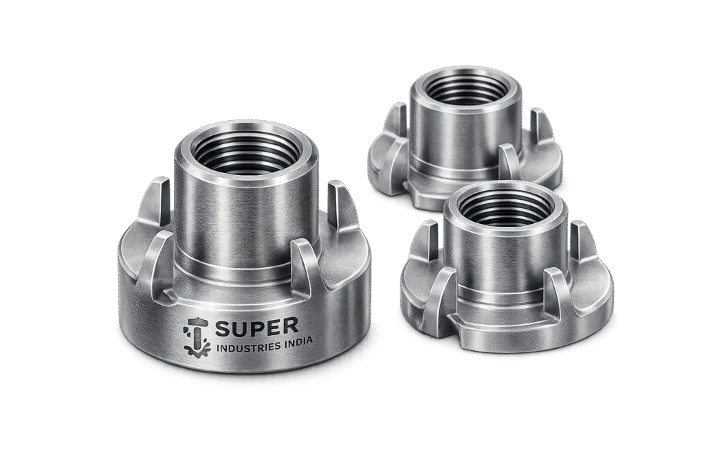
Functional Role in Engineered Assemblies
TEE NUT INSERTS are embedded threaded fastening elements used to create durable, repeatable internal threads within low-strength or non-metallic substrates such as:
- Wood (solid timber, plywood, MDF, particle board)
- Composite panels (HPL, FRP, laminated boards)
- Polymer-based structures
- Sandwich panels (foam core + skins)
- Hybrid assemblies (wood-to-metal interfaces)
They act as load transfer interfaces between:
- A machine-threaded fastener (bolt/screw)
and - A substrate incapable of sustaining direct thread cutting
System-Level Relevance in Engineering Applications
TEE NUT INSERTS are deployed in assemblies where:
| Application Type | Functional Requirement |
|---|---|
| Furniture systems | Repeated assembly/disassembly without thread degradation |
| Modular structures | Fast, aligned installation with consistent preload |
| Industrial enclosures | Secure fastening into panels without cracking |
| OEM products | Embedded fastening in mass production |
| Infrastructure panels | Distributed load transfer in composite materials |
| Automotive interiors | Lightweight fastening with vibration resistance |
Limitation of Direct Threading in Substrates
Direct threading into wood or composites introduces several engineering risks:
A. Low Shear Strength of Substrate
- Wood fibers exhibit anisotropic strength
- Thread stripping occurs under moderate torque
B. Poor Repeatability
- Threads degrade after 2–3 tightening cycles
- Loss of preload leads to joint instability
C. Inconsistent Load Distribution
- Concentrated stress at thread interface
- Local crushing of fibers
D. Alignment Instability
- Fastener misalignment increases eccentric loading
Engineering Justification for TEE NUT INSERTS
TEE NUT INSERTS address these limitations through:
Flange-Based Load Distribution
- Wide flange spreads axial load over larger surface area
- Reduces localized compressive stress
- Improves substrate longevity
Embedded Thread System
- Internal machine threads (ISO metric / UNC / UNF)
- Enables use of high-strength bolts
- Provides consistent torque-preload relationship
Mechanical Anchorage via Prongs
- Multi-prong penetration into substrate
- Prevents rotation (anti-spin mechanism)
- Enhances pull-out resistance
Repeat Assembly Capability
- Thread interface is metallic, not substrate-dependent
- Supports multiple installation cycles without degradation
Load Path Optimization
In a typical TEE NUT assembly:
- Bolt applies axial tensile force
- Load transfers into:
- Internal threads of tee nut
- Barrel body
- Flange distributes load radially into substrate
- Prongs resist rotational and axial displacement
This creates a multi-point load transfer system, unlike direct threading which relies on single interface shear.
2. TECHNICAL DEFINITION
Formal Engineering Definition
TEE NUT INSERTS are:
Flanged, internally threaded, embedded fastening components designed to provide a reusable machine-thread interface within low-strength substrates, incorporating mechanical anchoring features such as prongs or barbs to resist axial and rotational displacement.
Structural Components
A standard TEE NUT INSERT consists of:
A. Flange
- Circular or rectangular base
- Provides surface bearing area
- Acts as load distribution interface
B. Barrel (Body)
- Cylindrical section inserted into substrate
- Houses internal threads
- Determines engagement length
C. Internal Thread
- Metric (M4–M12 typical) or UNC/UNF
- Precision tapped
- Compatible with standard fasteners
D. Prongs / Spikes
- Radial protrusions from flange
- Penetrate substrate during installation
- Provide anti-rotation and retention
Classification by Design Type
Based on Prong Configuration
3-Prong TEE NUT INSERTS
- Balanced load distribution
- Easier insertion in softer materials
- Lower installation force
4-Prong TEE NUT INSERTS
- Higher rotational resistance
- Improved anchorage
- Preferred for high-load applications
Based on Installation Method
Hammer-In Type
- Installed via impact force
- Prongs embed into substrate
- Suitable for wood-based materials
Press-Fit Type
- Installed using controlled pressing
- Ensures uniform penetration
- Used in industrial assembly lines
Based on Base Geometry
Flat Base TEE NUTS
- Standard configuration
- Suitable for general applications
Barrel-Type / Extended Body
- Increased thread engagement length
- Higher pull-out resistance
- Used in thicker substrates
Weldable TEE NUT INSERTS
- Designed for metal-to-metal integration
- Flange modified for weld compatibility
- Eliminates need for prongs
Thread Interface Characteristics
TEE NUT INSERTS provide:
- Controlled pitch accuracy
- Consistent thread engagement
- Compatibility with high-strength bolts (Class 8.8, 10.9, etc.)
- Reduced risk of cross-threading
Thread standards typically include:
- ISO Metric Threads (coarse/fine)
- UNC/UNF (for export markets)
3. ENGINEERING & LOAD TRANSFER PRINCIPLE
Axial Load Transfer Mechanism
When a bolt is tightened:
- Tensile load (F) is generated in the bolt
- Load transfers to:
- Internal thread flank of TEE NUT
- Load continues through:
- Barrel → flange
- Flange distributes load into:
- Substrate surface
Key Principle:
Load is distributed over area, not concentrated at thread interface
Pull-Out Resistance Mechanics
Pull-out resistance depends on:
- Flange diameter
- Substrate density
- Prong penetration depth
- Barrel engagement length
Mechanism:
- Flange resists upward movement
- Prongs provide mechanical interlock
- Friction + material deformation resist extraction
Shear Load Distribution
Shear loads act parallel to substrate surface.
TEE NUT INSERTS resist shear via:
- Friction between flange and substrate
- Bearing resistance of barrel
- Prong anchorage
Engineering Note:
Shear capacity is often governed by substrate strength rather than insert material.
Prong Penetration Mechanics
Prongs function as:
- Localized anchors
- Anti-rotation locks
Penetration Behavior:
- Prongs displace wood fibers
- Create mechanical interlock
- Increase resistance to:
- Rotation (torque)
- Axial pull-out
Torque Resistance Behavior
Torque applied during tightening induces:
- Rotational force on insert
- Potential spin-out if not anchored
TEE NUT INSERTS resist this via:
- Multi-prong engagement
- Surface friction (flange contact)
- Material embedding
Wood Fiber Compression Theory
Wood is a cellular anisotropic material:
- Strong in compression parallel to grain
- Weak in shear perpendicular to grain
TEE NUT INSERT Interaction:
- Flange compresses surface fibers
- Prongs cut into fiber structure
- Load is distributed across compressed region
Thread Engagement vs Insert Strength
Key Relationship:
- Thread strength must exceed substrate strength
- Otherwise failure occurs at substrate level
Design Considerations:
| Parameter | Impact |
|---|---|
| Thread depth | Affects load capacity |
| Pitch | Influences load distribution |
| Engagement length | Controls pull-out strength |
Failure Modes
Pull-Out Failure
- Insert is extracted from substrate
- Occurs due to:
- Low density material
- Insufficient flange area
- Short engagement length
Spin-Out Failure
- Insert rotates under torque
- Caused by:
- Inadequate prong penetration
- Oversized hole
- High tightening torque
Shear Failure
- Occurs under lateral loading
- Substrate cracks or deforms
Thread Stripping
- Internal thread failure
- Rare in steel inserts
- Occurs if bolt strength exceeds insert capacity
Static vs Dynamic Loading Behavior
Static Loads
- Constant load
- Predictable performance
Cyclic Loads
- Repeated tightening/loosening
- Vibration environments
TEE NUT INSERTS provide:
- Stable preload retention
- Reduced degradation vs direct threading
Engineering Summary
TEE NUT INSERTS function as:
- Load distribution devices
- Thread reinforcement systems
- Mechanical anchoring elements
They transform weak substrates into engineered fastening interfaces capable of supporting:
- High axial loads
- Repeated assembly cycles
- Controlled torque application
4. APPLICABLE STANDARDS (ASTM / DIN / ISO / ANSI)
Standards Framework for TEE NUT INSERTS
TEE NUT INSERTS are governed by a combination of:
- Dimensional standards
- Thread standards
- Material specifications
- Inspection & certification protocols
These standards ensure interchangeability, load reliability, and compliance in EPC and OEM applications.
DIN Standards (Primary Reference for T-Nuts)
DIN 1624 / DIN 1625
These standards define:
- Dimensional configuration of TEE NUT INSERTS
- Flange geometry
- Prong configuration
- Thread size compatibility
Engineering Relevance
| Parameter | Standard Control |
|---|---|
| Flange diameter | Ensures load distribution consistency |
| Barrel dimensions | Controls engagement length |
| Prong geometry | Defines anchorage performance |
| Thread alignment | Maintains concentricity |
ISO Thread Standards
ISO Metric Thread System (ISO 261 / ISO 965)
Applicable for:
- M4 to M12 (standard range)
- Coarse and fine pitch threads
Key Controls
- Pitch accuracy
- Thread tolerance class (6H typical)
- Engagement depth
ANSI / ASME Thread Standards
For export markets (US-based systems):
- UNC (Unified National Coarse)
- UNF (Unified National Fine)
Engineering Considerations
| Parameter | Impact |
|---|---|
| Pitch difference | Affects preload characteristics |
| Thread flank angle | Influences load distribution |
| Compatibility | Required for US fasteners |
ASTM Material Standards
TEE NUT INSERTS are manufactured using materials compliant with:
| ASTM Standard | Scope |
|---|---|
| ASTM A1008 | Cold-rolled carbon steel sheet |
| ASTM A1011 | Hot-rolled steel |
| ASTM A276 | Stainless steel bars (SS304 / SS316) |
| ASTM A240 | Stainless steel sheet |
Standard Mapping to Application Environment
| Application | Recommended Standard |
|---|---|
| Furniture systems | DIN + ISO threads |
| Industrial OEM | DIN + ASTM materials |
| Export (US) | ANSI + ASTM |
| Corrosive environments | ASTM SS grades + ISO threads |
EPC Compliance Perspective
For EPC and consultant-level evaluation:
- Thread conformity → ISO/ANSI verified
- Material traceability → ASTM compliant
- Dimensional tolerance → DIN controlled
This ensures:
- Interchangeability across global supply chains
- Predictable load behavior
- Inspection readiness
5. MATERIAL & GRADE OPTIONS
Material Selection Philosophy
Material selection for TEE NUT INSERTS is governed by:
- Load requirements
- Environmental exposure
- Corrosion resistance
- Cost-performance balance
- Compatibility with mating fastener
Carbon Steel TEE NUT INSERTS
Grades Used
- Low Carbon Steel (C15 / C20)
- Case hardenable steels
Characteristics
- Good formability
- Suitable for cold forming
- Cost-effective for high-volume production
Engineering Behavior
- Moderate tensile strength
- Requires surface coating for corrosion protection
- Can be case hardened for wear resistance
Stainless Steel TEE NUT INSERTS
AISI 304
- Austenitic stainless steel
- Good corrosion resistance
- Suitable for indoor and moderate outdoor environments
AISI 316
- Enhanced corrosion resistance (Mo content)
- Suitable for marine, chemical, and humid environments
Alloy Steel Variants (Special Applications)
Used where:
- High load-bearing capacity is required
- Elevated mechanical performance is critical
Characteristics:
- Higher tensile strength
- Heat treatable
- Improved fatigue resistance
Engineering Material Selection Criteria
| Parameter | Carbon Steel | SS304 | SS316 |
|---|---|---|---|
| Strength | Moderate | Moderate | Moderate |
| Corrosion Resistance | Low (needs coating) | Medium | High |
| Cost | Low | Medium | High |
| Application | Indoor / coated systems | General purpose | Marine / chemical |
MATERIAL COMPARISON TABLE
| Grade | Yield Strength (MPa) | Tensile Strength (MPa) | Hardness (HV) | Corrosion Resistance | Typical Application |
|---|---|---|---|---|---|
| C15 (Low Carbon Steel) | 190–250 | 300–400 | 120–160 | Low | Furniture, indoor assemblies |
| C20 (Carbon Steel) | 250–300 | 400–500 | 140–180 | Low | Structural panels |
| Case Hardened Steel | Core: 250–350 | Surface: High | 400–700 (surface) | Low | High wear applications |
| SS304 | 210–290 | 500–700 | 150–200 | Medium | General industrial |
| SS316 | 220–300 | 520–720 | 150–210 | High | Marine, chemical |
Compatibility with Fastener Classes
TEE NUT INSERTS must be compatible with:
- Metric bolt classes: 4.6, 8.8, 10.9
- Stainless fasteners: A2-70, A4-70
Engineering Rule
Insert material strength ≥ substrate-controlled failure threshold
6. HEAT TREATMENT INFORMATION
Purpose of Heat Treatment
Heat treatment enhances:
- Surface hardness
- Wear resistance
- Thread durability
- Load-bearing capacity
Case Hardening (Carburizing)
Process
- Carbon diffusion into surface layer
- Followed by quenching
Result
- Hard outer layer
- Tough ductile core
Typical Hardness
- Surface: 400–700 HV
- Core: 150–250 HV
Quenching & Tempering
Applied to alloy steels:
- Improves strength and toughness
- Reduces brittleness
Stress Relieving
- Removes residual stresses from forming
- Prevents distortion during use
Engineering Importance
| Property | Impact |
|---|---|
| Surface hardness | Improves thread life |
| Core toughness | Prevents brittle failure |
| Wear resistance | Supports repeated assembly |
7. MANUFACTURING PROCESS
Raw Material Selection
- Steel sheets or coils (carbon or stainless)
- Verified chemical composition
- Traceable heat numbers
Blanking & Forming
Process
- Sheet metal stamping
- Progressive die forming
Output
- Flange geometry
- Initial barrel shape
Barrel Formation
- Deep drawing or extrusion
- Ensures cylindrical accuracy
- Controls wall thickness
Thread Tapping
- Internal threading using precision taps
- Controlled pitch and tolerance
Inspection
- GO / NO-GO gauges
Prong Formation
- Punching or stamping process
- Controlled angle and length
Engineering Requirement
- Uniform penetration capability
- No cracking at base
Heat Treatment (If Required)
- Case hardening or tempering
- Controlled furnace conditions
Surface Coating
Applied based on application:
- Electroplating
- Chemical treatment
- Passivation (for stainless steel)
Final Inspection
- Dimensional checks
- Thread inspection
- Visual defect analysis
Marking & Traceability
- Batch identification
- Heat number traceability
- Inspection records
Packaging
- Bulk packaging (bags, cartons)
- Export-grade packing
- Moisture protection
SURFACE FINISH OPTIONS
Purpose of Surface Coating
- Corrosion protection
- Surface hardness improvement
- Aesthetic uniformity
- Reduced friction during installation
Common Surface Finishes
Zinc Plating
- Electroplated coating
- Thickness: 5–25 microns
Advantages:
- Basic corrosion resistance
- Cost-effective
Yellow Zinc (Passivated Zinc)
- Chromate conversion coating
Advantages:
- Improved corrosion resistance
- Identification differentiation
Black Oxide
- Chemical conversion coating
Advantages:
- Minimal dimensional change
- Low reflectivity
Limitation:
- Low corrosion resistance
Phosphate Coating
- Provides base for lubrication
Advantages:
- Improved friction characteristics
- Suitable for assembly operations
Hot-Dip Galvanizing
- Thick zinc coating
Advantages:
- High corrosion resistance
Consideration:
- Not common for small inserts due to dimensional impact
Passivation (Stainless Steel)
- Chemical treatment
- Enhances corrosion resistance
Coating Thickness & Performance
| Coating Type | Thickness | Corrosion Resistance |
|---|---|---|
| Zinc | 5–15 µm | Moderate |
| Yellow Zinc | 8–25 µm | Moderate–High |
| Black Oxide | <2 µm | Low |
| Phosphate | 5–10 µm | Low–Moderate |
| HDG | 40–80 µm | High |
Engineering Selection Criteria
| Environment | Recommended Finish |
|---|---|
| Indoor dry | Zinc / Black oxide |
| Humid | Yellow zinc |
| Outdoor | HDG / SS |
| Chemical | SS316 |
A. TECHNICAL DIMENSION TABLES
Standard Dimensional Reference (Metric Series)
The following table provides typical dimensional relationships for TEE NUT INSERTS based on DIN-oriented configurations. Final dimensions vary based on manufacturer tooling and application requirements.
| Thread Size | Flange Diameter (mm) | Barrel Length (mm) | Recommended Hole Size (mm) | Prong Length (mm) |
|---|---|---|---|---|
| M4 | 12 – 14 | 5 – 7 | 5.0 – 5.2 | 2 – 3 |
| M5 | 14 – 16 | 6 – 8 | 6.0 – 6.2 | 2.5 – 3.5 |
| M6 | 16 – 18 | 7 – 9 | 7.0 – 7.2 | 3 – 4 |
| M8 | 18 – 22 | 8 – 11 | 9.0 – 9.2 | 3.5 – 5 |
| M10 | 22 – 26 | 10 – 13 | 11.0 – 11.2 | 4 – 6 |
| M12 | 26 – 32 | 12 – 16 | 13.0 – 13.2 | 5 – 7 |
Dimensional Engineering Considerations
Flange Diameter
- Directly influences load distribution area
- Larger flange → reduced substrate compression
Barrel Length
- Controls thread engagement length
- Increased length → higher pull-out resistance
Hole Size
- Must maintain interference or snug fit
- Oversizing → risk of spin-out failure
Prong Geometry
- Affects anchorage strength
- Must penetrate without substrate cracking
Geometric Tolerances
| Parameter | Requirement |
|---|---|
| Concentricity | ≤ 0.1 mm |
| Perpendicularity (flange to barrel) | ≤ 0.2 mm |
| Thread tolerance | ISO 6H |
| Surface flatness (flange) | ≤ 0.15 mm |
B. LOAD CAPACITY TABLE
Pull-Out Strength vs Substrate Type
Indicative values for engineering estimation (actual values depend on density, moisture, and installation quality).
| Thread Size | MDF (kgf) | Plywood (kgf) | Hardwood (kgf) | Composite Panel (kgf) |
|---|---|---|---|---|
| M4 | 80 – 120 | 100 – 150 | 120 – 180 | 90 – 140 |
| M5 | 120 – 180 | 150 – 220 | 180 – 260 | 140 – 200 |
| M6 | 180 – 260 | 220 – 320 | 260 – 380 | 200 – 300 |
| M8 | 280 – 400 | 350 – 500 | 400 – 600 | 320 – 450 |
| M10 | 400 – 600 | 500 – 750 | 600 – 900 | 450 – 700 |
Engineering Interpretation
- Pull-out strength increases with:
- Substrate density
- Flange diameter
- Barrel length
- Failure typically occurs in:
- Substrate (not insert)
- Prong disengagement
C. TORQUE CHART
Recommended Installation Torque
| Thread Size | Bolt Class | Dry Torque (Nm) | Lubricated Torque (Nm) |
|---|---|---|---|
| M4 | 8.8 | 2.5 – 3.5 | 2.0 – 2.8 |
| M5 | 8.8 | 5 – 6 | 4 – 5 |
| M6 | 8.8 | 8 – 10 | 6 – 8 |
| M8 | 8.8 | 20 – 25 | 16 – 20 |
| M10 | 8.8 | 40 – 50 | 32 – 40 |
| M12 | 8.8 | 70 – 85 | 55 – 70 |
Torque Engineering Considerations
- Excess torque → spin-out failure
- Low torque → insufficient preload
- Lubrication reduces friction → lower torque required
Torque–Preload Relationship
![\[F = \frac{T}{K \cdot d}\]](https://superindustriesindia.in/wp-content/ql-cache/quicklatex.com-047c3812ff26cb229181955bd579e870_l3.png "Rendered by QuickLaTeX.com")
Where:
- (F) = preload force (N)
- (T) = applied torque (Nm)
- (K) = torque coefficient (≈ 0.18–0.25)
- (d) = nominal diameter (m)
D. PULL-OUT CALCULATION GUIDE
Pull-Out Force Formula
![\[F_{\text{pull-out}} = \tau \cdot \pi \cdot d \cdot L_e\]](https://superindustriesindia.in/wp-content/ql-cache/quicklatex.com-afdc224eefed9ee5309fc866a4085b40_l3.png "Rendered by QuickLaTeX.com")
Where:
- ( \tau ) = shear strength of substrate (MPa)
- ( d ) = insert diameter (mm)
- ( L_e ) = effective engagement length (mm)
Engineering Factors
| Parameter | Influence |
|---|---|
| Substrate density | Directly proportional |
| Moisture content | Reduces strength |
| Installation quality | Critical |
| Edge distance | Prevents cracking |
Sample Calculation
Assume:
- Substrate shear strength = 5 MPa
- Insert diameter = 8 mm
- Engagement length = 10 mm
![\[F = 5 \times \pi \times 8 \times 10 \approx 1256 \, \text{N}\]](https://superindustriesindia.in/wp-content/ql-cache/quicklatex.com-142f191cdad59ec9a2ad5fc01ec67430_l3.png "Rendered by QuickLaTeX.com")
Safety Factor Application
| Application Type | Recommended Safety Factor |
|---|---|
| Static load | 2 – 3 |
| Dynamic load | 3 – 5 |
| Critical structures | 5+ |
E. MECHANICAL PROPERTY TABLE
| Material | Yield Strength (MPa) | Tensile Strength (MPa) | Hardness (HV) | Elongation (%) |
|---|---|---|---|---|
| Low Carbon Steel | 190 – 300 | 300 – 500 | 120 – 180 | 20 – 30 |
| Case Hardened Steel | Core: 250 – 350 | Surface: High | 400 – 700 (surface) | 10 – 20 |
| SS304 | 210 – 290 | 500 – 700 | 150 – 200 | 40 – 50 |
| SS316 | 220 – 300 | 520 – 720 | 150 – 210 | 40 – 50 |
F. CORROSION RESISTANCE COMPARISON TABLE
| Material / Coating | Humidity Resistance | Outdoor Exposure | Industrial Environment | Marine Exposure |
|---|---|---|---|---|
| Carbon Steel (Uncoated) | Low | Not suitable | Poor | Not suitable |
| Zinc Plated | Moderate | Limited | Moderate | Low |
| Yellow Zinc | Moderate–High | Moderate | Moderate | Low |
| SS304 | High | Good | Good | Moderate |
| SS316 | Very High | Excellent | Excellent | Excellent |
8. INSPECTION & QUALITY CONTROL METHODS
Thread Inspection
GO / NO-GO Gauging
- Ensures thread accuracy
- Confirms tolerance class (6H)
Pull-Out Testing
Method
- Insert installed in test substrate
- Axial force applied until failure
Output
- Maximum pull-out force
- Failure mode identification
Torque Testing
Procedure
- Controlled torque applied
- Measure:
- Installation torque
- Spin-out torque
Hardness Testing
Methods
- Vickers (HV)
- Rockwell (HRC for hardened surfaces)
Coating Thickness Testing
Methods
- Magnetic thickness gauge
- X-ray fluorescence (XRF)
Dimensional Inspection
Measured parameters:
- Flange diameter
- Barrel length
- Hole tolerance compatibility
- Prong geometry
Visual & Surface Inspection
Checks include:
- Burrs
- Cracks
- Coating defects
- Thread damage
Third-Party Inspection
TEE NUT INSERTS may be inspected by:
- Independent inspection agencies
- EPC-appointed inspectors
Certification
EN 10204 Standards
| Type | Description |
|---|---|
| 3.1 | Manufacturer test certificate |
| 3.2 | Third-party verified certificate |
Traceability System
- Batch number tracking
- Heat number linkage
- Inspection record retention
PROCUREMENT & INSTALLATION VIEW (ENGINEERING PERSPECTIVE)
Hole Preparation
- Drill perpendicular to surface
- Maintain tolerance
- Avoid oversized holes
Installation Methods
Hammer-In Installation
- Suitable for wood
- Controlled impact required
Press-Fit Installation
- Preferred for precision assemblies
- Ensures uniform prong penetration
Alignment Control
- Ensure perpendicular insertion
- Avoid angular misalignment
Torque Limits
- Follow recommended torque charts
- Avoid over-tightening
Reusability
- Threads allow multiple assembly cycles
- Substrate condition governs lifespan
Inspection Checkpoints
- Proper seating of flange
- Full prong penetration
- No rotation during tightening
Storage Conditions
- Dry environment
- Avoid corrosion exposure
- Maintain coating integrity
9. INDUSTRIES SERVED
Functional Deployment Across Sectors
rates must be converted into repeatable, load-capable threaded interfaces. Their selection is driven by structural requirements, assembly frequency, and load conditions rather than application aesthetics.
Furniture Manufacturing Systems
Application Scope
- Knock-down (KD) furniture systems
- Modular cabinetry
- Institutional furniture (schools, offices, healthcare)
- Flat-pack assembly systems
Engineering Requirement
- Repeated assembly without thread degradation
- Controlled preload in wood-based substrates
- Resistance to loosening under cyclic loading
TEE NUT INSERT Function
- Converts wood panels into machine-thread-compatible joints
- Maintains consistent torque–tension relationship
- Prevents stripping common in direct wood screws
Modular Construction & Prefabricated Structures
Application Scope
- Pre-engineered building panels
- Modular housing systems
- Interior partition systems
Engineering Requirement
- Fast on-site assembly
- Alignment accuracy
- Structural reliability across multiple installations
TEE NUT INSERT Function
- Enables standardized fastening interfaces
- Supports disassembly and reconfiguration
- Ensures consistent mechanical performance across modules
Automotive Interior Systems
Application Scope
- Seat structures (non-critical load zones)
- Dashboard supports
- Interior panel fastening
Engineering Requirement
- Lightweight fastening systems
- Resistance to vibration and cyclic loads
- Compatibility with composite and polymer substrates
TEE NUT INSERT Function
- Provides metal-thread interface within lightweight materials
- Improves durability under vibration conditions
Electrical & Industrial Enclosures
Application Scope
- Control panels
- Switchgear cabinets
- Equipment housings
Engineering Requirement
- Secure fastening into sheet-backed composite panels
- Repeat maintenance access
- Electrical safety (no loose connections)
TEE NUT INSERT Function
- Maintains fastening integrity during repeated servicing
- Prevents panel damage due to repeated screw insertion
Industrial OEM Assemblies
Application Scope
- Equipment frames
- Machine housings
- Component mounting systems
Engineering Requirement
- Standardized fastening interface
- Compatibility with automated assembly lines
- Predictable torque and preload
TEE NUT INSERT Function
- Enables integration of threaded joints into non-metallic components
- Supports scalable production
Infrastructure & Panel-Based Systems
Application Scope
- Composite infrastructure panels
- Acoustic panels
- Structural cladding systems
Engineering Requirement
- Load distribution across large surface areas
- Resistance to environmental exposure
- Long-term durability
TEE NUT INSERT Function
- Enhances panel fastening strength
- Reduces localized stress concentration
Renewable Energy Structures
Application Scope
- Solar panel mounting (secondary structures)
- Equipment housings in renewable installations
Engineering Requirement
- Corrosion resistance
- Long service life
- Structural reliability under environmental exposure
TEE NUT INSERT Function
- Provides corrosion-resistant fastening interfaces (SS variants)
- Ensures durability in outdoor conditions
10. EXPORT CAPABILITY & GLOBAL SUPPLY
Export-Oriented Manufacturing Approach
Super Industries manufactures TEE NUT INSERTS aligned with:
- International dimensional standards (DIN / ISO)
- Global thread compatibility (Metric, UNC, UNF)
- Material traceability requirements (ASTM compliance)
Regions Served
Supply capability extends to:
- North America (USA, Canada)
- European Union (Germany, France, Italy, Netherlands)
- Middle East (UAE, Saudi Arabia, Qatar)
- Southeast Asia (Singapore, Malaysia, Indonesia, Vietnam)
- Africa (project-based EPC supply)
Packaging Standards
Industrial Packaging
- Bulk polybag packaging
- Corrugated export cartons
- Palletized shipments
Protection Measures
- Moisture-resistant packaging
- Anti-corrosion lining (VCI where required)
- Batch identification labeling
Documentation Support
Supplied documentation includes:
- Material Test Certificates (MTC)
- EN 10204 3.1 / 3.2 certification
- Dimensional inspection reports
- Coating thickness reports
- Heat treatment records
OEM & Private Label Capability
- Custom branding (OEM stamping)
- Part numbering as per client specification
- Barcode and traceability integration
Logistics & Supply Chain Integration
- Containerized shipments (FCL / LCL)
- Export-compliant packaging
- Coordination with EPC logistics schedules
11. PROCUREMENT & INSTALLATION VIEW (EPC & OEM PERSPECTIVE)
Procurement Considerations
Technical Evaluation Parameters
| Parameter | Requirement |
|---|---|
| Thread standard | ISO / ANSI compliance |
| Material grade | Certified (ASTM traceable) |
| Coating | Environment-specific |
| Dimensional tolerance | DIN-aligned |
| Load capacity | Verified via testing |
Supplier Qualification Criteria
- Manufacturing capability (forming, tapping, heat treatment)
- Inspection infrastructure
- Traceability systems
- Export documentation readiness
Installation Engineering Guidelines
Hole Preparation
- Drill diameter must match specified tolerance
- Maintain perpendicular alignment
- Avoid edge proximity to prevent cracking
Installation Method Selection
| Method | Application |
|---|---|
| Hammer-in | Field installation, wood |
| Press-fit | Factory-controlled assembly |
Insertion Requirements
- Full flange seating against surface
- Uniform prong penetration
- No tilting or misalignment
Torque Control
- Follow specified torque chart (Part 3)
- Avoid exceeding substrate capacity
- Apply lubrication where specified
Post-Installation Inspection
- Check for rotation under torque
- Verify flush seating
- Confirm thread engagement
Reusability Considerations
- Thread interface remains stable over multiple cycles
- Substrate integrity determines lifecycle
- Periodic inspection recommended in cyclic applications
Storage & Handling
- Store in dry, controlled environment
- Avoid exposure to moisture (for coated steel)
- Prevent mechanical damage to threads and prongs
12. CUSTOM ENGINEERING CAPABILITIES
Custom Thread Configurations
- Non-standard metric sizes
- UNC / UNF customization
- Fine pitch threads
Flange & Geometry Modifications
- Increased flange diameter for higher load distribution
- Reduced profile designs for space constraints
- Custom shapes for specialized assemblies
Prong Design Variations
- Increased prong count
- Modified penetration angles
- Reinforced anchoring designs
High-Strength Variants
- Alloy steel inserts
- Heat-treated configurations
- Enhanced load-bearing capacity
Surface Coating Customization
- Zinc thickness variation
- Specialized coatings for corrosive environments
- Passivation for stainless steel
OEM-Specific Engineering
- Drawing-based manufacturing
- Prototype development
- Application-specific validation
13. ENGINEERING CONCLUSION
TEE NUT INSERTS function as critical interface components that enable reliable threaded connections in substrates that cannot inherently support threaded fastening.
From an engineering standpoint, their performance is governed by:
- Load distribution through flange geometry
- Anchorage via prong penetration mechanics
- Thread integrity under repeated torque application
- Substrate-dependent failure modes
Their successful application depends on:
- Correct dimensional selection
- Material compatibility
- Controlled installation practices
- Verified load performance
EPC-Level Assessment Outcome
A technically compliant TEE NUT INSERT must demonstrate:
- Conformance to DIN / ISO / ASTM standards
- Verified mechanical performance (pull-out, torque, shear)
- Traceable manufacturing and inspection records
- Suitability for intended environmental conditions
System-Level Value
When correctly specified and installed, TEE NUT INSERTS provide:
- Reliable threaded interfaces in non-metallic substrates
- Repeatable assembly without degradation
- Controlled preload and structural stability
- Compatibility with global fastening systems
Final Engineering Statement
This document establishes that Super Industries, as a manufacturer of TEE NUT INSERTS, operates with:
- Standards-aligned production methodology
- Engineering-driven design control
- Inspection-ready manufacturing systems
- Global supply capability
This aligns with the expectations of:
- EPC contractors
- OEM design engineers
- Procurement and inspection authorities
for technical evaluation and project integration.