
WELD NECK FLANGES
Super Industries
“Global Manufacturer of Heavy & Custom Engineered Fasteners for Oil & Gas, Power & EPC Contractors.”
1. Industry Context & System Relevance
Role of Weld Neck Flanges in Pressure Piping Systems
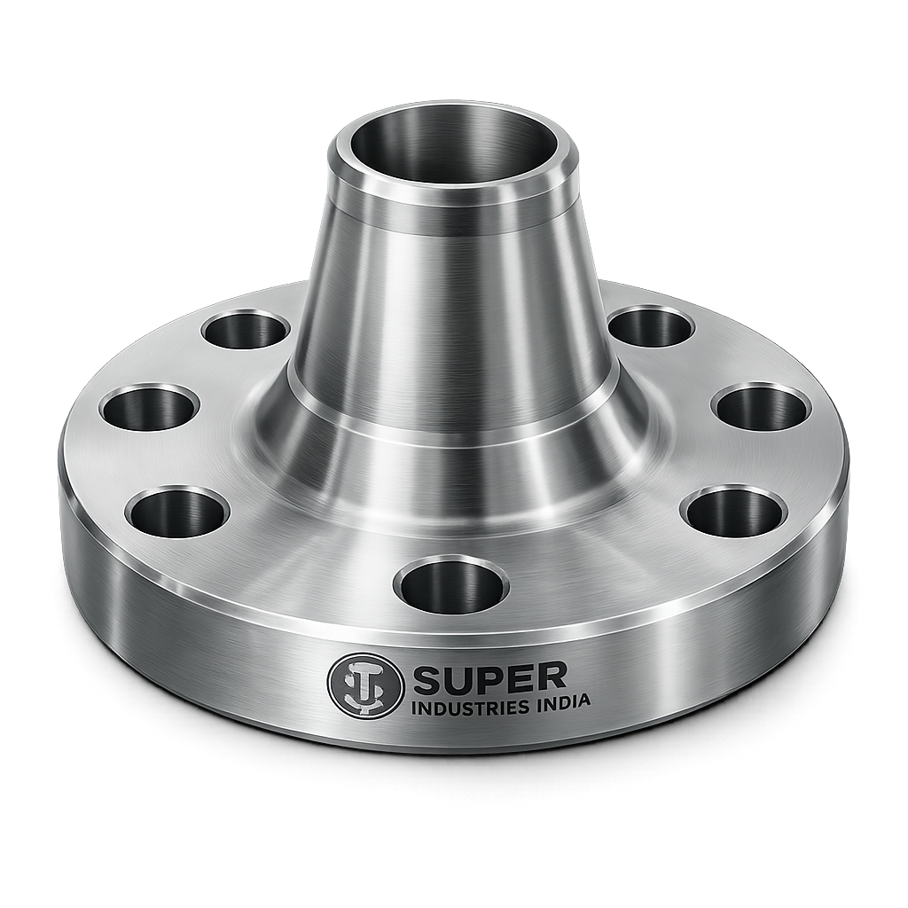
Weld Neck Flanges are structural components used in high-integrity piping systems where continuity of stress flow, pressure containment, and fatigue resistance are critical design requirements. In engineered piping networks, these flanges function as a transition interface between welded piping sections and bolted joint assemblies, ensuring mechanical continuity under combined loading conditions.
In high-pressure and high-temperature systems, flange joints are not only static sealing interfaces but also load-bearing structural elements. The weld neck configuration is specifically designed to reduce stress concentration at the pipe-to-flange transition by introducing a tapered hub that aligns with the pipe wall thickness and allows full penetration butt welding.
This geometry makes Weld Neck Flanges suitable for cyclic and dynamic loading environments, where thermal expansion, vibration, and pressure fluctuations are continuously acting on the system.
Global Application in Critical Process Industries
Weld Neck Flanges are extensively deployed in EPC-driven capital projects where system failure is not permissible due to safety, environmental, or operational constraints.
Typical application sectors include:
- Oil & Gas production facilities (upstream flowlines and wellhead systems)
- Refineries and hydrocarbon processing units
- Petrochemical cracking and reforming units
- LNG liquefaction and regasification terminals
- Thermal and nuclear power generation systems
- Offshore platforms and subsea piping systems
- Hydrogen generation, compression, and distribution networks
- High-pressure steam and boiler systems
In these environments, flange selection is governed by stress analysis, pressure-temperature ratings, and lifecycle fatigue assessment rather than cost optimization alone.
Engineering Justification for Weld Neck Configuration
Within flange engineering, multiple designs exist such as slip-on, threaded, lap joint, and blind flanges. However, Weld Neck Flanges are selected for critical service due to their superior mechanical behavior under combined stress states.
Key engineering reasons include:
- Continuity of Stress Flow: The tapered hub distributes stress gradually from the flange ring into the pipe wall, minimizing discontinuities.
- Reduced Stress Concentration: The butt-welded connection eliminates sharp geometric transitions that typically act as fatigue initiation points.
- High Cyclic Load Resistance: Suitable for thermal cycling and pressure pulsation systems.
- Improved Structural Rigidity: The extended hub increases stiffness at the joint interface.
- Long-Term Integrity: Designed for extended service life under ASME-defined cyclic stress conditions.
Compared to slip-on flanges, where fillet welds introduce localized stress concentration, Weld Neck Flanges provide a more uniform stress distribution path, making them the preferred choice for high-pressure and high-temperature systems.
Fatigue Performance Under Cyclic Loading
In real-world piping systems, loads are rarely static. Pressure fluctuations, thermal gradients, and vibration from rotating equipment induce cyclic stresses.
Weld Neck Flanges demonstrate superior fatigue resistance due to:
- Smooth geometric transition between pipe and flange hub
- Full penetration butt weld eliminating root discontinuities
- Reduced notch sensitivity at weld junction
- Improved load transfer efficiency
Fatigue life is significantly influenced by stress intensity factors at geometric discontinuities. The weld neck design minimizes these factors, thereby improving the allowable number of stress cycles before crack initiation.
Super Industries
Global Manufacturer of Heavy & Custom Engineered Fasteners & Flanges
2. Technical Definition of Weld Neck Flanges
Standard Engineering Definition
A Weld Neck Flange is defined as a forged piping component with a long tapered hub that is butt-welded to a pipe, designed to transfer stresses smoothly into the piping system while providing a bolted sealing interface for system assembly and maintenance.
The flange consists of:
- A circular flange ring with bolt holes
- A raised or ring-type sealing face
- A tapered hub extending from the flange body
- A bore diameter matching the internal diameter of the connecting pipe
Geometric Configuration and Design Logic
The defining feature of Weld Neck Flanges is the tapered hub geometry. This taper is not arbitrary; it is engineered to align with the pipe wall thickness and reduce discontinuity stresses.
Key geometric characteristics include:
- Gradual hub taper transitioning from flange thickness to pipe wall thickness
- Bore alignment with pipe internal diameter to ensure smooth fluid flow
- Controlled weld preparation angle for full penetration butt welding
- Extended hub length for improved stress distribution
The flange bore is typically machined to match the pipe schedule, ensuring hydraulic continuity and minimizing turbulence and pressure losses.
Butt-Welded Structural Integration
The pipe-to-flange connection is achieved through a full penetration butt weld. This welding method ensures:
- Complete fusion across the pipe wall and flange hub
- No internal voids or incomplete fusion zones
- High structural integrity under internal pressure
- Improved fatigue resistance compared to fillet-welded joints
Welding is typically performed in accordance with qualified procedures under ASME Section IX, ensuring weld integrity for pressure-retaining applications.
Stress Flow Continuity Principle
In pressure vessel and piping design, stress continuity is a fundamental requirement. Abrupt changes in geometry lead to localized stress concentration, which can initiate crack formation.
Weld Neck Flanges are designed to maintain:
- Axial stress continuity from pipe to flange hub
- Reduced radial stress gradients
- Controlled bending stress distribution
- Uniform hoop stress transfer
This makes them suitable for high-integrity systems governed by ASME B31.3 (Process Piping) and ASME B31.1 (Power Piping).
Super Industries
Global Manufacturer of Heavy & Custom Engineered Fasteners & Flanges
3. Engineering & Sealing Principles
Load Transfer Mechanism in Flanged Joints
A bolted flange joint operates under a combination of mechanical preload and internal fluid pressure. In Weld Neck Flanges, load transfer occurs through:
- Bolt preload generating gasket compression force
- Internal pressure attempting to separate flange faces
- Flange rigidity resisting rotation and deformation
- Welded joint transferring axial loads into piping system
The welded connection ensures that the flange does not act as an independent structural discontinuity but becomes an integral extension of the pipe.
Gasket Sealing Behavior
Sealing in Weld Neck Flanges is achieved through controlled gasket compression between flange faces. The effectiveness of sealing depends on:
- Bolt preload force
- Gasket material properties
- Flange face finish quality
- Uniform bolt tightening sequence
Common sealing face types include:
Raised Face (RF)
- Most widely used configuration
- Concentrates gasket load on raised sealing area
- Suitable for moderate to high pressure systems
Ring Type Joint (RTJ)
- Metallic sealing system for high-pressure applications
- Used in Class 600 and above systems
- Provides metal-to-metal sealing under extreme conditions
Bolt Preload vs Internal Pressure Interaction
A flanged joint remains leak-tight only when bolt preload exceeds the separating force generated by internal pressure.
Key mechanical relationship:
- Bolt preload generates initial gasket seating stress
- Internal pressure reduces effective gasket compression
- Joint integrity depends on maintaining positive gasket stress under operating conditions
In Weld Neck Flanges, structural rigidity ensures that deformation under load is minimized, preserving gasket compression stability.
Flange Rotation and Structural Behavior
Under pressure loading, flanges tend to rotate slightly due to bending moments. Weld Neck Flanges exhibit lower rotational deformation due to:
- Increased hub stiffness
- Gradual stress distribution
- Reduced localized bending at pipe interface
This results in improved gasket surface contact stability and reduced leakage probability.
Surface Finish and Sealing Performance
Surface roughness of the flange face directly affects gasket sealing efficiency.
Typical requirements:
- Raised Face (RF): Controlled serrated finish for gasket grip
- RTJ grooves: Precision-machined metallic sealing surfaces
- Surface roughness (Ra) typically maintained within ASME B16.5 limits
Improper surface finish can lead to micro-leak paths, even under correct bolt preload conditions.
4. Applicable Standards Governing Weld Neck Flanges
ASME Standards Framework
Weld Neck Flanges used in pressure piping systems are primarily governed by ASME dimensional and material standards. These standards define geometry, pressure-temperature ratings, tolerances, and inspection requirements.
Primary ASME Standards
- ASME B16.5
Governs forged steel flanges up to NPS 24 (600 mm)
Covers:- Pressure classes (150 to 2500)
- Dimensions (OD, BCD, thickness)
- Facing types (RF, RTJ, FF)
- Bolt hole configuration
- ASME B16.47
Applicable for large diameter flanges (NPS 26 to 60)
Used in:- Power plants
- Large diameter pipelines
- LNG trunk lines
- ASME Section VIII Division 1
Governs pressure vessel flange integration - ASME B31.3 / B31.1
Governs piping system design and allowable stress limits
ASTM Material Standards
Material selection for Weld Neck Flanges is defined under ASTM forged product specifications:
- ASTM A105 – Carbon steel forgings (ambient to moderate temperature service)
- ASTM A350 LF2 – Low temperature service (impact tested)
- ASTM A182 F304 / F316 – Austenitic stainless steel
- ASTM A182 F11 / F22 – Alloy steel for high temperature service
- ASTM A182 Duplex / Super Duplex – Corrosion resistant high strength alloys
International Standards Equivalents
| Standard System | Equivalent Specification |
|---|---|
| ASME B16.5 | EN 1092-1 (Europe) |
| ASME Flanges | DIN Standard Flanges |
| ASTM Materials | ISO 3183 / ISO 15614 (supporting weld/material references) |
These equivalencies are critical in EPC global procurement where multi-standard compliance is required.
5. Material Selection & Engineering Suitability
Material Engineering Logic
Material selection for Weld Neck Flanges is governed by:
- Design temperature
- Design pressure
- Corrosive environment
- Hydrogen sulfide (H₂S) exposure
- Chloride content (marine service)
- Cyclic loading severity
Each material grade is selected based on mechanical strength and corrosion resistance balance.
Carbon Steel Grades
ASTM A105 (Standard Carbon Steel Forging)
- Most widely used flange material
- Suitable for ambient to moderate temperature systems
- Excellent machinability and weld compatibility
Limitations:
- Not suitable for cryogenic service
- Limited corrosion resistance
ASTM A350 LF2 (Low Temperature Carbon Steel)
- Designed for sub-zero applications
- Charpy impact tested
- Used in LNG and cryogenic pipelines
Stainless Steel Grades
ASTM A182 F304
- General corrosion resistance
- Suitable for chemical and water systems
- Moderate chloride resistance
ASTM A182 F316
- Molybdenum addition improves pitting resistance
- Suitable for marine and offshore environments
- Preferred in chloride-rich conditions
Alloy Steel Grades
ASTM A182 F11 / F22
- High temperature creep resistance
- Used in:
- Power plant steam lines
- Boiler systems
- Heat exchangers
Duplex & Super Duplex Stainless Steel
- High strength + high corrosion resistance combination
- Excellent resistance to chloride stress corrosion cracking
- Common in offshore and subsea systems
Material Comparison Table
| Material Grade | Yield Strength (MPa) | Tensile Strength (MPa) | Temp Range | Corrosion Resistance | Typical Use |
|---|---|---|---|---|---|
| ASTM A105 | ~250 | 485–620 | -29°C to 425°C | Low | General piping |
| ASTM A350 LF2 | ~240 | 480–655 | -46°C to 345°C | Low | Cryogenic systems |
| ASTM A182 F304 | ~205 | 515–620 | -196°C to 870°C | Medium | Chemical service |
| ASTM A182 F316 | ~205 | 515–620 | -196°C to 870°C | High | Marine / offshore |
| ASTM A182 F11 | ~205 | 485–620 | Up to 550°C | Medium | Power plants |
| Duplex 2205 | ~450 | 620–880 | -50°C to 300°C | Very High | Offshore platforms |
6. Heat Treatment & Metallurgical Control
Purpose of Heat Treatment
Heat treatment is applied to Weld Neck Flanges to:
- Improve mechanical strength
- Relieve residual forging stresses
- Enhance toughness and ductility balance
- Ensure grain structure uniformity
- Achieve compliance with ASTM requirements
Normalizing Process
Used primarily for carbon steel flanges (ASTM A105).
Process:
- Heating above critical temperature (~900–950°C)
- Air cooling
Effects:
- Grain refinement
- Improved toughness
- Uniform microstructure
Quenching & Tempering (Q&T)
Used for alloy steels (A182 F11 / F22).
Process:
- Rapid cooling (quenching)
- Controlled reheating (tempering)
Effects:
- High strength
- Improved hardness control
- Stress reduction
Solution Annealing
Used for stainless steel (F304 / F316).
Process:
- Heating to ~1040–1120°C
- Rapid water cooling
Effects:
- Carbide dissolution
- Corrosion resistance restoration
- Improved ductility
Stress Relieving
Applied after forging or machining:
- Reduces residual stresses
- Improves dimensional stability
- Prevents distortion during service
Mechanical Property Control
Heat treatment directly influences:
- Yield strength
- Tensile strength
- Elongation percentage
- Impact toughness (Charpy V-notch)
These parameters are verified through batch testing under ASTM certification protocols.
7. Manufacturing Process of Weld Neck Flanges
Raw Material Selection & Traceability
- Certified forged billets (ASTM compliant)
- Heat number traceability maintained
- Material test certificates (MTC) verified before production
Forging Process
- Open die or closed die forging
- Grain flow alignment follows flange geometry
- Eliminates internal voids and porosity
Result:
- High structural integrity
- Improved fatigue resistance
Rough Machining
- Initial shaping of OD, hub, and bore
- Removal of forging scale
- Preparation for heat treatment (if required)
CNC Finishing Operations
- Final dimensional accuracy achieved via CNC machining
- Bore machining aligned with pipe schedule
- Face machining for RF or RTJ sealing surface
Hub Profiling
- Tapered hub geometry machined to ASME standards
- Ensures smooth stress transition into pipe
Bolt Hole Drilling
- Precision drilling on bolt circle diameter (BCD)
- Uniform spacing ensures load distribution symmetry
Facing Operations
- Raised Face (RF): serrated finish for gasket grip
- Ring Type Joint (RTJ): precision groove machining
Surface roughness is controlled to ASME-defined Ra values.
Heat Treatment Application
Performed based on material grade:
- Carbon steel → Normalizing
- Alloy steel → Q&T
- Stainless steel → Solution annealing
- Stress relieving → Post-machining stabilization
Surface Finishing
Options include:
- Anti-corrosion oil coating
- Black oxide finish
- Zinc plating
- Phosphate coating
- Hot-dip galvanizing (project-specific)
- Passivation (stainless steel)
Final Inspection & Testing
Each flange undergoes:
- Dimensional inspection (CMM or gauges)
- Hardness testing (Brinell/Rockwell)
- PMI (Positive Material Identification)
- NDT (UT / MPI / DPI depending on specification)
Marking & Traceability
Each Weld Neck Flange is marked with:
- Material grade
- Heat number
- Pressure class
- Size (NPS)
- Manufacturer identification
- ASME standard reference
8. Technical Dimension Framework (ASME B16.5 Basis)
Weld Neck Flanges are dimensionally governed to ensure interchangeability, pressure integrity, and bolt-load uniformity across global piping systems.
Core dimensional parameters include:
- Nominal Pipe Size (NPS)
- Pressure Class
- Outside Diameter (OD)
- Bolt Circle Diameter (BCD)
- Bolt Hole Quantity & Diameter
- Flange Thickness (T)
- Hub Length (H)
- Bore Diameter (matching pipe schedule)
Standard Dimension Table (Extract – Representative EPC Reference)
| NPS | Class | OD (mm) | BCD (mm) | No. of Bolts | Bolt Size | Bore (mm) | Thickness (mm) |
|---|---|---|---|---|---|---|---|
| 1” | 150 | 108 | 79.5 | 4 | M16 | 25.4 | 14 |
| 2” | 150 | 152 | 120.7 | 4 | M16 | 50.8 | 16 |
| 4” | 300 | 229 | 190.5 | 8 | M20 | 101.6 | 24 |
| 6” | 600 | 318 | 279.4 | 12 | M22 | 152.4 | 32 |
| 8” | 900 | 381 | 330.2 | 12 | M27 | 203.2 | 41 |
| 12” | 1500 | 495 | 431.8 | 16 | M33 | 304.8 | 57 |
(Values represent engineering reference alignment under ASME B16.5 system logic.)
Geometric Control Parameters
Weld Neck Flanges require strict geometric tolerances for pressure integrity:
- Concentricity: Bore aligned with flange OD axis
- Perpendicularity: Face to bore axis deviation controlled
- Flatness: Sealing face uniformity within microns
- Surface roughness:
- RF sealing face: controlled serrated finish
- RTJ groove: precision-machined metallic sealing surface
These parameters ensure gasket load distribution remains uniform under bolted preload conditions.
9. Pressure-Temperature Rating System (ASME B16.5)
Pressure Class Definition
Pressure class defines allowable internal pressure at a given temperature. Weld Neck Flanges are categorized into:
- Class 150
- Class 300
- Class 600
- Class 900
- Class 1500
- Class 2500
Pressure Rating Table (Simplified Engineering Reference)
| Class | Cold Working Pressure (PSI) | MPa Equivalent | Typical Temperature Limit |
|---|---|---|---|
| 150 | 285 PSI | 1.97 MPa | Up to 425°C |
| 300 | 740 PSI | 5.1 MPa | Up to 425°C |
| 600 | 1480 PSI | 10.2 MPa | Up to 538°C |
| 900 | 2220 PSI | 15.3 MPa | Up to 538°C |
| 1500 | 3705 PSI | 25.5 MPa | Up to 538°C |
| 2500 | 6170 PSI | 42.5 MPa | Up to 538°C |
Engineering Interpretation
Pressure rating is not absolute; it is governed by:
- Material strength reduction at elevated temperature
- Flange thickness and hub geometry
- Bolt preload capacity
- Gasket sealing limits
As temperature increases, allowable pressure decreases due to material creep and reduced yield strength.
10. Bolt Torque Engineering System
Functional Purpose of Bolt Torque
Bolt torque ensures:
- Initial gasket seating stress
- Controlled flange face compression
- Prevention of leakage under internal pressure
- Load distribution across bolt circle
Incorrect torque leads to:
- Uneven gasket loading
- Flange rotation
- Localized leakage paths
- Bolt yielding or fatigue failure
Torque Calculation Principle
Basic relationship:
- Torque → Bolt preload → Gasket compression → Seal integrity
Engineering expression:
- Bolt preload is proportional to applied torque and inversely affected by friction conditions.
Torque Chart (Industrial Reference Values)
Carbon Steel Bolts (B7 / 8.8 / 10.9) – Lubricated Condition
| Bolt Size | Torque (Nm) | Preload (kN approx.) |
|---|---|---|
| M16 | 80–100 Nm | 45–60 kN |
| M20 | 160–200 Nm | 90–120 kN |
| M24 | 280–350 Nm | 160–210 kN |
| M30 | 550–700 Nm | 300–380 kN |
| M36 | 950–1200 Nm | 520–650 kN |
Dry Condition Adjustment
- Torque increases by ~25–40% due to friction loss
- Lubrication consistency is critical for uniform preload
Bolt Tightening Sequence (Engineering Standard)
Flange bolting must follow cross-pattern tightening:
- Initial snug tightening (30%)
- Intermediate tightening (60%)
- Final torque application (100%)
- Circular re-check pass
This ensures:
- Uniform gasket compression
- Avoidance of flange warping
- Balanced stress distribution
11. Preload & Stress Calculation Framework
Bolt Preload Formula
Axial preload in bolted joints:
- Preload is derived from applied torque and bolt geometry.
Key engineering relationship:
- Bolt stress = Force / Stress area
Axial Force Concept
Internal pressure creates separating force:
- Pressure × Effective gasket area = Joint separating load
Bolt preload must always exceed this force with safety margin.
Safety Factor Philosophy
Typical EPC design safety factors:
- Static systems: 1.5 to 2.0
- Cyclic systems: 2.0 to 3.0
- Critical hydrogen / LNG systems: higher margins depending on code
Engineering Example
For a bolted flange joint:
- Internal pressure generates axial load
- Bolt group resists separation
- Remaining preload maintains gasket compression
Failure occurs when:
- Internal load > residual bolt preload
12. Inspection, Testing & Quality Control Systems
Dimensional Inspection
Ensures compliance with ASME B16.5:
- OD, ID, BCD accuracy
- Bolt hole spacing
- Face flatness
- Hub taper geometry
Non-Destructive Testing (NDT)
Common Methods:
- Ultrasonic Testing (UT)
- Detects internal forging defects
- Magnetic Particle Inspection (MPI)
- Surface and near-surface crack detection
- Dye Penetrant Inspection (DPI)
- Surface flaw detection on machined areas
PMI Testing (Positive Material Identification)
Used to verify alloy composition:
- Confirms ASTM grade compliance
- Prevents material mix-up in EPC projects
- Essential for stainless and alloy steels
Hydrostatic Testing (System Dependent)
- Applied when specified by project
- Verifies pressure containment integrity
- Typically conducted at 1.5× design pressure
Hardness Testing
Ensures material mechanical consistency:
- Brinell / Rockwell methods
- Verifies heat treatment effectiveness
- Prevents over-hardening or brittle failure risk
Third Party Inspection (TPI)
Inspection agencies may include:
- Client representatives
- EPC consultants
- International certification bodies
Deliverables:
- Inspection Release Note (IRN)
- Dimensional reports
- NDT reports
- Material traceability documentation
EN 10204 Certification System
Certification Levels:
- 3.1 Certificate
- Manufacturer declared test results
- Internal quality verification
- 3.2 Certificate
- Third-party witnessed certification
- Required for critical EPC projects
Industries Served (Engineering Application Mapping)
Weld Neck Flanges are classified as critical service pressure-retaining components, and their selection is driven by system integrity requirements rather than cost or availability factors.
Oil & Gas Industry
Upstream Applications
- Wellhead assemblies
- Flowlines and choke manifolds
- High-pressure injection systems
Midstream Applications
- Cross-country pipelines
- Compressor stations
- Metering skids
Downstream Applications
- Refinery process units
- Hydrocracking and reforming units
- Sulfur recovery units
Engineering requirement focus:
- High pressure containment
- Sour service compatibility (H₂S resistance)
- Cyclic load fatigue resistance
Petrochemical & Chemical Processing
Used in:
- Cracking units
- Distillation columns
- Reactor piping systems
Key constraints:
- Chemical corrosion resistance
- Elevated temperature stability
- Sealing reliability under thermal cycling
Power Generation Industry
Applications:
- Boiler feedwater systems
- High-pressure steam lines
- Turbine inlet/outlet piping
Engineering requirements:
- Creep resistance (high temperature exposure)
- Thermal shock tolerance
- High pressure steam containment
LNG & Cryogenic Systems
Applications:
- LNG liquefaction plants
- Regasification terminals
- Cryogenic transfer lines
Material focus:
- ASTM A350 LF2
- Austenitic stainless steels (F304 / F316)
Requirements:
- Low-temperature toughness
- Impact resistance at sub-zero conditions
- Leak-free sealing under contraction cycles
Offshore & Subsea Engineering
Applications:
- Offshore production platforms
- Subsea manifolds
- Riser systems
Design constraints:
- Chloride-induced corrosion resistance
- High fatigue loading due to wave motion
- Extreme environmental exposure
Preferred materials:
- Duplex stainless steel
- Super duplex stainless steel
Hydrogen & Emerging Energy Systems
Applications:
- Hydrogen compression systems
- Electrolyzer interconnections
- Storage and distribution pipelines
Engineering focus:
- Hydrogen embrittlement resistance
- High-pressure sealing reliability
- Material integrity under diffusion exposure
13. Export Capability & Global Supply Chain Readiness
Global Market Coverage
Weld Neck Flanges supplied by EPC-focused manufacturers are typically exported to:
- United States (ASME-driven projects)
- Europe (EN / ISO compliance projects)
- Middle East (oil & gas mega projects)
- Southeast Asia (refinery expansion projects)
- Africa (infrastructure and energy systems)
Export Packaging Engineering
Packaging is designed to ensure:
- Corrosion prevention during transit
- Mechanical protection from impact
- Traceability preservation
Typical packaging systems:
- Wooden fumigated crates (ISPM-15 compliant)
- Plastic protective caps for flange faces
- Anti-corrosion VCI wrapping
- Heat-sealed moisture barriers
Documentation Package for EPC Projects
Each shipment includes:
- Material Test Certificates (MTC – EN 10204 3.1 / 3.2)
- Dimensional inspection reports
- NDT test reports (UT / MPI / DPI)
- PMI reports (when applicable)
- Hydrotest certificates (if specified)
- Heat number traceability records
- Compliance declaration to ASME / ASTM standards
Project Logistics Capability
Export logistics for Weld Neck Flanges typically include:
- FOB / CIF shipment terms
- Containerized and breakbulk shipping
- Heavy cargo consolidation for large diameter flanges
- Coordination with EPC project schedules
- Sequential delivery planning for shutdown projects
Installation Engineering & Field Practices
Butt Welding Procedure (Pipe to Flange Integration)
Weld Neck Flanges are installed using full penetration butt welds.
Key steps:
- Pipe end preparation (beveling)
- Alignment with flange hub
- Tack welding for positioning
- Full circumferential welding
- Multi-pass welding (as per WPS)
- Post weld inspection
Welding compliance:
- ASME Section IX qualified procedures
- Certified welding consumables
- Controlled preheat/post-heat (where required)
Weld Inspection Requirements
Inspection methods include:
- Radiographic Testing (RT)
- Ultrasonic Testing (UT)
- Visual Inspection (VT)
Purpose:
- Detect internal weld discontinuities
- Verify fusion integrity
- Ensure compliance with pressure codes
Flange Joint Assembly Procedure
Proper flange assembly is critical for leak-free operation.
Steps:
- Gasket placement on sealing face
- Bolt insertion in cross pattern
- Progressive tightening sequence (30% → 60% → 100%)
- Final torque verification
- Uniform flange face contact confirmation
Gasket Engineering Considerations
Gasket selection depends on:
- Pressure class
- Temperature range
- Fluid type
Common gasket types:
- Spiral wound gasket (most common)
- RTJ metallic ring gasket
- Graphite-based sealing systems
Bolt Tightening Sequence Logic
Correct tightening pattern:
- Cross diagonal sequence
- Multi-stage tightening
- Torque uniformity control
Failure to follow sequence results in:
- Flange warping
- Uneven gasket compression
- Leakage initiation under pressure
Re-Torque Requirements
Re-torque may be required:
- After thermal cycling
- After initial pressurization
- During maintenance shutdowns
This ensures long-term sealing stability.
Storage & Handling Practices
Weld Neck Flanges must be stored under controlled conditions:
- Dry environment
- Face protection caps installed
- No direct ground contact
- Horizontal stacking for large sizes
Incorrect storage leads to:
- Corrosion pitting
- Face damage
- Misalignment during installation
14. Procurement Engineering View (EPC Evaluation Perspective)
From an EPC procurement standpoint, Weld Neck Flanges are evaluated based on:
Technical Evaluation Parameters
- ASME / ASTM compliance verification
- Material traceability (heat number control)
- Dimensional conformity to B16.5 / B16.47
- Pressure class certification
- NDT and PMI validation
- Third-party inspection acceptance
Manufacturing Qualification Criteria
Approved suppliers must demonstrate:
- Forging capability with controlled grain flow
- CNC machining accuracy for sealing faces
- Heat treatment control system
- Repeatability of dimensional tolerances
- Documentation compliance under EN 10204
Risk Assessment Considerations
EPC engineers evaluate risks such as:
- Material mismatch risk
- Weld failure risk
- Leakage under cyclic loading
- Thermal expansion misalignment
- Improper bolt preload distribution
Weld Neck Flanges are preferred because they minimize these risks structurally.
Commercial vs Engineering Priority Balance
In EPC evaluation:
- Engineering compliance overrides cost advantage
- Lifecycle integrity is prioritized over procurement price
- Certification completeness is mandatory
- Non-conformance leads to immediate rejection in bid stage
Final Engineering Conclusion (EPC Acceptance Statement)
Weld Neck Flanges represent a structurally optimized solution for high-pressure and high-temperature piping systems where failure is not permissible under operational, environmental, or safety constraints.
Their key engineering advantages include:
- Continuous stress flow between pipe and flange
- Superior fatigue resistance under cyclic loading
- High structural rigidity at joint interface
- Reliable gasket sealing under varying pressure conditions
- Full compliance with ASME B16.5 / B16.47 dimensional standards
- Compatibility with global EPC inspection and certification systems
From a procurement and engineering evaluation standpoint, Weld Neck Flanges are classified as critical integrity components, suitable for use in refinery, offshore, LNG, power generation, and hydrogen infrastructure systems where long-term operational reliability is mandatory.