
FLARE FITTINGS
Engineering Reference for US & EU Hydraulic Systems
Manufacturer: Super Industries
https://superindustriesindia.in/
1. Industry Context: Role of Flare Fittings in US and EU Hydraulic Systems
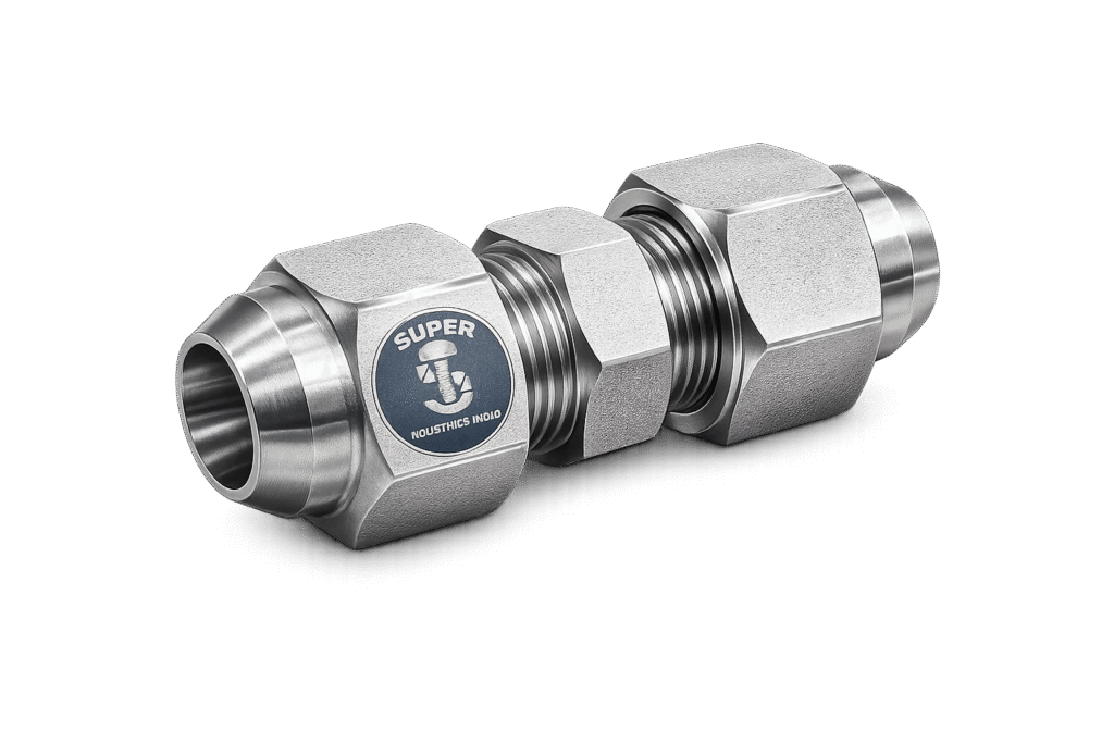
Flare fittings are a foundational connection technology within high-pressure hydraulic and fluid conveyance systems, particularly in North American and internationally aligned industrial frameworks. In regulated piping environments governed by ASME B31.1, ASME B31.3, and the European Pressure Equipment Directive (PED 2014/68/EU), mechanically flared tube connections remain a widely accepted solution for medium- to high-pressure service where dimensional precision and predictable sealing behavior are required.
Within the United States, flare fittings are primarily associated with the SAE J514 37° flare standard, which defines dimensional geometry, performance expectations, and thread configurations for metal-to-metal flare-type tube fittings. Across Europe, the technical equivalent is governed by ISO 8434-2, which harmonizes flare-type fittings under metric and international frameworks. While DIN 2353 compression fittings dominate many continental applications, flare fittings continue to be specified in projects involving US-origin hydraulic equipment, OEM platforms, and multinational skid packages.
1.1 Functional Role in Hydraulic Systems
In a closed-loop hydraulic system, pressure transmission relies on secure tube-to-component connections capable of sustaining:
- Static internal pressure
- Cyclic pressure fluctuations
- Hydraulic impulse loads
- Thermal expansion and contraction
- Mechanical vibration
Flare fittings serve as mechanical junctions between:
- Hydraulic tubing and valves
- Pumps and actuators
- Control manifolds
- Instrumentation assemblies
- Bulkhead penetrations
- Skid-mounted process units
The defining feature of flare fittings is the 37° conical metal-to-metal interface formed between a flared tube end and a mating seat within the fitting body. Unlike elastomer-sealed connections, the sealing mechanism is purely metallic, relying on controlled surface compression and axial force generated through threaded engagement.
1.2 Prevalence in US-Based Engineering Projects
In US EPC projects, flare fittings are commonly specified for:
- Hydraulic power units (HPUs)
- Offshore control systems
- Oil and gas actuation systems
- Mobile hydraulic equipment
- Defense and aerospace-adjacent industrial equipment
- Marine hydraulic systems
The dominance of SAE J514 geometry ensures interchangeability among compliant manufacturers. Procurement teams frequently evaluate flare fitting suppliers based on:
- Dimensional adherence
- Thread accuracy (UNF series primarily)
- Surface finish quality
- Pressure rating verification
- Material certification traceability
For US capital projects, flare fittings are often integrated into systems designed under ASME B31.3 Process Piping Code, which governs stress, material compatibility, and pressure containment. The fitting itself is treated as a pressure boundary component and must satisfy mechanical integrity expectations aligned with code philosophy, even when not individually code-stamped.
Super Industries
Global Manufacturer of Heavy & Custom Engineered Fasteners & Flanges
1.3 Application within European Engineering Frameworks
Within EU-regulated environments, flare fittings fall under ISO 8434-2, harmonized to international standards and often referenced in projects requiring CE conformity. In systems exceeding PED threshold limits, flare fittings may be categorized within assemblies and therefore subject to conformity assessment procedures.
European project specifications often require:
- EN material equivalency
- Corrosion performance validation
- Documentation of mechanical properties
- CE-marking alignment (where applicable)
- Declaration of conformity for assemblies
Although DIN 2353 bite-type fittings are common in continental Europe, flare fittings are routinely specified in:
- US-sourced skid packages installed in EU facilities
- Marine and offshore equipment
- Aerospace-adjacent industrial systems
- Hydrogen pilot installations with international OEM integration
The interchangeability between SAE and ISO flare standards is not absolute and requires dimensional verification. Engineering review must confirm seat angle, thread pitch, and tolerance compatibility prior to integration.
2. Technical Definition of Flare Fittings
Flare fittings are mechanical tube connection devices that create a leak-tight seal through the compression of a 37° flared tube end against a conical seating surface within a fitting body. The connection is secured by a threaded nut that converts applied torque into axial clamping force.
Under SAE J514, flare fittings are defined by:
- 37° cone angle
- UNF thread forms (most common)
- Specific dimensional tolerances
- Pressure rating classifications
- Material requirements
Under ISO 8434-2, flare-type fittings are similarly defined but may include metric thread alternatives and international dimensional structures.
2.1 Core Components of a Flare Fitting Assembly
A standard flare fitting assembly includes:
- Fitting body (male or female configuration)
- Flared tube end (37° formed)
- Flare nut (threaded retaining component)
When assembled:
- The nut engages the male thread on the fitting body.
- Axial movement drives the flared tube surface against the 37° seat.
- Radial compressive stress develops at the sealing interface.
- Metal-to-metal contact creates a pressure-resistant joint.
The integrity of the seal depends on:
- Accurate flare angle formation
- Surface finish of the conical interface
- Controlled torque application
- Thread precision
No elastomeric O-rings are involved in standard flare-type connections, differentiating them from ORFS (O-Ring Face Seal) fittings.
2.2 Geometry of the 37° Flare Interface
The 37° angle is critical. Deviation from this geometry results in:
- Reduced contact area
- Stress concentration
- Micro-channel leakage
- Premature fatigue
Tolerance stacking between tube flare angle and fitting seat must remain within defined limits. Excess angular deviation may cause line contact rather than surface contact, increasing localized stress.
Surface roughness at the sealing interface must be controlled to prevent micro-leakage pathways. Excessive machining marks can compromise sealing performance under impulse loading.
2.3 Distinction from Compression (Bite-Type) Fittings
Flare fittings differ fundamentally from compression fittings (such as DIN 2353 systems):
| Feature | Flare Fittings | Compression Fittings |
|---|---|---|
| Sealing Mechanism | Metal-to-metal conical surface | Cutting ring biting into tube |
| Tube Preparation | 37° flare required | No flare required |
| Reusability | Moderate (depending on condition) | Limited after bite |
| Typical Region | US-dominant | EU-dominant |
| Surface Dependency | High | Moderate |
Flare fittings do not plastically deform the tube outer diameter beyond the flared region. Compression fittings create mechanical interference through ring penetration into the tube wall.
3. Sealing & Mechanical Engineering Principle
The performance of flare fittings is governed by mechanical stress distribution across the conical interface. When torque is applied to the flare nut, axial force is transmitted through thread engagement, converting rotational input into linear compressive load.
3.1 Torque-to-Axial Load Conversion
The relationship between applied torque (T) and generated axial force (F) is influenced by:
- Thread pitch
- Coefficient of friction
- Surface lubrication
- Thread form geometry
Excessive friction reduces axial force efficiency. Insufficient torque results in incomplete surface compression and leakage risk.
Torque values must be calibrated according to:
- Tube size
- Material hardness
- Thread class
- Coating condition
3.2 Contact Stress Distribution
Upon tightening:
- The flared tube cone contacts the fitting seat.
- Radial compressive stress develops.
- Circumferential stress distributes across the interface.
The design intent is to achieve uniform surface contact without exceeding yield strength of the tube material.
If localized stress exceeds allowable limits:
- Micro-cracking may initiate at the flare edge.
- Fatigue resistance decreases under cyclic loading.
Therefore, flare fittings depend on dimensional control rather than deformation-based sealing.
3.3 Vibration & Fatigue Considerations
Hydraulic systems often experience:
- Pulsation
- Impulse loads
- Mechanical vibration
Fatigue resistance depends on:
- Proper torque application
- Absence of surface defects
- Accurate concentricity
- Controlled wall thickness
Improper flaring can introduce asymmetrical stresses, reducing fatigue life. In high-cycle hydraulic systems, inspection of flare integrity is critical prior to commissioning.
4. Pressure & Load Engineering Considerations
Flare fittings must withstand both steady-state pressure and dynamic hydraulic impulse conditions.
4.1 Static Pressure Behavior
Under static pressure:
- Internal fluid pressure attempts to separate the conical interface.
- Axial clamp load must exceed separation force.
Pressure rating is influenced by:
- Tube diameter
- Wall thickness
- Material strength
- Seat geometry
Higher wall thickness increases allowable pressure. However, thread capacity must also support axial load.
4.2 Dynamic Pressure & Impulse Resistance
Hydraulic impulse loads can exceed static pressure values temporarily. In such cases:
- Contact stress fluctuates.
- Microscopic movement may occur at the interface.
- Surface finish quality becomes critical.
Impulse testing typically simulates:
- Rapid pressure rise cycles
- Repeated loading
- Temperature variation
Fatigue resistance is enhanced by:
- Uniform seat finish
- Accurate torque application
- Stable thread engagement
4.3 Temperature Effects
Thermal expansion affects both tube and fitting body. If material coefficients differ significantly:
- Seal preload may decrease at elevated temperatures.
- Excess preload may occur at low temperatures.
Material pairing must consider:
- Carbon steel to carbon steel
- Stainless steel to stainless steel
- Dissimilar metal combinations
US and EU engineering practice typically accounts for thermal expansion coefficients during system design rather than at component level alone.
5. Dimensional & Design Logic of Flare Fittings
The functional reliability of flare fittings is directly dependent on dimensional precision. Unlike elastomer-sealed systems that tolerate minor geometric deviations, metal-to-metal flare connections rely on controlled surface engagement and predictable axial preload. Therefore, dimensional discipline governs sealing integrity, fatigue resistance, and long-term service performance.
5.1 Tube Outside Diameter (OD) Control
Flare fittings are specified primarily by tube outside diameter (OD), not nominal pipe size. This distinction is critical.
For SAE J514 systems (US dominant), tube OD is expressed in inches.
For ISO 8434-2 systems (EU aligned), tube OD is typically expressed in millimeters.
Example dimensional references:
- 1/4″ OD tube
- 3/8″ OD tube
- 12 mm OD tube
- 20 mm OD tube
The tube OD must comply with dimensional tolerance standards appropriate to its manufacturing origin (e.g., ASTM A269, ASTM A213, EN 10216-5).
Tolerance deviation affects:
- Flare seat concentricity
- Nut engagement alignment
- Stress uniformity
An oversized tube can create excessive contact stress at the outer cone edge. An undersized tube may reduce surface contact area and compromise sealing reliability.
5.2 Wall Thickness Correlation
Pressure rating is not defined solely by fitting body strength. The limiting factor in most flare systems is tube wall thickness.
Higher wall thickness provides:
- Increased burst resistance
- Improved fatigue performance
- Enhanced impulse tolerance
However, flare formation becomes more demanding as wall thickness increases. Improper flaring of thick-walled tubing may result in:
- Micro-fractures
- Uneven cone geometry
- Surface galling
US hydraulic systems frequently correlate wall thickness with pressure class using SAE J524 or ASTM A269 tubing. EU systems often align with EN 10216 or EN 10305 tube standards.
The engineering principle remains consistent:
Pressure capacity = Function of tube OD + wall thickness + material yield strength + proper torque.
5.3 37° Flare Seat Geometry
The 37° angle is not arbitrary. It represents a balance between:
- Contact surface area
- Axial force distribution
- Sealing efficiency
The cone angle tolerance must remain within defined micrometer-level deviations. Angular error results in:
- Edge loading
- Reduced sealing surface
- Stress concentration
Surface finish of the cone seat is equally critical. Excessive roughness (Ra value beyond acceptable limits) creates micro-leakage pathways under pressure cycling.
In engineering practice, the cone seat surface is inspected for:
- Concentricity
- Machining uniformity
- Burr absence
- Surface micro-defects
5.4 Thread Forms & Dimensional Compatibility
Thread engagement is the mechanical driver of axial preload. Flare fittings for US and EU projects commonly utilize:
- UNF (Unified Fine Thread)
- NPTF (tapered thread for auxiliary connections)
- BSPP (parallel thread)
- Metric threads (ISO-based systems)
UNF threads dominate SAE J514 flare fittings in North American projects.
Critical thread parameters include:
- Pitch
- Major diameter
- Minor diameter
- Class of fit
Improper thread engagement reduces axial clamping force and introduces potential loosening under vibration.
Interchangeability must never be assumed between:
- SAE and ISO systems
- UNF and metric threads
- Parallel and tapered forms
Dimensional verification is mandatory during procurement and installation.
6. Flare Fitting Types & Functional Configurations
Flare fittings are manufactured in multiple geometric configurations to accommodate routing complexity and spatial constraints within hydraulic systems.
Each configuration must maintain identical sealing geometry and pressure integrity.
6.1 Straight Connectors
Straight flare connectors are used for linear tube-to-port connections.
Functional purpose:
- Direct connection between hydraulic tube and valve or manifold
- Inline system continuity
Straight connectors are the most common configuration and often serve as dimensional reference for pressure ratings.
6.2 Male Flare Fittings
Male flare fittings contain:
- External 37° cone seat
- Male thread
They are typically inserted into:
- Female swivel nuts
- Tube flare assemblies
Common in:
- Valve connections
- Hydraulic manifolds
- Control panels
6.3 Female Flare Fittings
Female flare fittings incorporate:
- Internal 37° seat
- Internal thread
They accept:
- Flared tube assemblies with nut
- Male flare adapters
Female configurations are common in:
- Hydraulic hose terminations
- Instrumentation assemblies
6.4 Elbow Fittings (45° and 90°)
Elbow flare fittings redirect hydraulic flow without requiring tube bending at tight radii.
Applications:
- Compact skid assemblies
- Equipment enclosures
- Space-restricted installations
The internal geometry must maintain smooth flow path transitions to minimize turbulence and pressure drop.
6.5 Tee Fittings
Tee configurations allow:
- Branching of hydraulic lines
- Distribution to multiple actuators
- Instrument tap-offs
Equal and reducing tee configurations must maintain pressure consistency across outlets.
6.6 Cross Fittings
Cross fittings provide four-directional branching.
These are less common in high-pressure applications but may be specified in distribution manifolds.
6.7 Bulkhead Fittings
Bulkhead flare fittings permit:
- Tube passage through panels
- Structural partitions
- Enclosures
They incorporate a locknut system to secure positioning.
Bulkhead fittings must maintain:
- Structural stability
- Pressure containment
- Vibration resistance
6.8 Reducer & Adapter Fittings
Reducer flare fittings enable:
- Transition between different tube OD sizes
- Thread conversion (UNF to metric, BSPP, etc.)
These must be evaluated for:
- Pressure rating compatibility
- Flow restriction considerations
6.9 Swivel Configurations
Swivel flare fittings allow:
- Rotational alignment during installation
- Reduced torsional stress on tubing
They are common in:
- Hose-to-tube transitions
- Mobile hydraulic systems
Swivel performance depends on internal bearing surface control and thread precision.
7. Material & Standards Alignment (US & EU Focus)
Material selection for flare fittings is driven by:
- Pressure rating
- Corrosion environment
- Temperature range
- Regulatory framework
Akbar Fasteners aligns production with both SAE and ISO frameworks to support cross-market projects.
7.1 Governing Standards
Flare fittings align primarily with:
- SAE J514 (United States)
- ISO 8434-2 (International / EU aligned)
Material references commonly align with:
- ASTM standards (US)
- EN material standards (EU)
- ASME material specifications
- PED 2014/68/EU (for pressure assemblies)
Fittings themselves are typically categorized as piping components within assemblies rather than individually CE-marked pressure vessels. However, documentation readiness is often required.
7.2 Carbon Steel
Carbon steel flare fittings are used in:
- Hydraulic power units
- Industrial machinery
- Non-corrosive oil and gas environments
Typical properties:
- High tensile strength
- Machinability
- Cost efficiency
Surface treatments are required to prevent corrosion.
7.3 Stainless Steel (316 / 316L)
316 and 316L stainless steel are commonly specified for:
- Offshore platforms
- Chemical processing
- Marine systems
- Food-grade hydraulic equipment
Advantages:
- Corrosion resistance
- Chloride resistance
- Good mechanical strength
316L is often preferred where welding compatibility or enhanced corrosion resistance is required.
7.4 Duplex Stainless Steel
For higher chloride exposure or offshore hydrogen projects, duplex grades provide:
- Higher strength
- Improved pitting resistance
- Extended fatigue life
Used selectively in demanding service environments.
7.5 Surface Treatments & Coatings
For carbon steel flare fittings, protective coatings include:
- Zinc plating
- Zinc-nickel alloy plating
- Cr(VI)-free environmentally compliant coatings
Coating selection depends on:
- Required salt spray performance
- EU RoHS compliance
- Environmental regulations
Salt spray resistance is often validated per ASTM B117 or equivalent EN testing methods.
8. Manufacturing & Quality Discipline at Akbar Fasteners
Flare fittings intended for US and EU EPC projects must be manufactured under controlled, repeatable processes.
Akbar Fasteners applies an engineering-driven production discipline emphasizing dimensional consistency and traceability.
8.1 Manufacturing Methodology
Production methods may include:
- Cold forming (for strength consistency)
- CNC precision machining
- Controlled thread rolling or cutting
Cold forming enhances:
- Grain structure continuity
- Fatigue performance
- Dimensional stability
Machining control ensures:
- Accurate 37° seat angle
- Thread precision
- Surface finish consistency
8.2 Dimensional Inspection
Each production batch is subject to:
- Thread gauging
- Angle verification
- Surface inspection
- Concentricity checks
Coordinate measurement systems (CMM) may be applied for:
- Dimensional validation
- Tolerance confirmation
- Geometry compliance
8.3 Heat Treatment & Hardness Verification
Where required, heat treatment processes are monitored to ensure:
- Controlled mechanical properties
- Avoidance of brittleness
- Consistent yield strength
Hardness testing confirms compliance with specified material characteristics.
8.4 Traceability & Documentation
EPC projects frequently require:
- Mill Test Certificates (MTC)
- Heat number traceability
- Material origin documentation
- Inspection reports
Traceability systems link:
- Raw material batch
- Production lot
- Inspection results
This documentation readiness supports US and EU capital-project procurement workflows.
9. Procurement & Inspection Perspective (US & EU EPC Projects)
In capital-project environments, flare fittings are not evaluated as commodity hardware. They are assessed as pressure boundary components within regulated hydraulic systems. Procurement teams, third-party inspectors, and consultant engineers apply structured validation before approval.
9.1 Technical Bid Evaluation Criteria
During supplier qualification, flare fittings are reviewed against:
- Compliance with SAE J514 dimensional requirements
- Alignment with ISO 8434-2 where EU harmonization is required
- Material grade conformity (ASTM / EN equivalent)
- Pressure rating documentation
- Surface coating certification
- Thread class verification
- Traceability system capability
Engineering review focuses on dimensional reproducibility and manufacturing control rather than branding or marketing positioning.
9.2 Material Certification & Traceability
EPC projects commonly require:
- Mill Test Certificates (EN 10204 3.1 or equivalent)
- Heat number traceability
- Mechanical property validation
- Chemical composition analysis
Traceability must allow:
Raw material batch → Manufacturing lot → Inspection record → Shipment batch
In US projects, documentation alignment with ASME material traceability practices is expected. In EU-regulated projects, documentation must be sufficient to support PED conformity assessment where applicable.
9.3 Dimensional & Thread Inspection
Inspection agencies typically verify:
- 37° seat angle accuracy
- Thread pitch conformity
- Major and minor diameters
- Surface finish consistency
- Absence of burrs or machining defects
Thread compliance is validated using calibrated gauges appropriate to:
- UNF standards
- Metric thread systems
- BSPP configurations
Any deviation can affect axial preload conversion and long-term sealing integrity.
9.4 Coating & Corrosion Verification
For carbon steel flare fittings, corrosion performance is critical in offshore, marine, and exposed industrial environments.
Inspection parameters may include:
- Coating thickness measurement
- Salt spray performance validation (ASTM B117 or EN equivalent)
- Cr(VI)-free certification for EU environmental compliance
- Visual uniformity and adhesion testing
Coating failure directly compromises long-term system reliability.
9.5 Torque & Assembly Specification Review
Engineering teams frequently request:
- Recommended torque values by tube size
- Lubrication conditions (dry vs plated)
- Reassembly guidelines
- Inspection criteria during commissioning
Improper torque application remains one of the most common causes of leakage in flare fittings.
10. Application Mapping Across US & EU Industrial Sectors
Flare fittings are specified in a wide range of hydraulic and fluid systems where metal-to-metal reliability and dimensional predictability are required.
10.1 Oil & Gas
In upstream and downstream oil & gas installations, flare fittings are used within:
- Hydraulic control systems
- Valve actuation lines
- Offshore platform skids
- Blowout preventer hydraulic circuits
These systems demand:
- Resistance to vibration
- High impulse tolerance
- Corrosion-resistant materials (316 stainless or duplex)
10.2 Refining & Petrochemical
Within refinery environments governed by ASME B31.3, flare fittings are typically integrated into:
- Hydraulic skids
- Sampling systems
- Instrumentation panels
Service conditions may include:
- Elevated temperatures
- Cyclic loading
- Hydrocarbon exposure
Material compatibility and fatigue resistance are critical.
10.3 LNG Facilities
Liquefied Natural Gas (LNG) installations present:
- Low-temperature exposure
- High reliability requirements
- International equipment integration
Flare fittings used in LNG hydraulic systems must maintain mechanical stability under thermal variation.
10.4 Hydrogen & Emerging Energy Projects
Hydrogen systems introduce additional design considerations:
- Small molecular size
- Potential for permeation
- Pressure cycling
Material selection and surface finish become increasingly important in hydrogen pilot installations.
10.5 Power Generation
In power plants, flare fittings are utilized in:
- Turbine hydraulic systems
- Control oil systems
- Cooling and auxiliary systems
Reliability is essential due to continuous operational demands.
10.6 Marine & Offshore
Marine hydraulic systems are exposed to:
- Salt spray
- Constant vibration
- Temperature fluctuation
Corrosion-resistant stainless materials are frequently specified.
10.7 Heavy Equipment & OEM Manufacturing
Mobile hydraulic platforms—including construction and mining equipment—use flare fittings for:
- Hose-to-tube transitions
- Compact routing
- Serviceable connections
Ease of maintenance and reassembly capability is an advantage in OEM applications.
11. Technical Engineering Tables
The following structured references support engineering review and procurement evaluation.
11.1 Tube OD vs Typical Thread Size (SAE J514 Reference)
| Tube OD (inch) | Common UNF Thread | Typical Hex Size |
|---|---|---|
| 1/4″ | 7/16-20 UNF | 9/16″ |
| 3/8″ | 9/16-18 UNF | 11/16″ |
| 1/2″ | 3/4-16 UNF | 7/8″ |
| 3/4″ | 1-1/16-12 UN | 1-1/4″ |
| 1″ | 1-5/16-12 UN | 1-1/2″ |
(Exact dimensions subject to standard revision and engineering verification.)
11.2 Typical Working Pressure Reference (Carbon Steel – General Guide)
| Tube OD | Approx. Pressure Range (psi) |
|---|---|
| 1/4″ | up to 5,000 psi |
| 3/8″ | up to 4,000 psi |
| 1/2″ | up to 3,000 psi |
| 3/4″ | up to 2,000 psi |
| 1″ | up to 1,500 psi |
Actual allowable pressure depends on tube wall thickness and material grade.
11.3 Material vs Application Environment
| Material | Typical Application |
|---|---|
| Carbon Steel | Industrial hydraulic systems |
| 316 Stainless | Marine / offshore |
| 316L Stainless | Chemical / hygienic systems |
| Duplex Stainless | Offshore high-corrosion zones |
11.4 Temperature Capability (Generalized)
| Material | Typical Temperature Range |
|---|---|
| Carbon Steel | -20°C to +120°C |
| 316 Stainless | -196°C to +400°C |
| Duplex Stainless | -50°C to +300°C |
Engineering validation required for extreme applications.
11.5 Coating Performance (Indicative)
| Coating Type | Salt Spray Resistance (Approx.) |
|---|---|
| Standard Zinc | 72–120 hours |
| Zinc-Nickel | 500–1000 hours |
| Enhanced Zn-Ni | >1000 hours |
Actual performance depends on thickness and process control.
12. Installation & Field Engineering Considerations
Installation discipline directly affects long-term sealing reliability.
12.1 Tube Flaring Procedure
Proper flaring requires:
- Clean tube cut (no burrs)
- Controlled flaring tool
- Accurate 37° formation
- Smooth surface finish
Improper flaring results in:
- Uneven contact
- Stress concentration
- Leakage during impulse loading
12.2 Torque Application
Torque must be:
- Applied using calibrated tools
- Aligned with tube size specification
- Adjusted for lubrication condition
Over-torque risks:
- Tube cracking
- Cone deformation
Under-torque risks:
- Micro-leakage
- Progressive loosening
12.3 Reusability
Flare fittings may be reused if:
- No visible deformation exists
- Surface remains smooth
- Threads are undamaged
Inspection prior to reassembly is mandatory.
13. Project-Specific Customization Capability
Akbar Fasteners supports engineered customization aligned with project requirements.
Customization may include:
- Non-standard thread combinations
- Metric-to-UNF transitions
- Special alloy material production
- Oxygen-cleaned variants
- Hydrogen-compatible finishes
- Laser marking for traceability
- Custom plating thickness
Each customization request undergoes:
- Engineering feasibility evaluation
- Dimensional review
- Pressure rating reassessment
- Documentation update
14. Manufacturer-Focused Engineering Conclusion
Flare fittings operate within hydraulic systems where dimensional control and mechanical integrity determine long-term reliability. For US and EU capital projects, engineering validation, standards alignment, and documentation readiness are fundamental requirements.
Akbar Fasteners manufactures flare fittings with:
- Controlled 37° seat geometry
- Verified thread precision
- Material traceability
- Structured inspection protocols
- Surface treatment validation
The manufacturing approach emphasizes dimensional reproducibility and compliance alignment suitable for:
- SAE-based US hydraulic systems
- ISO-aligned European installations
- International EPC procurement frameworks
The objective is not volume supply, but engineered consistency compatible with regulated pressure environments.