
J Bolts
Super Industries
Global Manufacturer of Heavy & Custom Engineered Fasteners for Oil & Gas, Power & EPC Contractors.
J Bolts are embedded anchor fasteners used in structural foundations to secure steel structures, equipment bases, and infrastructure components to reinforced concrete. In industrial construction and heavy infrastructure projects, anchor fasteners serve as the primary mechanical interface between structural steel systems and concrete foundations.
1. Industry Context & System Relevance
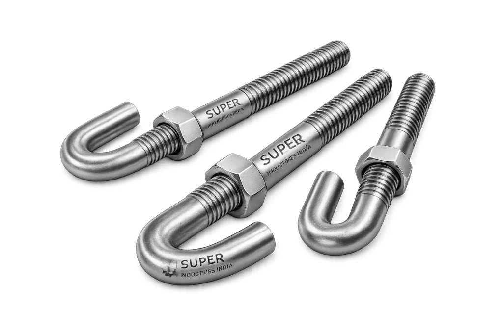
In modern structural engineering and infrastructure construction, the interface between steel and concrete is a critical design component. Structural steel columns, equipment base frames, transmission tower legs, bridge bearings, and industrial machine foundations all require reliable anchorage systems to resist operational loads.
J Bolts are widely used in cast-in-place anchoring systems where a hooked anchoring end provides mechanical resistance within the concrete mass.
Typical structural applications include:
• Structural steel column anchoring
• Power plant turbine foundations
• Oil and gas processing equipment foundations
• Petrochemical reactor structures
• Transmission tower base anchoring
• Bridge bearing assemblies
• Industrial machinery foundations
• Pre-engineered building (PEB) column bases
• Infrastructure construction foundations
In these applications, anchor bolts must resist:
• Vertical tensile forces
• Horizontal shear forces
• Overturning moments from structural loads
• Dynamic loads caused by vibration, wind, or seismic activity
J Bolts provide anchorage through mechanical hook engagement within concrete, making them suitable for foundation conditions where the anchoring load is primarily tensile or combined tension and shear.
Embedded Anchoring Systems in Concrete Foundations
Structural anchor bolts are generally categorized into several design configurations depending on the anchoring mechanism and installation method.
Common anchor bolt types used in structural construction include:
Straight Anchor Bolts
Straight anchor bolts are threaded rods embedded directly into concrete without a mechanical hook or bend. Their resistance against pull-out forces depends primarily on bond strength between the steel surface and the surrounding concrete.
These anchors are typically used in applications where embedment depth is sufficiently large to develop bond stress resistance.
L-Bolts (L-Shaped Anchor Bolts)
L-shaped anchor bolts contain a 90-degree bend at the embedded end. The horizontal leg of the bend provides mechanical resistance against pull-out forces. L-bolts are commonly used in structural column anchoring where moderate tensile loads are expected.
Stud Anchors
Stud anchors are headed fasteners with a forged or welded head at the embedded end. These are frequently used in composite steel–concrete systems or equipment anchoring systems where the head provides bearing resistance within concrete.
Chemical Anchors
Chemical anchors are post-installed systems where threaded rods are bonded into drilled holes using chemical adhesive systems such as epoxy or polyester resin. These anchors are commonly used for retrofit installations or where cast-in-place anchors cannot be installed.
However, chemical anchors require careful surface preparation and controlled installation procedures to achieve reliable load capacity.
Hooked Anchor Bolts (J Bolts)
J Bolts represent a hooked anchor bolt configuration in which the embedded end forms a curved hook resembling the letter “J”. This hook creates a mechanical interlock with the surrounding concrete, increasing resistance to tensile pull-out forces.
Compared with straight anchor rods relying on bond stress alone, hooked anchor bolts provide a more reliable mechanical anchorage mechanism.
Advantages of J Bolts include:
• Increased pull-out resistance
• Reliable mechanical anchorage in concrete
• Reduced dependence on bond strength
• Improved load transfer stability
• Suitable for medium to heavy structural loads
For these reasons, J Bolts are commonly specified in industrial structural foundations and heavy equipment anchoring systems.
Super Industries
Global Manufacturer of Heavy & Custom Engineered Fasteners & Flanges.
2. Technical Definition
A J Bolt is an embedded structural anchor fastener with a threaded upper section and a curved hook-shaped anchoring end designed for cast-in-place installation in concrete foundations.
The threaded end protrudes above the concrete surface and allows structural components—such as base plates, machinery frames, or steel columns—to be secured using nuts and washers.
The hook-shaped end is embedded in concrete and functions as a mechanical anchorage feature, preventing the bolt from being pulled out when tensile loads are applied.
Key Structural Components of a J Bolt
A standard J Bolt contains several functional sections:
Threaded Section
The upper section of the bolt is threaded to allow engagement with nuts and washers. This section remains exposed above the concrete surface after foundation casting.
Thread types typically follow standardized thread profiles such as:
• UNC (Unified National Coarse)
• UNF (Unified National Fine)
• Metric coarse thread
Thread engagement must be sufficient to ensure full tensile load transfer through the nut and washer assembly.
Shank Section
The shank is the straight portion of the bolt extending between the threaded section and the hook. This section transfers tensile load from the threaded portion to the anchoring hook.
The shank diameter directly influences tensile strength and shear capacity.
Hooked Anchorage End
The curved hook forms the anchoring element within the concrete. The hook radius and bend geometry influence the load distribution and anchorage performance.
The hook prevents the bolt from being extracted from concrete when subjected to tensile loading.
Structural Load Transfer Mechanism
In structural anchoring systems, J Bolts transfer loads from steel structures into concrete foundations through a defined load path:
Steel structure
→ Base plate
→ Anchor bolt threads
→ Bolt shank
→ Hook anchorage
→ Concrete foundation mass
This load transfer mechanism ensures structural stability and prevents uplift or sliding under service loads.
Structural Load Categories
Structural anchor bolts must resist different categories of loads depending on the application and structural design conditions.
Tensile Loads
Tensile loads act along the axis of the bolt and attempt to pull the bolt out of the concrete foundation. These loads are commonly generated by:
• Wind uplift forces
• Structural overturning moments
• Equipment vibration
• Seismic loading
J Bolts resist tensile forces primarily through the hook anchorage embedded within concrete.
Shear Loads
Shear loads act perpendicular to the bolt axis and attempt to slide the bolt relative to the surrounding concrete.
Shear forces may occur due to:
• Horizontal loads on structural frames
• Equipment operational forces
• Thermal expansion forces
• Lateral seismic loads
Shear resistance is provided by:
• Bolt shear strength
• Bearing resistance between bolt and concrete
• Friction between base plate and foundation
Combined Loading
In many industrial applications, anchor bolts experience combined tensile and shear loading simultaneously.
Examples include:
• Structural column base connections
• Bridge support anchors
• Heavy machinery foundations
• Transmission tower bases
Structural design must therefore consider interaction between tensile capacity and shear capacity.
3. Structural Anchoring Principle
The structural performance of J Bolts depends on the interaction between steel fasteners and the surrounding concrete mass. The anchorage behavior is governed by several structural mechanisms that collectively determine load resistance.
These mechanisms include:
• Mechanical hook anchorage
• Concrete bearing resistance
• Bond stress between steel and concrete
• Frictional resistance
Each mechanism contributes to the overall anchoring capacity.
Mechanical Hook Anchorage
The primary anchoring mechanism of J Bolts is the curved hook at the embedded end. When tensile force attempts to pull the bolt out of the concrete, the hook bears against the surrounding concrete mass.
This creates a mechanical interlock that resists extraction.
The effectiveness of hook anchorage depends on:
• Hook radius
• Embedment depth
• Concrete compressive strength
• Bolt diameter
A properly designed hook geometry ensures that the tensile load is distributed over a larger concrete volume, reducing the risk of localized failure.
Concrete Pull-Out Resistance
Concrete pull-out resistance refers to the ability of the surrounding concrete to resist forces attempting to extract the anchor bolt.
When tensile loads are applied, stresses develop around the hook region and propagate into the surrounding concrete.
If the applied load exceeds the concrete capacity, a failure cone may form around the anchor bolt.
This failure mode is known as concrete breakout failure.
Bearing Resistance of Concrete
When the hook of a J Bolt is loaded in tension, compressive stresses develop between the curved steel surface and the surrounding concrete.
Concrete bearing resistance helps distribute the load into the foundation mass.
Higher concrete compressive strength improves the anchoring capacity of the bolt.
Bond Stress Between Steel and Concrete
In addition to mechanical hook resistance, some portion of the load is transferred through bond stress between the steel bolt surface and the surrounding concrete.
Bond stress depends on:
• Surface roughness of the bolt
• Concrete compaction quality
• Presence of corrosion protection coatings
• Embedment length
Although bond stress contributes to anchorage, it is not the primary resistance mechanism for J Bolts.
Load Path Through Anchor Bolt Systems
In structural base plate connections, loads follow a defined path through the anchoring system.
Load transfer sequence:
Structural load from steel column
→ transmitted to base plate
→ transferred to anchor bolt threads through nut preload
→ transmitted through bolt shank
→ resisted by hook anchorage in concrete
→ distributed into foundation mass
Understanding this load path is essential for proper structural design and anchor bolt sizing.
Anchor Bolt Group Behavior
In structural applications, anchor bolts are typically installed in groups beneath structural base plates.
The load distribution among bolts depends on:
• Bolt spacing
• Base plate stiffness
• Structural load eccentricity
• Foundation rigidity
Anchor bolt groups must be designed to ensure that individual bolts are not overloaded under combined structural loading.
Failure Modes in Anchor Bolt Systems
Structural anchor bolts can fail through several mechanisms if design limits are exceeded.
Common failure modes include:
Concrete Breakout
Concrete surrounding the anchor bolt fractures and forms a cone-shaped failure surface.
This occurs when tensile load exceeds the tensile capacity of the surrounding concrete.
Steel Yielding
If the tensile force exceeds the yield strength of the bolt material, the steel bolt may undergo plastic deformation.
High-strength alloy bolts are typically selected to avoid this failure mode.
Pull-Out Failure
Pull-out failure occurs when the bolt is extracted from the concrete without significant concrete breakout. This can occur if the hook anchorage is insufficient or embedment depth is inadequate.
Shear Failure
Shear failure occurs when lateral loads exceed the shear strength of the bolt shank.
This type of failure may occur in structural base connections subjected to horizontal loads.
Influence of Embedment Depth
Embedment depth is one of the most critical parameters in anchor bolt design.
Greater embedment depth provides:
• Larger concrete engagement volume
• Higher pull-out resistance
• Improved structural reliability
However, embedment depth must be balanced with:
• Foundation thickness
• Reinforcement cage geometry
• Installation constraints
Structural design codes and engineering guidelines specify minimum embedment requirements based on bolt diameter and structural loads.
Super Industries
Global Manufacturer of Heavy & Custom Engineered Fasteners & Flanges
4. Applicable Standards (ASTM / DIN / ISO)
J Bolts used in structural anchoring systems are typically manufactured according to internationally recognized fastener and material standards. These standards define the mechanical properties, chemical composition, dimensional tolerances, testing requirements, and marking practices necessary to ensure structural reliability.
In industrial construction and infrastructure projects, anchor bolts are generally specified according to ASTM material standards, supplemented by DIN or ISO dimensional references.
ASTM Standards for Anchor Bolts
ASTM A307
ASTM A307 specifies carbon steel bolts and threaded fasteners intended for general-purpose structural use.
Key characteristics include:
• Carbon steel composition
• Moderate tensile strength
• Common usage in structural assemblies and foundation anchoring
ASTM A307 bolts are typically used in applications where loading conditions are moderate and where higher strength grades are not required.
ASTM A36
ASTM A36 is a structural carbon steel specification widely used for plates, shapes, and bars.
When used as raw material for anchor bolts, ASTM A36 provides:
• Good weldability
• Moderate yield strength
• Reliable structural performance in foundation anchoring applications
Although not a dedicated fastener specification, A36 material is commonly used for fabricated anchor bolts.
ASTM F1554 (Anchor Bolt Specification)
ASTM F1554 is the primary specification for anchor bolts used in structural steel foundations.
The standard defines three strength grades:
Grade 36
Grade 55
Grade 105
These grades correspond to increasing mechanical strength levels and are commonly specified in:
• Structural steel column bases
• Transmission towers
• Industrial equipment foundations
• Infrastructure projects
ASTM F1554 also defines:
• Thread requirements
• Bend test requirements
• Marking requirements for grade identification
ASTM A193 B7
ASTM A193 Grade B7 is an alloy steel fastener specification designed for high-strength applications and elevated temperature service.
Key characteristics:
• Chromium–molybdenum alloy steel
• Quenched and tempered heat treatment
• High tensile strength and hardness
B7 anchor bolts are often used in:
• Petrochemical plants
• Power generation facilities
• High-load machinery foundations
ISO and DIN References
DIN 529 – Anchor Bolts
DIN 529 provides dimensional guidance for anchor bolts used in structural foundations.
It defines configurations such as:
• Hooked anchor bolts
• L-shaped anchor bolts
• Straight anchor rods
Although many EPC projects rely primarily on ASTM specifications, DIN references are commonly used for dimensional geometry.
ISO Fastener Framework
ISO standards provide a global framework for thread forms, mechanical properties, and testing procedures.
Relevant ISO standards include:
• ISO 898 (mechanical properties of fasteners)
• ISO 965 (thread tolerances)
• ISO 3506 (stainless steel fasteners)
These standards support compatibility with international procurement specifications.
ASME Structural Fastening Principles
While ASME does not publish a dedicated J Bolt standard, structural fastening principles used in anchor bolt design align with ASME mechanical design practices.
Relevant engineering principles include:
• Load path analysis
• Stress calculations
• Material strength evaluation
• Factor-of-safety design methods
These engineering approaches are used during structural design verification and anchor bolt sizing calculations.
5. Material & Grade Options
Material selection for J Bolts depends on the structural load requirements, environmental exposure conditions, and service temperature range.
The most common materials fall into three categories:
• Carbon steel
• Alloy steel
• Stainless steel
Each category offers different mechanical strength and corrosion resistance characteristics.
Carbon Steel Anchor Bolts
Carbon steel is widely used for foundation anchoring due to its combination of structural strength, machinability, and cost efficiency.
Common carbon steel grades include:
ASTM A36
ASTM A307
ASTM F1554 Grade 36
ASTM F1554 Grade 55
These materials are typically used in:
• Industrial building foundations
• Structural steel column anchoring
• Infrastructure projects
• Transmission tower bases
Carbon steel anchor bolts are often protected using galvanizing or protective coatings when exposed to outdoor environments.
Alloy Steel Anchor Bolts
Alloy steel grades provide significantly higher strength compared with carbon steel.
Common alloy steel anchor bolt materials include:
ASTM A193 Grade B7
ASTM A320 Grade L7
These materials are typically used in:
• High-load structural applications
• Petrochemical facilities
• Power plants
• High-temperature equipment anchoring
Alloy steel bolts are usually heat treated through quenching and tempering to achieve the required mechanical properties.
Stainless Steel Anchor Bolts
Stainless steel materials are selected when corrosion resistance is a primary design requirement.
Common stainless steel grades include:
ASTM A193 B8 (Type 304 stainless steel)
ASTM A193 B8M (Type 316 stainless steel)
These materials are commonly used in:
• Marine environments
• Coastal infrastructure
• Chemical processing plants
• Water treatment facilities
Stainless steels offer high resistance to oxidation and chemical corrosion.
Mandatory Material Comparison Table
| Material Grade | Yield Strength (MPa) | Tensile Strength (MPa) | Temperature Range | Corrosion Resistance | Typical Industry Use |
|---|---|---|---|---|---|
| ASTM A36 | 250 | 400–550 | −20°C to 400°C | Low | Structural foundations |
| ASTM A307 | 250 | 400 | −20°C to 300°C | Low | General anchor bolts |
| ASTM F1554 Grade 36 | 250 | 400 | −20°C to 400°C | Low | Structural steel anchoring |
| ASTM F1554 Grade 55 | 380 | 520 | −20°C to 400°C | Moderate | Infrastructure construction |
| ASTM A193 B7 | 720 | 860 | −30°C to 540°C | Moderate | Petrochemical & power plants |
| ASTM A193 B8 | 205 | 515 | −200°C to 800°C | High | Marine and chemical plants |
| ASTM A193 B8M | 205 | 515 | −200°C to 800°C | Very High | Offshore and marine structures |
6. Heat Treatment Information
Heat treatment processes are used to modify the microstructure of steel and achieve the mechanical properties required for structural anchoring applications.
The heat treatment applied depends on the selected material grade.
Normalizing
Normalizing involves heating steel above its transformation temperature followed by controlled air cooling.
This process improves:
• Grain structure uniformity
• Mechanical strength consistency
• Dimensional stability
Normalizing is often used for carbon steel anchor bolts to achieve balanced mechanical properties.
Quenching and Tempering
Quenching and tempering is the most common heat treatment method for high-strength alloy bolts.
Process steps:
- Steel is heated to the austenitizing temperature.
- Rapid cooling (quenching) transforms the structure into martensite.
- Tempering is performed at a lower temperature to restore ductility.
Benefits include:
• High tensile strength
• Improved fatigue resistance
• Controlled hardness levels
ASTM A193 B7 bolts are typically produced using this heat treatment process.
Stress Relieving
Stress relieving is performed after forming or bending operations to reduce residual stresses.
This is particularly important for hooked anchor bolts, where bending introduces localized stresses.
Stress relieving improves:
• Dimensional stability
• Structural reliability
• Resistance to cracking
Solution Annealing (Stainless Steel)
Stainless steel anchor bolts are heat treated through solution annealing.
This process:
• Dissolves carbide precipitates
• Restores corrosion resistance
• Improves ductility
After solution annealing, the steel is rapidly cooled to prevent carbide formation.
Mechanical Property Impact
Heat treatment affects several key mechanical properties:
• Tensile strength
• Yield strength
• Hardness
• Ductility
• Impact resistance
These properties determine the structural performance of the anchor bolt under loading conditions.
Charpy Impact Testing
For structural applications subjected to dynamic loading or low temperatures, impact testing may be required.
Charpy impact tests measure the energy absorbed by the material during fracture.
This testing verifies:
• Material toughness
• Resistance to brittle fracture
• Structural reliability in cold environments
Impact testing is commonly required in:
• Oil and gas facilities
• Offshore platforms
• Low-temperature service environments
7. Manufacturing Process
The manufacturing of J Bolts requires controlled forming, threading, and inspection processes to ensure dimensional accuracy and mechanical integrity.
The process typically involves the following stages.
1. Raw Material Inspection
Steel bars are received with mill test certificates indicating:
• Chemical composition
• Mechanical properties
• Heat numbers
Incoming inspection verifies compliance with specified material standards.
2. Cutting and Bar Preparation
Bars are cut to the required length based on:
• Bolt diameter
• Hook bend allowance
• Thread length
• Overall bolt length
Cutting may be performed using band saws or automated bar cutting machines.
3. Hook Bending / Hot Forming
The characteristic J-shaped hook is formed through controlled bending.
Bending methods include:
• Cold bending for smaller diameters
• Hot forming for larger diameters
Controlled bend radius is essential to prevent material cracking or weakening.
4. Thread Rolling or Machining
Threads are produced using:
Thread rolling
or
Thread machining
Thread rolling is generally preferred because it improves fatigue resistance by compressing the grain structure of the steel.
Thread dimensions must comply with applicable thread standards.
5. Heat Treatment
If required by the material grade, bolts undergo heat treatment processes such as:
• Quenching and tempering
• Normalizing
• Stress relieving
Heat treatment parameters are controlled according to the specified material standard.
6. Surface Coating
Surface protection coatings are applied depending on environmental exposure conditions.
Common coatings include:
• Hot-dip galvanizing
• Zinc plating
• Epoxy coating
• PTFE coating
Surface preparation is critical for coating adhesion.
7. Dimensional Inspection
Dimensional inspection verifies compliance with design specifications.
Parameters checked include:
• Bolt diameter
• Thread length
• Hook radius
• Overall bolt length
• Straightness and alignment
8. Mechanical Testing
Mechanical testing confirms that the bolts meet the required strength levels.
Testing methods may include:
• Tensile testing
• Hardness testing
• Bend testing
9. Marking and Traceability
Anchor bolts are marked according to the applicable standard.
Typical marking information includes:
• Material grade
• Manufacturer identification
• Heat number traceability
Traceability ensures that each batch of bolts can be linked to its raw material source and test records.
8. J Bolt Dimension Table
The geometry of a J Bolt influences its installation behavior, anchoring performance, and load transfer capacity within a concrete foundation.
Key dimensional parameters include:
• Bolt diameter
• Thread pitch
• Hook radius
• Thread length
• Overall bolt length
• Embedment depth
The following reference table provides commonly used dimensional ranges for structural anchoring systems.
| Bolt Diameter | Thread Pitch | Hook Radius | Thread Length | Overall Length | Embedment Depth |
|---|---|---|---|---|---|
| M12 (½ in) | 1.75 mm | 20–25 mm | 40–60 mm | 200–300 mm | 120–180 mm |
| M16 (⅝ in) | 2.0 mm | 30–35 mm | 50–70 mm | 250–350 mm | 150–220 mm |
| M20 (¾ in) | 2.5 mm | 35–45 mm | 60–80 mm | 300–400 mm | 180–260 mm |
| M24 (1 in) | 3.0 mm | 45–55 mm | 70–100 mm | 350–500 mm | 220–320 mm |
| M30 (1-1/8 in) | 3.5 mm | 55–70 mm | 90–120 mm | 450–650 mm | 300–420 mm |
| M36 (1-1/2 in) | 4.0 mm | 70–90 mm | 100–140 mm | 600–800 mm | 420–550 mm |
Dimensional tolerances typically follow ISO thread tolerances and structural fabrication practices.
Important design considerations include:
• Sufficient embedment depth to develop concrete resistance
• Adequate thread engagement above the base plate
• Controlled bend radius to prevent stress concentration
Load Capacity Table
The load capacity of J Bolts depends on several parameters including:
• Bolt diameter
• Material grade
• Embedment depth
• Concrete compressive strength
• Installation spacing and edge distance
The following table presents typical design reference values for anchor bolts embedded in 30 MPa structural concrete.
| Bolt Size | Concrete Strength | Tensile Capacity | Shear Capacity | Safety Factor |
|---|---|---|---|---|
| M12 | 30 MPa | 12 kN | 8 kN | 3 |
| M16 | 30 MPa | 22 kN | 16 kN | 3 |
| M20 | 30 MPa | 35 kN | 25 kN | 3 |
| M24 | 30 MPa | 50 kN | 38 kN | 3 |
| M30 | 30 MPa | 75 kN | 55 kN | 3 |
| M36 | 30 MPa | 110 kN | 80 kN | 3 |
Actual load capacity must be verified using structural design calculations and project-specific engineering requirements.
Anchor bolt design must consider:
• Concrete breakout strength
• Steel tensile capacity
• Bond and pull-out resistance
• Interaction of shear and tension loads
Torque Chart for Anchor Bolt Installation
Proper torque application ensures that the nut and washer assembly securely clamps the structural base plate against the concrete foundation.
Torque values depend on:
• Bolt diameter
• Bolt grade
• Lubrication condition
• Thread friction coefficient
| Bolt Diameter | Class 8.8 Dry Torque | Class 8.8 Lubricated | Class 10.9 Dry Torque | ASTM B7 Torque |
|---|---|---|---|---|
| M12 | 85 Nm | 65 Nm | 120 Nm | 125 Nm |
| M16 | 210 Nm | 160 Nm | 300 Nm | 310 Nm |
| M20 | 420 Nm | 320 Nm | 600 Nm | 620 Nm |
| M24 | 720 Nm | 540 Nm | 1020 Nm | 1050 Nm |
| M30 | 1420 Nm | 1050 Nm | 2000 Nm | 2100 Nm |
| M36 | 2500 Nm | 1850 Nm | 3500 Nm | 3600 Nm |
Torque values may vary depending on:
• Washer type
• Surface finish
• Lubrication method
Field torque procedures should follow the structural installation specification of the project.
Anchor Bolt Load Calculation Guide
Structural engineers evaluate anchor bolts using established mechanical formulas.
The basic tensile stress relationship is:
![\[\sigma = \frac{F}{A}\]](https://superindustriesindia.in/wp-content/ql-cache/quicklatex.com-d820ba2a7649df33c4e35cab55485169_l3.png "Rendered by QuickLaTeX.com")
Where:
σ = tensile stress
F = applied force
A = cross-sectional area of the bolt
This relationship allows engineers to verify whether the applied tensile load exceeds the allowable stress of the bolt material.
Pull-Out Resistance Consideration
Pull-out resistance depends primarily on:
• Embedment depth
• Concrete strength
• Hook geometry
• Concrete breakout cone dimensions
Greater embedment depth increases the concrete volume engaged by the anchor and improves resistance to tensile extraction.
Example Structural Calculation
Consider an anchor bolt subjected to a tensile force of 50 kN.
Bolt diameter: M20
Cross-sectional tensile area (approximate): 245 mm²
The tensile stress in the bolt becomes:
50,000 N ÷ 245 mm² ≈ 204 MPa
If the selected material has a yield strength of 380 MPa, the stress level remains within acceptable limits under standard safety factors.
Structural design must also verify:
• Concrete breakout capacity
• Edge distance requirements
• Anchor group load distribution
Mechanical Property Table
Mechanical properties vary depending on the selected material grade and heat treatment condition.
| Material Grade | Yield Strength | Tensile Strength | Elongation | Hardness | Impact Value |
|---|---|---|---|---|---|
| ASTM F1554 Gr 36 | 250 MPa | 400 MPa | 23% | 120–170 HB | 27 J |
| ASTM F1554 Gr 55 | 380 MPa | 520 MPa | 20% | 150–200 HB | 27 J |
| ASTM A193 B7 | 720 MPa | 860 MPa | 16% | 248–321 HB | 40 J |
| ASTM A193 B8 | 205 MPa | 515 MPa | 30% | 150–200 HB | 60 J |
| ASTM A193 B8M | 205 MPa | 515 MPa | 30% | 150–200 HB | 60 J |
These properties influence the load-carrying capacity and structural reliability of anchor bolts used in industrial construction.
Corrosion Resistance Comparison Table
Environmental exposure conditions play a critical role in material selection for anchor bolts.
| Material Type | Marine Environment | Industrial Atmosphere | Chemical Exposure | Outdoor Infrastructure |
|---|---|---|---|---|
| Carbon Steel | Poor | Moderate | Poor | Moderate |
| Galvanized Steel | Moderate | Good | Moderate | Good |
| Stainless Steel 304 | Good | Very Good | Moderate | Very Good |
| Stainless Steel 316 | Excellent | Excellent | Very Good | Excellent |
Coating systems such as hot-dip galvanizing or epoxy coatings are frequently used to improve corrosion resistance of carbon steel anchor bolts.
9. Inspection & Quality Control Methods
Quality verification of J Bolts involves a combination of dimensional inspection, mechanical testing, and non-destructive evaluation.
Inspection procedures ensure compliance with material specifications and dimensional tolerances.
Positive Material Identification (PMI)
PMI testing verifies the alloy composition of the material using spectrometric analysis.
PMI is particularly important when supplying:
• Alloy steel anchor bolts
• Stainless steel bolts
• High-strength fasteners
Tensile Testing
Tensile testing determines:
• Yield strength
• Ultimate tensile strength
• Elongation characteristics
Samples are tested according to ASTM or ISO testing procedures.
Hardness Testing
Hardness tests verify heat treatment conditions and mechanical strength levels.
Common hardness testing methods include:
• Brinell hardness test
• Rockwell hardness test
Bend Testing
Bend tests are particularly relevant for anchor bolts with hooks or bends.
This test ensures that the bolt can withstand forming stresses without cracking.
Thread Gauge Inspection
Thread accuracy is verified using:
• Go / No-Go gauges
• Thread pitch gauges
This inspection ensures compatibility with standard nuts and washers.
Dimensional Inspection
Critical dimensional checks include:
• Bolt diameter
• Thread length
• Hook radius
• Overall length
• Straightness
Inspection tools may include calipers, micrometers, and coordinate measuring equipment.
Non-Destructive Testing (NDT)
When required for critical projects, additional inspection methods may be used.
Magnetic Particle Inspection (MPI)
Used to detect surface cracks in ferromagnetic materials.
Dye Penetrant Inspection (DPI)
Used to detect surface discontinuities in stainless steel or non-magnetic materials.
Third-Party Inspection
Large infrastructure and EPC projects frequently require independent inspection by accredited organizations.
Common third-party inspection agencies include:
• SGS
• Bureau Veritas (BV)
• TÜV
• DNV
Inspection scope may include:
• Material verification
• Mechanical testing review
• Dimensional checks
• Documentation audit
Certification Documentation
Anchor bolt shipments for international projects are typically supplied with inspection certification.
The most common certification standard is:
EN 10204
Two certification levels are widely used:
• EN 10204 3.1 – Manufacturer test certificate
• EN 10204 3.2 – Third-party witnessed certification
These documents confirm compliance with project specifications and material standards.
10. Industries Served
J Bolts are widely used across industries that rely on structural steel anchoring and heavy equipment foundation systems. In these sectors, anchor bolts are designed according to project-specific engineering requirements and must comply with applicable international material standards.
Oil & Gas Facilities
In oil and gas installations, structural anchoring systems are used to secure process equipment, pipe racks, compressor skids, and structural platforms.
Typical applications include:
• Refinery structural steel supports
• Pipe rack foundations
• Pump and compressor skid foundations
• Offshore module base frames
• Storage tank anchoring systems
In these environments, anchor bolts may be exposed to:
• Hydrocarbon vapors
• High temperatures
• Corrosive atmospheres
Material grades such as ASTM A193 B7 or stainless steel anchor bolts are often specified to meet structural and environmental requirements.
Petrochemical Plants
Petrochemical facilities require anchor bolts for the installation of heavy process equipment and structural support systems.
Common applications include:
• Reactor support structures
• Distillation column foundations
• Heat exchanger supports
• Process piping rack anchoring
• Equipment platforms
These installations often involve dynamic loads and thermal expansion, which must be considered in anchor bolt design.
Power Generation Facilities
Power plants rely extensively on foundation anchoring systems for turbines, generators, boilers, and structural steel frameworks.
Applications include:
• Steam turbine foundations
• Generator base frames
• Cooling tower structural anchoring
• Boiler support structures
• Pipe rack installations
These systems are designed to resist:
• Vibration loads
• Dynamic rotational forces
• Thermal expansion loads
Anchor bolt design must therefore consider fatigue resistance and structural load distribution.
Infrastructure Construction
Large infrastructure projects rely on anchor bolts to secure structural steel elements to concrete foundations.
Typical infrastructure applications include:
• Bridge bearing assemblies
• Highway gantry structures
• Lighting tower foundations
• Signage support structures
• Railway platform structures
Infrastructure anchor bolts are typically designed for long service life under outdoor environmental exposure.
Bridges
Bridge construction requires high-reliability anchoring systems for structural bearings, expansion joints, and steel supports.
J Bolts may be used in:
• Bridge pier bearing assemblies
• Structural steel anchor plates
• Guardrail support structures
• Bridge deck components
Structural engineers must verify that anchor bolts resist traffic loads, wind forces, and structural movement.
Railway Infrastructure
Railway construction projects frequently use anchor bolts to secure steel structures associated with track infrastructure and station facilities.
Applications include:
• Signal tower foundations
• Platform canopy structures
• Electrical equipment supports
• Overhead line support structures
These installations must maintain alignment and stability under dynamic loads generated by train movement.
Transmission Towers
Electrical transmission infrastructure uses anchor bolts to secure tower legs to reinforced concrete foundations.
Typical installations include:
• Lattice transmission towers
• Substation equipment structures
• Transformer support frames
Anchor bolts must resist wind loads and structural overturning forces.
Steel Plants and Heavy Industry
Steel plants and heavy manufacturing facilities contain large structural frames and heavy machinery foundations requiring high-capacity anchor bolts.
Applications include:
• Rolling mill foundations
• Furnace structural supports
• Crane rail anchoring systems
• Industrial platform structures
These installations may involve large-diameter anchor bolts with deep embedment depths.
Cement Plants
Cement manufacturing facilities rely on anchor bolts for the installation of rotating equipment and heavy process machinery.
Applications include:
• Rotary kiln foundations
• Crusher installations
• Conveyor support frames
• Structural steel process towers
In these environments, anchor bolts may be exposed to:
• Dust particles
• High temperatures
• Vibration loads
11. Export Capability & Global Supply
J Bolts used in industrial construction projects are frequently supplied as part of international EPC procurement packages.
Manufacturers supplying global projects must support documentation, traceability, packaging, and logistics requirements associated with large-scale infrastructure developments.
Regions Commonly Supplied
Industrial fasteners and anchor bolts are supplied to projects across multiple geographic regions.
Common project regions include:
• United States
• Europe
• Middle East
• Southeast Asia
Each region may apply different combinations of ASTM, ISO, or project-specific specifications.
Export Documentation
International supply of structural fasteners typically requires several documentation elements.
Common documentation includes:
• Material test certificates
• Mechanical test reports
• Dimensional inspection records
• Heat treatment reports
• Coating certification
• Packing lists and traceability documentation
These documents are reviewed by EPC procurement teams and project consultants prior to shipment acceptance.
Material Traceability
Material traceability ensures that each anchor bolt can be linked to its raw material origin and mechanical testing records.
Traceability elements include:
• Heat number identification
• Material certificates
• Manufacturing batch records
• Inspection reports
Traceability is particularly important for critical structural applications and regulated infrastructure projects.
Export Packaging Standards
Anchor bolts are typically packaged according to international shipping and handling requirements.
Packaging practices may include:
• Wooden crates
• Palletized bundles
• Protective wrapping
• Moisture-resistant packaging
Protective measures ensure that bolts arrive at the project site without corrosion damage or thread deformation.
Procurement & Installation Considerations
Anchor bolts are normally installed during the foundation construction phase, before the concrete is poured.
Proper positioning and alignment are critical to ensure compatibility with structural base plates.
Bolt Positioning in Foundations
J Bolts must be positioned accurately within the reinforcement cage according to the foundation design drawing.
Key considerations include:
• Bolt spacing
• Bolt orientation
• Projection height above concrete surface
• Alignment with base plate holes
Incorrect positioning can lead to installation difficulties or structural misalignment.
Template Installation Method
To ensure accurate placement, anchor bolts are commonly installed using steel templates or bolt setting plates.
Templates maintain correct:
• Bolt spacing
• Bolt alignment
• Bolt projection height
During concrete placement, the template prevents bolt movement and maintains the design position.
Concrete Pouring Considerations
During foundation casting, anchor bolts must remain stable and properly aligned.
Installation procedures typically include:
• Securing bolts to reinforcement bars
• Protecting exposed threads
• Monitoring bolt position during concrete placement
Vibration of concrete should not disturb bolt alignment.
Bolt Alignment Control
After concrete placement and curing, anchor bolt alignment must be verified before structural steel installation.
Inspection checks include:
• Bolt spacing verification
• Vertical alignment checks
• Projection height measurement
Minor alignment corrections may be performed using shim plates or slotted base plate holes, depending on structural design allowances.
Thread Protection During Casting
The exposed threaded section of anchor bolts must be protected during construction activities.
Protection methods include:
• Plastic thread caps
• Protective tape wrapping
• Grease coating
These measures prevent concrete contamination or thread damage.
Field Inspection Checkpoints
Before structural installation, field inspection typically verifies:
• Bolt diameter and thread condition
• Bolt projection height
• Bolt spacing accuracy
• Surface coating condition
Inspection ensures that anchor bolts meet the requirements of the structural design.
Re-Tightening Procedures
After structural steel components are installed, nuts are tightened to the specified torque level.
In some installations, re-tightening may be performed after initial structural settlement.
Torque verification ensures:
• Proper load transfer
• Structural stability
• Resistance to vibration-induced loosening
Storage and Handling Practices
Anchor bolts delivered to construction sites should be stored in controlled conditions to prevent damage or corrosion.
Recommended storage practices include:
• Keeping bolts above ground level
• Protecting threads from mechanical damage
• Avoiding exposure to standing water
• Maintaining original packaging until installation
Proper storage preserves the mechanical integrity and dimensional accuracy of the fasteners.
Custom Engineering Capabilities
Industrial construction projects frequently require custom anchor bolt configurations based on structural design requirements.
Custom manufacturing may include:
• Special hook geometry
• Extended embedment depth
• Large-diameter anchor bolts
• Long anchor bolts for deep foundations
• Project-specific coatings
• Custom thread lengths
• Project identification markings
Custom anchor bolts are typically manufactured based on engineering drawings or EPC project specifications.
Conclusion
J Bolts are an integral component of structural anchoring systems used in concrete foundations for industrial and infrastructure construction. Their hook-shaped anchoring design provides mechanical resistance against tensile pull-out forces while enabling reliable load transfer from steel structures into the surrounding concrete mass.
When properly designed, manufactured, and installed, J Bolts contribute to the structural stability of a wide range of installations including power plants, petrochemical facilities, transmission infrastructure, bridges, and heavy machinery foundations.
Engineering considerations such as material grade selection, embedment depth, bolt spacing, corrosion protection, and mechanical testing play a critical role in ensuring anchor bolt performance throughout the service life of the structure.
For EPC contractors, structural engineers, and project consultants, evaluation of anchor bolt suppliers typically focuses on material traceability, compliance with international standards, manufacturing discipline, and inspection documentation.
Anchor bolt systems must therefore be manufactured and supplied with full technical documentation and dimensional control to support structural design requirements and project verification procedures.