
STEP BOLTS
Super Industries “Global Manufacturer of Heavy & Custom Engineered Fasteners for Oil & Gas, Power & EPC Contractors.”
1. Industry Context & System Relevance
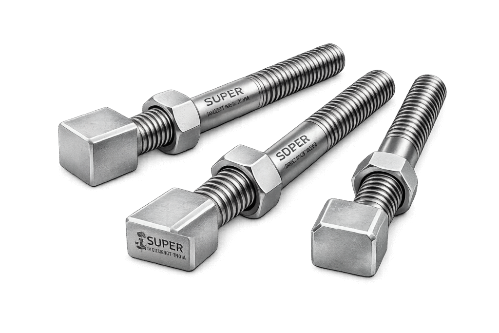
In heavy mechanical assemblies, fastening systems must perform far beyond basic component retention. Structural machinery, industrial equipment frames, and high-load mechanical interfaces require fasteners capable of controlling load transfer, component alignment, and shear resistance while maintaining dimensional stability under static and cyclic loading conditions.
Within such assemblies, STEP BOLTS are used where precise positioning and controlled load distribution are essential.
Unlike uniform-diameter bolts, stepped bolts incorporate multiple shank diameters designed to perform specific structural functions inside an assembly. The stepped geometry enables the bolt to serve simultaneously as:
- A load-transferring fastener
- A precision alignment element
- A controlled shear interface
- A wear-resistant positioning shaft
This dual role makes STEP BOLTS widely used in heavy equipment engineering, where the fastener becomes part of the structural load path.
Engineering Systems Where STEP BOLTS Are Commonly Applied
STEP BOLTS are widely implemented in:
1. Structural Mechanical Assemblies
Large equipment structures such as steel frames, drive housings, and industrial machine bodies require precise alignment between connected components. Stepped bolts ensure consistent positioning during assembly and operational loading.
2. Heavy Equipment Alignment Systems
Mining trucks, excavators, and drilling rigs rely on stepped bolts to maintain alignment between mechanical subassemblies such as:
- Gearbox housings
- Hydraulic mounting brackets
- Drive shaft supports
3. Mining Machinery
Mining equipment experiences:
- High shock loading
- Cyclic vibration
- Abrasive operating environments
STEP BOLTS are often used in bucket assemblies, crusher structures, and dragline components where both shear and positioning control are required.
4. Construction Equipment
Bulldozers, cranes, and material handling equipment frequently use stepped fasteners in:
- Structural articulation points
- Blade mounting structures
- Track frame assemblies
5. Turbine and Generator Housings
Power generation systems contain large rotating components that must maintain precise alignment tolerances. STEP BOLTS are used to secure housings while maintaining positional accuracy between mating components.
6. Rail and Infrastructure Assemblies
Rail infrastructure requires mechanical connections that resist:
- cyclic load fatigue
- vibration from rolling stock
- thermal expansion
STEP BOLTS are often used in rail fastening systems and track support structures.
7. Precision Machine Structures
High-precision machine tools rely on stepped fasteners to control:
- machine frame alignment
- structural rigidity
- component positioning accuracy
Why Stepped Shank Bolts Are Used Instead of Uniform Diameter Bolts
In standard fasteners, the shank diameter is constant along the bolt length. While suitable for general fastening, uniform bolts have limitations in assemblies where shear loading and alignment requirements are significant.
STEP BOLTS solve these limitations through geometric load control.
1. Load Distribution
A stepped shank allows engineers to control where loads are transferred within the assembly. Larger diameters carry structural loads, while smaller threaded sections provide clamping force.
This reduces stress concentration in critical areas.
2. Controlled Shear Transfer
The shoulder section of a STEP BOLT is typically positioned at the shear plane between connected components. This allows shear forces to act on a precision-machined cylindrical surface rather than on threads.
Benefits include:
- Improved shear strength
- Reduced thread deformation
- Increased fatigue life
3. Component Alignment
The shoulder diameter often fits into precision-machined holes in the mating components. This creates an alignment feature similar to a dowel pin while maintaining the benefits of a bolted connection.
4. Wear Resistance
Because the stepped shoulder acts as a bearing surface, wear occurs on the solid cylindrical shank rather than the threaded section.
This improves durability in moving or vibration-prone assemblies.
5. Precision Positioning
In assemblies requiring consistent geometry — such as heavy equipment joints — stepped bolts control component positioning with greater accuracy than standard bolts.
Super Industries
Global Manufacturer of Heavy & Custom Engineered Fasteners & Flanges
2. Technical Definition of STEP BOLTS
A STEP BOLT is a mechanical fastener designed with two or more distinct shank diameters along its axis, forming stepped transitions that provide functional load zones within an assembly.
These stepped diameters serve specific engineering purposes, including:
- Controlled shear zones
- Alignment guidance
- Variable stress distribution
- Mechanical positioning
- Structural load transfer
Unlike conventional bolts where the threaded portion and shank share the same diameter, STEP BOLTS separate these functions into distinct geometric sections.
Key Structural Features of STEP BOLTS
1. Head Configuration
The bolt head provides the interface for torque application and load distribution.
Common head types include:
- Hexagonal heads
- Heavy hex heads
- Socket heads
- Custom flange heads
The head geometry must support the required torque transmission without deformation.
2. Step Diameter Transitions
The defining characteristic of STEP BOLTS is the change in diameter along the bolt shank.
Each step transition serves a mechanical purpose.
Typical step functions include:
- Load-bearing shoulders
- Precision alignment diameters
- Reduced thread diameter zones
- Bearing surfaces for rotating components
Step transitions are designed with fillet radii to reduce stress concentration.
3. Threaded Section
The threaded section provides clamping force within the assembly.
Thread design considerations include:
- thread class
- pitch selection
- engagement length
- preload capability
Threaded sections typically follow international standards such as:
- ISO metric threads
- Unified thread series (UNC / UNF)
4. Shoulder Section
The shoulder section is a precision-machined cylindrical area that typically serves as:
- shear load carrier
- alignment feature
- bearing surface
In many assemblies, the shoulder fits into a close tolerance hole.
This prevents lateral movement between components.
5. Bearing Surface
The interface between the bolt head and the clamped surface must maintain adequate contact area to prevent local deformation.
Bearing surfaces are typically:
- machined flat
- perpendicular to the bolt axis
- designed to distribute clamping force evenly
Types of STEP BOLTS
Single Step Bolts
Single step bolts contain one diameter transition between the shoulder and the threaded section.
Typical uses include:
- structural machinery mounting
- gearbox housing assemblies
- equipment frame connections
Double Step Bolts
Double step bolts incorporate two diameter transitions along the shank.
This configuration is used where:
- multiple shear planes exist
- alignment must be maintained across several components
- staged load transfer is required
Custom Stepped Fasteners
Many heavy equipment manufacturers require project-specific stepped bolt designs.
Custom stepped fasteners may include:
- extended shoulder lengths
- multiple precision diameters
- special thread forms
- non-standard head geometries
These designs are developed according to equipment OEM specifications.
3. Engineering Load Principle
STEP BOLTS function as combined fastening and structural alignment elements.
Their stepped geometry directly influences how loads are transferred within the assembly.
Understanding these load mechanisms is essential for proper design and selection.
Tensile Load Transfer
Tensile loading occurs when the bolt is subjected to axial force along its length.
This is generated when the bolt is tightened to create preload within the assembly.
The preload clamps components together and allows friction between surfaces to resist external forces.
Tensile stress in the bolt is determined by the relationship between applied force and cross-sectional area.
Shear Load Handling
In many mechanical assemblies, bolts are exposed to transverse forces that attempt to slide components relative to each other.
STEP BOLTS handle shear loads through the shoulder diameter, which acts as the shear interface.
Advantages include:
- shear loads act on the solid cylindrical shank
- threads are protected from shear deformation
- improved fatigue resistance
Shoulder Load Support
The shoulder section carries loads through bearing contact with the assembly hole.
This provides:
- mechanical stability
- reduced lateral movement
- improved alignment retention
In many designs, the shoulder diameter is manufactured to close tolerance fits.
Bearing Stress on Stepped Diameters
When a stepped bolt is installed, the shoulder experiences bearing stress against the surrounding material.
This stress must remain within acceptable limits to avoid:
- hole deformation
- bolt bending
- component damage
Engineers evaluate bearing stress using material strength data and hole geometry.
Alignment Guidance via Shoulder Fit
The shoulder diameter acts similarly to a locating dowel.
When inserted into a precision-machined hole, the shoulder:
- prevents lateral displacement
- maintains component alignment
- improves structural stiffness
This is particularly important in:
- gearbox mounting
- turbine housings
- machine frames
Shear Plane Location
In mechanical design, the shear plane is the interface between two connected components.
Ideally, this shear plane should intersect the smooth shoulder diameter, not the threaded section.
This design approach prevents shear loading on threads.
Thread vs Shank Load Distribution
Threads are optimized for tensile loading, while the shank is better suited for shear loading.
STEP BOLTS intentionally separate these functions.
The threaded section produces clamping force, while the stepped shoulder absorbs shear forces.
Stress Concentration Control
Diameter transitions within a bolt can create stress concentration if not properly designed.
To prevent this, step transitions include fillet radii.
These radii distribute stress more evenly and improve fatigue life.
Bolt Preload Interaction with Stepped Geometry
Bolt preload plays a critical role in the performance of STEP BOLTS.
When correctly applied:
- the clamped components resist movement through friction
- shear forces are minimized
- fatigue loading on the bolt is reduced
4. Applicable International Standards Governing STEP BOLTS
STEP BOLTS used in structural and heavy mechanical assemblies must comply with internationally recognized fastener standards to ensure material consistency, mechanical performance, dimensional accuracy, and traceability.
Although stepped bolts are often custom-engineered components, their material properties, heat treatment requirements, and inspection procedures are governed by established standards from organizations such as ASTM, ISO, DIN, ASME, and EN.
Compliance with these standards ensures the fasteners are suitable for EPC project specifications, OEM equipment requirements, and third-party inspection procedures.
ASTM Fastener Material Standards
ASTM standards primarily govern material chemistry, mechanical properties, and heat treatment requirements for high-strength industrial fasteners.
For STEP BOLTS used in heavy equipment and structural machinery, ASTM standards are commonly used to specify:
- minimum yield strength
- ultimate tensile strength
- hardness limits
- impact resistance
- heat treatment conditions
Examples of relevant ASTM material standards include:
| ASTM Standard | Material Category | Application Context |
|---|---|---|
| ASTM A307 | Carbon steel fasteners | General structural bolting |
| ASTM A325 | High-strength structural bolts | Infrastructure and heavy equipment |
| ASTM A490 | Alloy steel structural bolts | High-load structural assemblies |
| ASTM A193 B7 | Chromium-molybdenum alloy steel | High-pressure and high-temperature applications |
| ASTM A193 B16 | High-temperature alloy steel | Power plant equipment |
| ASTM A193 B8 / B8M | Stainless steel fasteners | Corrosion-resistant assemblies |
These standards define mechanical property limits and ensure fasteners meet project engineering specifications.
DIN Bolt Standards
DIN standards historically defined dimensional requirements for European industrial fasteners. Many stepped fasteners still reference DIN geometry for:
- head dimensions
- thread forms
- bolt tolerances
- mechanical property classes
DIN standards commonly referenced during STEP BOLT manufacturing include:
| DIN Standard | Description |
|---|---|
| DIN 931 | Hex bolts with partial thread |
| DIN 933 | Fully threaded hex bolts |
| DIN 912 | Socket head cap screws |
| DIN 6914 | High-strength structural bolts |
Although stepped bolts often require custom machining, these standards establish baseline dimensional references.
ISO Mechanical Property Standards
ISO standards define mechanical property classes for metric fasteners.
One of the most important standards is:
ISO 898-1 — Mechanical Properties of Fasteners Made of Carbon Steel and Alloy Steel
This standard defines:
- tensile strength classes
- yield strength ratios
- elongation limits
- hardness ranges
Common strength classes include:
| Property Class | Minimum Tensile Strength |
|---|---|
| 8.8 | 800 MPa |
| 10.9 | 1000 MPa |
| 12.9 | 1200 MPa |
STEP BOLTS designed for heavy equipment often utilize Class 10.9 or Class 12.9 material properties.
ASME Mechanical Fastening Guidelines
ASME codes provide guidance for the application of fasteners in mechanical and pressure systems.
Relevant ASME references include:
- ASME B18.2.1 – Square and Hex Bolts
- ASME B1.1 – Unified Thread Standard
- ASME PCC-1 – Pressure Boundary Bolted Flange Joint Assembly
These standards influence:
- thread geometry
- bolt strength selection
- torque and preload requirements
- installation procedures
EN Fastener Standards
European Norm (EN) standards regulate fastener materials and mechanical performance for European industrial projects.
Examples include:
| EN Standard | Application |
|---|---|
| EN 14399 | High-strength structural bolting assemblies |
| EN 10204 | Inspection documentation |
| EN ISO 3506 | Stainless steel fastener properties |
EN standards are frequently required for EU infrastructure and industrial projects.
Influence of Standards on STEP BOLT Manufacturing
International standards influence multiple aspects of STEP BOLT production.
Strength Class Selection
Standards specify minimum yield and tensile strength values, ensuring the bolt can carry specified loads.
Dimensional Control
Head sizes, thread geometry, and tolerance classes are controlled by standardization systems.
Traceability Requirements
Project documentation requires traceability through:
- heat numbers
- material test certificates
- batch identification
Compliance with EPC Project Specifications
Engineering procurement contractors often specify standards directly in tender documents. Compliance with these standards ensures fasteners are suitable for global infrastructure and energy projects.
5. Material & Grade Options for STEP BOLTS
The selection of material for STEP BOLTS is determined by:
- required load capacity
- operating temperature
- environmental exposure
- fatigue resistance requirements
- corrosion resistance
Materials typically fall into three categories:
- carbon steel
- alloy steel
- stainless steel and corrosion-resistant alloys
Carbon Steel Grades
Carbon steels are widely used in structural bolting applications due to their cost efficiency and adequate mechanical strength.
ASTM A307
A general-purpose carbon steel fastener grade used for moderate structural loads.
Typical applications include:
- structural frames
- equipment mounting
- non-critical machinery components
ASTM A325
High-strength structural bolts used in infrastructure assemblies.
Applications include:
- bridge construction
- structural steel frames
- heavy equipment assemblies
ASTM A490
A high-strength alloy steel structural fastener designed for high-load connections.
These bolts provide higher tensile strength compared to A325.
Applications include:
- heavy structural assemblies
- load-bearing equipment frames
- industrial machinery structures
Alloy Steel Grades
Alloy steels provide improved strength and temperature resistance compared to carbon steels.
ASTM A193 B7
Chromium-molybdenum alloy steel commonly used in high-pressure and high-temperature environments.
Typical uses include:
- pressure vessels
- pipeline flanges
- power generation equipment
ASTM A193 B16
An alloy steel grade designed for higher temperature service.
Applications include:
- steam systems
- turbine assemblies
- power plant mechanical equipment
Stainless Steel Grades
Stainless steel fasteners are used where corrosion resistance is critical.
ASTM A193 B8
An austenitic stainless steel fastener commonly used in chemical and marine environments.
Advantages include:
- corrosion resistance
- good ductility
- resistance to oxidation
ASTM A193 B8M
A molybdenum-alloyed stainless steel grade providing improved resistance to:
- chloride corrosion
- marine environments
- chemical exposure
Duplex & Super Duplex Stainless Steel
Duplex stainless steels combine:
- high mechanical strength
- strong corrosion resistance
These materials are used in:
- offshore platforms
- subsea equipment
- desalination plants
MATERIAL COMPARISON TABLE
| Grade | Yield Strength | Tensile Strength | Temperature Range | Corrosion Resistance | Typical Industry Use |
|---|---|---|---|---|---|
| ASTM A307 | ~250 MPa | ~400 MPa | -20°C to 200°C | Low | Structural assemblies |
| ASTM A325 | ~660 MPa | ~830 MPa | -40°C to 300°C | Moderate | Bridges and heavy equipment |
| ASTM A490 | ~940 MPa | ~1040 MPa | -40°C to 400°C | Moderate | High-load structural connections |
| ASTM A193 B7 | ~720 MPa | ~860 MPa | -40°C to 450°C | Moderate | Oil & gas equipment |
| ASTM A193 B16 | ~760 MPa | ~965 MPa | up to 520°C | Moderate | High-temperature power systems |
| ASTM A193 B8 | ~205 MPa | ~515 MPa | -196°C to 400°C | High | Chemical plants |
| ASTM A193 B8M | ~205 MPa | ~515 MPa | -196°C to 400°C | High | Marine equipment |
6. Heat Treatment of STEP BOLTS
Heat treatment plays a critical role in developing the mechanical strength, hardness, and fatigue resistance required for heavy-duty stepped fasteners.
Heat treatment processes vary depending on the selected material.
Normalizing
Normalizing is used for carbon steels to refine the grain structure.
The process involves:
- Heating the material above its critical transformation temperature
- Allowing controlled air cooling
Benefits include:
- improved uniformity
- enhanced machinability
- reduced internal stresses
Quenching and Tempering
High-strength alloy steel STEP BOLTS often undergo quenching and tempering.
Quenching
The material is heated to the austenitizing temperature and rapidly cooled in oil or water.
This produces a hardened microstructure.
Tempering
The hardened material is reheated to a lower temperature to reduce brittleness while maintaining strength.
The result is a balance between:
- strength
- ductility
- fatigue resistance
Stress Relieving
Stress relieving removes residual stresses generated during machining or forging.
This process reduces the risk of:
- distortion
- fatigue cracking
- dimensional instability
Solution Annealing (For Stainless Steel)
Austenitic stainless steels are heat treated using solution annealing.
The process involves:
- Heating to approximately 1050°C
- Rapid cooling
This restores corrosion resistance and dissolves precipitated carbides.
Hardness Ranges
Typical hardness values for fasteners depend on strength class.
Examples:
| Grade | Typical Hardness Range |
|---|---|
| ASTM A325 | 24–34 HRC |
| ASTM A490 | 33–39 HRC |
| ASTM A193 B7 | 28–35 HRC |
Hardness testing confirms proper heat treatment.
Charpy Impact Testing
For critical structural applications, impact toughness is evaluated using Charpy V-notch testing.
This test measures the material’s ability to absorb energy during sudden loading.
It is particularly important in:
- cold environments
- structural assemblies exposed to shock loads
7. Manufacturing Process of STEP BOLTS
Manufacturing stepped bolts requires precise dimensional control because the bolt geometry directly influences load distribution within the assembly.
Production typically follows a multi-stage process.
1. Raw Material Inspection
Incoming material is verified for:
- chemical composition
- heat number traceability
- dimensional conformity
Material test certificates confirm compliance with the specified standard.
2. Forging or Bar Machining
Depending on the bolt size and production volume, the bolt blank is produced by:
- hot forging
- precision bar machining
Forging improves grain flow and mechanical strength.
3. CNC Turning of Stepped Profile
Computer-controlled lathes machine the stepped diameters.
This stage produces:
- primary shoulder diameter
- secondary alignment diameters
- transition radii between steps
Precision machining ensures dimensional accuracy.
4. Shoulder Machining
The shoulder surface is finished to achieve required tolerance and surface finish.
This area must maintain:
- precise diameter
- concentricity with the bolt axis
- smooth bearing surface
5. Thread Rolling or Thread Cutting
Threads are formed using either:
Thread rolling
- cold forming process
- improved fatigue strength
- smooth thread surface
Thread cutting
- used for large diameters
- suitable for hardened materials
6. Heat Treatment
After machining, bolts undergo heat treatment to achieve the specified mechanical properties.
Heat treatment cycles are controlled according to material specifications.
7. Surface Finishing
Protective coatings are applied depending on service conditions.
Common finishing methods include galvanizing, phosphate coating, and passivation.
8. Marking and Traceability
Each production batch is marked to allow traceability.
Marking typically includes:
- manufacturer identification
- material grade
- batch number
Traceability ensures compliance with project documentation requirements.
9. Final Inspection
Before release, bolts undergo inspection procedures to verify:
- dimensional accuracy
- mechanical properties
- surface condition
8. Dimensional & Design Logic for STEP BOLTS
The geometry of STEP BOLTS is determined by the functional requirements of the mechanical assembly. Each dimensional feature directly influences load transfer behavior, alignment accuracy, and fatigue resistance.
Unlike conventional bolts where the shank diameter remains constant, stepped bolts incorporate multiple diameters along the bolt axis to control structural load paths.
Engineering design for STEP BOLTS focuses on the following critical dimensional parameters.
Head Diameter
The bolt head must provide sufficient bearing surface to distribute clamping force across the mating component.
Design considerations include:
- bearing pressure limits
- torque transmission capability
- compatibility with standard tools
Typical head configurations include:
- heavy hex heads
- hex heads
- socket heads
- flange heads
The head diameter is usually designed according to ASME B18 or DIN dimensional references.
Step Diameter Ratio
The relationship between the shoulder diameter and the threaded section determines the load distribution along the bolt.
Typical ratios include:
| Shoulder Diameter | Thread Diameter |
|---|---|
| 1.1 – 1.3 × thread diameter | Standard alignment step |
| 1.3 – 1.5 × thread diameter | High shear capacity |
| >1.5 × thread diameter | Structural positioning applications |
The larger diameter provides a shear-resistant cylindrical surface that absorbs transverse forces within the assembly.
Shoulder Length
Shoulder length is designed to match the thickness of the components being aligned.
Engineering considerations include:
- shear plane location
- alignment engagement depth
- tolerance control
- load transfer distance
The shoulder must fully pass through the shear interface to ensure the load is carried by the solid cylindrical section rather than by threads.
Thread Length
Thread length must allow sufficient engagement with the mating nut or threaded component.
Typical design rules include:
- engagement length ≥ 1 × bolt diameter for steel
- engagement length ≥ 1.5 × diameter for softer materials
Thread length must also accommodate:
- washers
- locking systems
- thermal expansion allowance
Transition Radius
Step transitions must incorporate a fillet radius to prevent stress concentration.
Sharp transitions create localized stress peaks that reduce fatigue life.
Engineering practice typically uses:
- radius = 0.02–0.06 × bolt diameter
This radius distributes stress more evenly across the transition region.
Surface Finish Requirements
Surface finish affects fatigue resistance and wear performance.
Typical surface roughness targets:
| Surface Type | Typical Roughness |
|---|---|
| Shoulder bearing surface | Ra 0.8 – 1.6 µm |
| Thread surface | Ra 3.2 – 6.3 µm |
| Bolt head bearing face | Ra 1.6 – 3.2 µm |
Improved surface finish reduces crack initiation risk under cyclic loading.
Concentricity Control
Concentricity between the stepped diameters and threaded axis is essential.
Misalignment can produce:
- uneven load distribution
- bolt bending
- premature fatigue failure
Typical concentricity tolerance:
≤ 0.03 mm for precision assemblies
Runout Tolerance
Runout defines how accurately the bolt axis aligns with its rotational center.
Excessive runout may cause:
- installation difficulties
- uneven load transfer
Typical runout limits:
0.02–0.05 mm depending on bolt size
Shoulder Perpendicularity
The shoulder face must remain perpendicular to the bolt axis to ensure correct load transfer.
Typical tolerance:
≤ 0.05 mm per 25 mm diameter
Fit Tolerances for Alignment
STEP BOLTS often act as alignment features inside machined holes.
Typical tolerance classes include:
| Fit Type | Application |
|---|---|
| H7 / g6 | Precision alignment |
| H8 / f7 | General machinery |
| H9 / e8 | Heavy equipment assemblies |
These tolerance combinations ensure accurate positioning while allowing assembly clearance.
A. STEP BOLT DIMENSION TABLE (Typical Engineering Reference)
| Bolt Size | Step Diameter | Shoulder Length | Thread Length | Head Size |
|---|---|---|---|---|
| M16 | 18 mm | 40 mm | 30 mm | 24 mm |
| M20 | 24 mm | 50 mm | 35 mm | 30 mm |
| M24 | 28 mm | 60 mm | 40 mm | 36 mm |
| M30 | 34 mm | 75 mm | 45 mm | 46 mm |
| M36 | 42 mm | 90 mm | 55 mm | 55 mm |
These dimensions represent typical proportions used in heavy equipment fastening systems. Actual dimensions are determined by equipment design drawings and load calculations.
9. Load Capacity & Structural Engineering Behavior
STEP BOLTS must withstand combined loading conditions including:
- tensile loads
- shear loads
- cyclic fatigue stresses
- vibration-induced forces
Understanding load capacity is essential for correct bolt selection.
Tensile Load Capacity
Tensile capacity represents the maximum axial load the bolt can withstand before yielding or fracture.
It depends on:
- bolt diameter
- material grade
- heat treatment condition
- thread stress area
Shear Load Capacity
Shear capacity refers to the bolt’s ability to resist transverse forces applied across the shear plane.
For stepped bolts, shear loads act on the shoulder diameter, which provides higher resistance compared to threaded sections.
Fatigue Resistance
Bolts subjected to cyclic loading may experience fatigue failure over time.
STEP BOLTS improve fatigue resistance because:
- shear loads are transferred through the smooth shank
- stress concentrations in threads are minimized
Impact Load Tolerance
Heavy machinery often produces sudden shock loads.
Bolts must possess sufficient impact toughness to avoid brittle fracture.
Materials with higher Charpy impact energy values are preferred in such applications.
Vibration Resistance
Vibration can reduce bolt preload over time.
STEP BOLTS maintain alignment even if slight preload loss occurs, because the shoulder diameter continues to provide mechanical positioning within the joint.
B. LOAD CAPACITY TABLE (Typical Reference)
| Bolt Size | Tensile Capacity (kN) | Shear Capacity (kN) | Recommended Safety Factor |
|---|---|---|---|
| M16 | 157 | 94 | 2.0 |
| M20 | 245 | 147 | 2.0 |
| M24 | 353 | 212 | 2.0 |
| M30 | 561 | 337 | 2.0 |
| M36 | 817 | 490 | 2.0 |
Values vary depending on material grade and heat treatment.
C. TORQUE CHART FOR STEP BOLTS
Correct torque application ensures proper bolt preload.
Insufficient torque results in inadequate clamping force, while excessive torque may cause bolt yielding.
| Bolt Size | Strength Class | Recommended Torque (Nm) | Lubricated Torque (Nm) | Dry Torque (Nm) |
|---|---|---|---|---|
| M16 | 10.9 | 210 | 180 | 210 |
| M20 | 10.9 | 410 | 360 | 410 |
| M24 | 10.9 | 710 | 630 | 710 |
| M30 | 10.9 | 1420 | 1260 | 1420 |
| M36 | 10.9 | 2450 | 2170 | 2450 |
Torque values depend on:
- lubrication condition
- thread friction coefficient
- bolt strength class
D. PRELOAD CALCULATION GUIDE
Preload represents the tensile force generated when a bolt is tightened.
This force clamps components together and allows friction between surfaces to resist external loads.
Bolt Stress Relationship
The stress in a bolt is determined by the applied force and the cross-sectional area.
![\[\sigma = \frac{F}{A}\]](https://superindustriesindia.in/wp-content/ql-cache/quicklatex.com-d820ba2a7649df33c4e35cab55485169_l3.png "Rendered by QuickLaTeX.com")
Where:
- σ = bolt stress
- F = applied force
- A = stress area of the bolt
Torque–Preload Relationship
The relationship between torque and bolt preload can be expressed as:
![\[T = K F D\]](https://superindustriesindia.in/wp-content/ql-cache/quicklatex.com-ca2503eb941c5b3d5ae13b22c01ff9cb_l3.png "Rendered by QuickLaTeX.com")
Where:
- T = tightening torque
- K = torque coefficient (nut factor)
- F = preload force
- D = bolt diameter
Typical values of K range between 0.18 and 0.25, depending on lubrication.
Preload Design Guidelines
Engineering practice typically applies preload between:
60–75% of bolt yield strength
This ensures:
- sufficient clamping force
- avoidance of bolt yielding
- improved fatigue performance
Sample Preload Calculation
Example for M24 Class 10.9 STEP BOLT
Given:
- Diameter = 24 mm
- Torque coefficient (K) = 0.2
- Applied torque = 710 Nm
Using the torque equation:
![\[F = \frac{T}{K \times D}\]](https://superindustriesindia.in/wp-content/ql-cache/quicklatex.com-51b3cadc2e083d1fe6dac1928ff53032_l3.png "Rendered by QuickLaTeX.com")
Substituting values:
F ≈ 148 kN preload force
This preload maintains sufficient clamping force for heavy machinery connections.
Safety Factor Considerations
Safety factors account for uncertainties including:
- material variability
- installation errors
- load fluctuations
- environmental effects
Typical safety factors:
| Application | Safety Factor |
|---|---|
| Static machinery | 1.5 – 2.0 |
| Heavy equipment | 2.0 – 2.5 |
| Dynamic systems | 2.5 – 3.0 |
E. MECHANICAL PROPERTY TABLE
| Property | Typical Value (Class 10.9) |
|---|---|
| Yield Strength | 940 MPa |
| Tensile Strength | 1040 MPa |
| Hardness | 32–39 HRC |
| Elongation | ≥ 9% |
| Charpy Impact Energy | ≥ 27 J |
Mechanical properties must be verified through material testing and heat treatment certification.
10. Inspection & Quality Control Methods for STEP BOLTS
STEP BOLTS used in EPC and heavy equipment applications must undergo rigorous inspection procedures to verify:
- material integrity
- dimensional accuracy
- mechanical properties
Inspection programs follow international quality assurance standards.
Positive Material Identification (PMI)
PMI testing verifies the chemical composition of the material.
Methods include:
- X-ray fluorescence (XRF)
- optical emission spectroscopy (OES)
This confirms the material matches the specified alloy grade.
Ultrasonic Testing (UT)
Ultrasonic testing detects internal material defects such as:
- voids
- inclusions
- internal cracks
UT is particularly useful for large diameter fasteners.
Magnetic Particle Inspection (MPI)
MPI detects surface and near-surface cracks in ferromagnetic materials.
The bolt is magnetized and iron particles reveal defects through magnetic flux leakage.
Dye Penetrant Inspection (DPI)
Dye penetrant testing is used for detecting surface cracks in non-magnetic materials such as stainless steel.
Dimensional Inspection
Dimensional verification ensures compliance with engineering drawings.
Inspection methods include:
- coordinate measuring machines (CMM)
- micrometers and calipers
- thread gauges
Critical dimensions include:
- step diameters
- shoulder length
- thread pitch
- head dimensions
Hardness Testing
Hardness testing confirms proper heat treatment.
Common methods:
- Rockwell hardness testing
- Brinell hardness testing
Hardness values must fall within the specified range for the material grade.
Third-Party Inspection (TPI)
For EPC projects, inspection is often performed by independent agencies such as:
- project consultants
- inspection companies
- certification bodies
These inspections verify compliance with project specifications.
EN 10204 Inspection Documentation
Fasteners supplied to industrial projects often require inspection certificates according to EN 10204.
Typical documentation includes:
| Certificate Type | Description |
|---|---|
| 2.1 | Manufacturer declaration |
| 2.2 | Test report |
| 3.1 | Certified inspection document |
| 3.2 | Third-party verified certification |