
CASTEL NUTS
Super Industries
“Global Manufacturer of Heavy & Custom Engineered Fasteners for Oil & Gas, Power & EPC Contractors.”
1. Industry Context & System Relevance
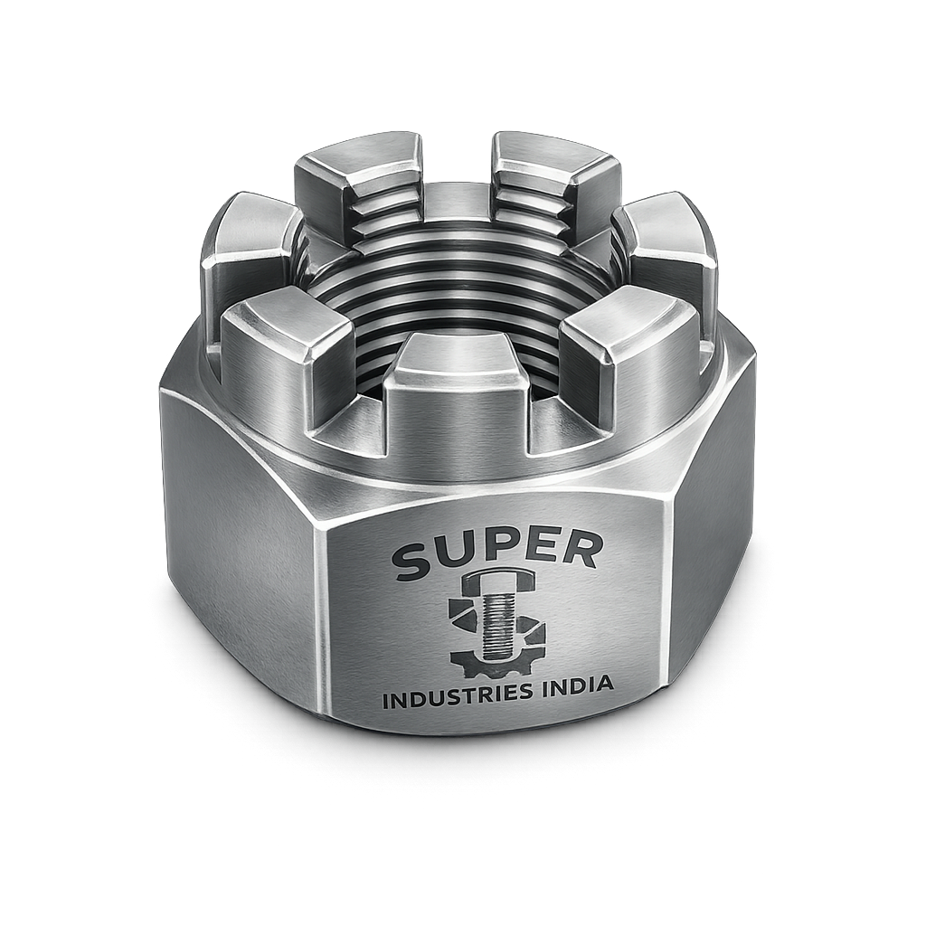
Role of Castellated Nuts in Critical Fastening Systems
Castellated Nuts are engineered fastening components used in mechanically locked assemblies where loosening cannot be tolerated under any operating condition. Their design integrates a positive locking mechanism using a cotter pin, making them suitable for applications where vibration, cyclic loading, and dynamic forces are present.
Unlike friction-dependent locking systems, Castellated Nuts provide deterministic locking, ensuring that once installed correctly, the nut cannot rotate without physical removal of the locking element.
Application Across Engineering Sectors
1. Automotive Assemblies
Used in:
- Steering linkages
- Suspension joints
- Wheel hub assemblies
These components are subjected to:
- Continuous vibration
- Dynamic loading cycles
- Impact loads
Castellated Nuts ensure mechanical retention even under fluctuating torque conditions.
2. Aerospace Components
Applied in:
- Control surface linkages
- Landing gear systems
- Structural hinge connections
Critical requirements include:
- Zero tolerance for loosening
- Redundant locking systems
- High fatigue resistance
3. Heavy Equipment & Construction Machinery
Used in:
- Pivot joints
- Axle assemblies
- Load-bearing rotational joints
Operational conditions:
- Shock loads
- High vibration
- Contaminated environments
4. Rail Systems
Applications include:
- Bogie assemblies
- Coupling systems
- Brake linkages
Key requirement:
- Long-term locking reliability without periodic retightening
5. Defense & Military Hardware
Used in:
- Armored vehicle suspension
- Weapon system mounts
- Mobility systems
Requirement:
- Fail-safe operation under extreme conditions
6. Structural & Rotating Assemblies
- Shafts with axial loads
- Bearing retention systems
- Rotating mechanical linkages
Why Castellated Nuts Are Used in Safety-Critical Locking Systems
The primary engineering rationale:
1. Positive Mechanical Locking
- Locking achieved through physical obstruction (cotter pin)
- Not dependent on friction, torque retention, or material deformation
2. Fail-Safe Design
- Even if preload reduces, nut cannot rotate freely
- Provides secondary locking beyond torque application
3. Visual Verification
- Cotter pin presence allows easy inspection
- Simplifies third-party inspection and maintenance checks
Comparison with Alternative Locking Systems
| Locking Method | Mechanism | Limitation | Castellated Nut Advantage |
|---|---|---|---|
| Nylon Lock Nuts | Friction via nylon insert | Degrades at high temperature | Metal-based, temperature stable |
| Prevailing Torque Nuts | Thread deformation | Loss of torque after reuse | Reusable with consistent locking |
| Double Nut Locking | Jam nut friction | Requires precise torque balance | Simpler and more reliable |
| Chemical Locking | Adhesive bonding | Difficult disassembly | Mechanical removal possible |
Conclusion: Castellated Nuts provide predictable, inspectable, and repeatable locking performance, making them suitable for EPC-grade applications.
2. Technical Definition
Definition of Castellated Nuts
Castellated Nuts are:
Hexagonal nuts featuring axial slots (castellations) machined into one end, designed to align with a drilled hole in the mating bolt or stud, allowing insertion of a cotter pin to prevent rotation.
Key Design Characteristics
- Standard hexagonal geometry
- Multiple equally spaced slots on top face
- Slots extend axially downward
- Compatible with drilled bolts or studs
- Designed for cotter pin or split pin locking
Slotted Nuts vs Castellated Nuts
| Feature | Slotted Nut | Castellated Nut |
|---|---|---|
| Slot Depth | Partial | Full-depth castellations |
| Appearance | Straight slots | Crown-like (castle structure) |
| Standard | DIN 1804 / ISO variants | DIN 935 / ISO 7035 |
| Application | Light-duty locking | Heavy-duty, safety-critical locking |
Thread Compatibility
Castellated Nuts are manufactured for:
Metric Threads
- ISO metric threads (M6 to M100+)
- Tolerance class: 6H
Imperial Threads
- UNC (Unified Coarse Thread)
- UNF (Unified Fine Thread)
- Tolerance class: 2B
Thread Class Considerations
| Thread System | Class | Application |
|---|---|---|
| Metric | 6H | General engineering use |
| UNC/UNF | 2B | Standard industrial fit |
| Precision systems | 5H / 3B | High accuracy assemblies |
Nut Height Classification
Castellated Nuts are typically:
- Standard height nuts
- High-profile nuts (for increased engagement)
Design considerations:
- Minimum thread engagement = 1 × bolt diameter
- Slot alignment must occur within tightening range
Super Industries
Global Manufacturer of Heavy & Custom Engineered Fasteners & Flanges
3. Engineering & Locking Principle
Bolt Preload Mechanics
When a Castellated Nut is tightened:
- Torque is applied
- Bolt elongates elastically
- Clamping force (preload) is generated
- Friction between threads resists loosening
However, preload alone is insufficient under:
- Vibration
- Thermal cycling
- Dynamic loading
Slot Alignment Principle
After achieving required torque:
- Nut is rotated further (if required)
- Slot is aligned with drilled hole in bolt shank
Critical requirement:
- Alignment must not reduce preload significantly
Cotter Pin Locking Mechanism
Installation Sequence
- Insert cotter pin through aligned hole
- Bend pin legs to secure position
- Locking becomes mechanically irreversible without removal
Prevention of Rotational Loosening
The cotter pin acts as:
- A physical barrier to nut rotation
- A shear-resistant locking element
Even if:
- Thread friction is lost
- Preload reduces
The nut remains locked.
Vibration Resistance Theory
In vibration environments:
Friction-Based Systems
- Lose preload due to micro-movement
- Subject to self-loosening
Castellated Nut System
- Independent of friction
- Locking maintained via mechanical interference
Redundancy in Locking Systems
Castellated Nuts provide:
- Primary locking: Torque-induced preload
- Secondary locking: Cotter pin mechanical stop
This dual mechanism ensures:
- System integrity under failure of one mechanism
Comparison with Friction-Based Locking
| Parameter | Friction Locking | Castellated Locking |
|---|---|---|
| Dependency | Torque/friction | Mechanical pin |
| Reliability | Variable | Deterministic |
| Inspection | Indirect | Visual |
| Reusability | Limited | High (with new cotter pin) |
| Failure Mode | Gradual loosening | Locked until pin failure |
Fail-Safe Behavior
Failure scenarios:
1. Loss of Preload
- Nut cannot rotate due to pin constraint
2. Vibration-Induced Movement
- Rotation physically blocked
3. Partial Damage
- Locking retained unless cotter pin shears
Engineering Conclusion
Castellated Nuts are used where:
- Zero loosening tolerance is required
- Inspection visibility is mandatory
- Mechanical locking redundancy is essential
They are not selected for convenience but for:
- Safety compliance
- Mechanical certainty
- Long-term system integrity
4. Applicable Standards (ASTM / DIN / ISO / ASME)
Castellated Nuts used in EPC and safety-critical applications are governed by internationally recognized standards that define dimensional accuracy, material properties, mechanical strength, and inspection requirements.
Primary Dimensional Standards
DIN 935 — Castellated Nuts
- Defines geometry, slot configuration, and dimensional proportions
- Covers:
- Across flats (AF)
- Nut height
- Slot width and depth
- Applicable for metric thread systems
ISO 7035 / ISO 7036
- International equivalents to DIN 935
- Standardizes:
- Metric thread compatibility
- Tolerance classes
- Interchangeability across global supply chains
ASME B18.2.2
- Governs inch-series hex and castellated nuts
- Applicable for:
- UNC / UNF threads
- North American EPC projects
Defines:
- Nut dimensions
- Thread fit (Class 2B)
- Mechanical requirements
Material & Mechanical Property Standards
ASTM A194
Used for:
- High-pressure and high-temperature bolting systems
Relevant Grades:
- Grade 2H → Carbon steel, quenched and tempered
- Grade 8 / 8M → Stainless steel
Application:
- Pressure vessels
- Oil & gas systems
- Power plant assemblies
ASTM A563
Used for:
- Structural and general engineering nuts
Relevant Grades:
- Grade DH → High-strength carbon steel
Application:
- Structural steel assemblies
- Heavy mechanical joints
Standards Mapping to Application Conditions
| Standard | Scope | Application Type | Load Condition | Industry |
|---|---|---|---|---|
| DIN 935 | Geometry | Metric fastening | Static + dynamic | General engineering |
| ISO 7035 | Global metric | Interchangeable systems | All load types | Export projects |
| ASME B18.2.2 | Inch fasteners | UNC/UNF systems | High load | US EPC |
| ASTM A194 | Material strength | High temp/pressure | Critical | Oil & Gas / Power |
| ASTM A563 | Structural strength | General load | Static/dynamic | Infrastructure |
Engineering Relevance of Standards
- Ensures interoperability across international projects
- Defines minimum mechanical properties
- Enables third-party inspection compliance
- Aligns with EPC bid documentation requirements
5. Material & Grade Options
Material selection for Castellated Nuts is governed by:
- Load requirements
- Environmental exposure
- Temperature conditions
- Compatibility with mating bolt
Carbon Steel Grades
ASTM A563 Grade DH
- High-strength structural grade
- Used in:
- Heavy machinery
- Structural assemblies
ASTM A194 Grade 2H
- Quenched and tempered carbon steel
- High hardness and strength
Applications:
- Pressure systems
- Flanged joints
- High-load bolting systems
Stainless Steel Grades
ASTM A194 Grade 8 / 8M
Equivalent to:
- SS304 (Grade 8)
- SS316 (Grade 8M)
Characteristics:
- Corrosion resistance
- Non-magnetic (austenitic)
- Suitable for chemical and marine environments
Alloy Steel Systems
ASTM A194 (B7-Compatible Systems)
Used in combination with:
- B7 bolts (ASTM A193)
Characteristics:
- High tensile strength
- Elevated temperature resistance
- Suitable for cyclic loading
Applications:
- Oil refineries
- Power plants
- High-pressure piping systems
Material Comparison Table
| Grade | Yield Strength (MPa) | Tensile Strength (MPa) | Temperature Range | Corrosion Resistance | Typical Industry Use |
|---|---|---|---|---|---|
| A563 Gr DH | ~450 | ~620 | -20°C to 300°C | Low | Structural, heavy equipment |
| A194 2H | ~650 | ~850 | -29°C to 425°C | Low | Oil & gas, pressure systems |
| SS304 (A194 Gr 8) | ~205 | ~515 | -196°C to 870°C | Moderate | Food, general chemical |
| SS316 (A194 Gr 8M) | ~205 | ~515 | -196°C to 870°C | High | Marine, offshore |
| Alloy Steel (B7 system) | ~720 | ~860 | -29°C to 450°C | Moderate | High-pressure systems |
Material Selection Considerations
1. Strength Requirement
- High-load → A194 2H / Alloy steel
- Moderate load → A563 DH
2. Corrosion Exposure
- Marine / chemical → SS316
- Humidity → SS304
- Dry industrial → Carbon steel
3. Temperature Conditions
- High temperature → Alloy steel
- Cryogenic → Stainless steel
4. Compatibility with Bolt Material
- Nut must match or exceed:
- Bolt strength class
- Thermal expansion characteristics
6. Heat Treatment Information
Heat treatment is applied to achieve required mechanical properties and microstructural stability.
1. Quenching & Tempering
Applicable to:
- A194 Grade 2H
- Alloy steel nuts
Process:
- Heating above critical temperature
- Rapid cooling (quenching)
- Reheating (tempering)
Effect:
- Increased strength
- Controlled hardness
- Improved fatigue resistance
2. Normalizing
Used for:
- Carbon steel grades
Process:
- Air cooling after heating
Effect:
- Refined grain structure
- Uniform mechanical properties
3. Stress Relieving
Purpose:
- Reduce residual stresses after machining
Benefit:
- Dimensional stability
- Reduced distortion
4. Hardness Control
Measured using:
- Rockwell (HRC / HRB)
- Brinell (HB)
Typical ranges:
- A194 2H: 24–35 HRC
- A563 DH: 187–302 HB
5. Microstructure Impact
Heat treatment influences:
- Grain size
- Phase distribution (ferrite/pearlite/martensite)
Impact:
- Strength
- Toughness
- Fatigue life
6. Impact Testing (Charpy V-Notch)
Required for:
- Low-temperature applications
Measures:
- Energy absorption during fracture
Ensures:
- Resistance to brittle failure
7. Manufacturing Process
Manufacturing of Castellated Nuts follows a controlled, traceable, and inspection-driven sequence.
1. Raw Material Inspection
- Chemical composition verification
- Mill test certificate validation
- Visual and dimensional checks
2. Forging Process
Hot Forging
- Used for larger sizes
- Improves grain flow
Cold Forging
- Used for smaller sizes
- Provides better surface finish
3. Thread Formation
Thread Cutting
- Precision machining
- Suitable for low-volume production
Thread Rolling
- Cold forming process
- Improves fatigue strength
4. Slot Machining (Critical Operation)
- Precision milling of castellations
- Uniform spacing required
- Controlled depth and width
Critical factors:
- Alignment with bolt hole
- Burr-free edges
- Slot symmetry
5. Heat Treatment
Applied as per material grade
Ensures required:
- Strength
- Hardness
- Toughness
6. Surface Finishing
Applied after heat treatment
Ensures:
- Corrosion resistance
- Controlled friction
7. Inspection & Dimensional Control
Includes:
- Thread gauge inspection
- Slot geometry verification
- Concentricity checks
8. Marking & Traceability
- Grade marking
- Manufacturer identification
- Batch traceability
Required for:
- EPC compliance
- Third-party inspection
Dimensional Control Discipline
Critical tolerances:
- Thread fit: ISO 6H / ASME 2B
- Concentricity between thread and outer diameter
- Perpendicularity of nut face
- Slot alignment accuracy
8. Surface Finish Options
Surface finishing affects:
- Corrosion resistance
- Torque coefficient
- Service life
1. Zinc Plating
- Electroplated coating
- Thickness: 5–25 microns
Use:
- Indoor environments
2. Hot-Dip Galvanizing (HDG)
- Thick zinc coating (40–80 microns)
- Suitable for outdoor exposure
Consideration:
- Thread oversizing required
3. Black Oxide
- Minimal corrosion protection
- Used where dimensional accuracy is critical
4. Phosphate Coating
- Improves lubrication
- Used with oil coating
5. PTFE Coating
- Reduces friction coefficient
- Provides chemical resistance
6. Passivation (Stainless Steel)
- Enhances corrosion resistance
- Removes free iron
Effect of Coating on Torque
| Coating Type | Friction Level | Torque Impact |
|---|---|---|
| Zinc Plating | Medium | Standard torque |
| HDG | High | Increased torque required |
| PTFE | Low | Reduced torque |
| Phosphate | Controlled | Stable torque |
Engineering Consideration
Torque values must be:
- Adjusted based on coating
- Verified during installation
A. Technical Dimension Tables (DIN 935 / ISO 7035 Reference)
The following table provides standardized dimensions for Castellated Nuts. Values are indicative and must be verified against project specifications and applicable standards.
| Thread Size | Pitch (mm) | Across Flats (AF, mm) | Nut Height (mm) | Slot Width (mm) | Slot Depth (mm) |
|---|---|---|---|---|---|
| M6 | 1.0 | 10 | 5 | 1.2 – 1.5 | 2.0 – 2.5 |
| M8 | 1.25 | 13 | 6.5 | 1.5 – 2.0 | 2.5 – 3.0 |
| M10 | 1.5 | 17 | 8 | 2.0 – 2.5 | 3.0 – 3.5 |
| M12 | 1.75 | 19 | 10 | 2.5 – 3.0 | 3.5 – 4.5 |
| M16 | 2.0 | 24 | 13 | 3.0 – 3.5 | 4.5 – 5.5 |
| M20 | 2.5 | 30 | 16 | 3.5 – 4.0 | 5.5 – 6.5 |
| M24 | 3.0 | 36 | 19 | 4.0 – 5.0 | 6.5 – 8.0 |
| M30 | 3.5 | 46 | 24 | 5.0 – 6.0 | 8.0 – 10.0 |
Dimensional Engineering Considerations
- Slot spacing must ensure alignment with cotter pin hole
- Nut height must allow minimum thread engagement ≥ 1 × bolt diameter
- Slot depth must not compromise:
- Structural integrity
- Load-bearing cross-section
B. Load Rating Table (Indicative)
Load capacity depends on:
- Material grade
- Thread size
- Engagement length
| Size | Proof Load (kN) | Yield Load (kN) | Ultimate Load (kN) |
|---|---|---|---|
| M8 | 14 | 18 | 22 |
| M10 | 22 | 28 | 35 |
| M12 | 32 | 40 | 50 |
| M16 | 58 | 72 | 90 |
| M20 | 90 | 110 | 140 |
| M24 | 130 | 160 | 200 |
| M30 | 210 | 260 | 320 |
Load Engineering Notes
- Load values assume:
- Full thread engagement
- Proper torque application
- Cotter pin is not load-bearing under normal conditions
- Failure occurs primarily in:
- Thread stripping
- Bolt fracture
C. Torque Chart
Torque values vary based on:
- Material grade
- Surface condition
- Lubrication
Metric Bolt Torque (Property Class 8.8 / 10.9 / B7 Equivalent)
| Size | Torque (Dry, Nm) | Torque (Lubricated, Nm) |
|---|---|---|
| M8 | 25 | 18 |
| M10 | 50 | 35 |
| M12 | 85 | 60 |
| M16 | 210 | 150 |
| M20 | 410 | 290 |
| M24 | 710 | 500 |
| M30 | 1400 | 1000 |
Torque Engineering Considerations
- Lubrication reduces friction coefficient → lower torque required
- Over-torquing may:
- Damage threads
- Prevent slot alignment
D. Preload Calculation Guide
1. Torque–Preload Relationship
![\[F = \frac{T}{K \cdot d}\]](https://superindustriesindia.in/wp-content/ql-cache/quicklatex.com-047c3812ff26cb229181955bd579e870_l3.png "Rendered by QuickLaTeX.com")
Where:
- F = Preload force (N)
- T = Applied torque (Nm)
- K = Torque coefficient (typically 0.18–0.25)
- d = Nominal diameter (m)
2. Sample Calculation
Given:
- Torque (T) = 300 Nm
- K = 0.20
- Diameter (d) = 0.02 m
Result:
- Preload force ≈ 75,000 N
3. Cotter Pin Shear Force Consideration
Although not primary load-bearing:
Shear force condition:
- Cotter pin must withstand:
- Accidental rotation force
- Residual torque
Simplified shear check:
![\[\tau = \frac{F}{A}\]](https://superindustriesindia.in/wp-content/ql-cache/quicklatex.com-b41d514a3e586166e65f4a654a165d50_l3.png "Rendered by QuickLaTeX.com")
Where:
- τ = Shear stress
- F = Force acting on pin
- A = Cross-sectional area
4. Engineering Notes
- Cotter pin acts as locking device, not load carrier
- Preload must be achieved before pin installation
- Alignment should not reduce preload below required level
E. Yield Strength Chart (Engineering Explanation)
Yield strength defines:
- Maximum stress before permanent deformation
For Castellated Nuts:
- Must exceed bolt yield in:
- Matched systems
- Pressure applications
Trend (Text-Based)
- Carbon steel (A563 DH) → Moderate yield
- A194 2H → High yield
- Alloy steel → Very high yield
- Stainless steel → Lower yield but higher ductility
F. Mechanical Property Table
| Material Grade | Yield Strength (MPa) | Tensile Strength (MPa) | Elongation (%) | Hardness | Impact Resistance |
|---|---|---|---|---|---|
| A563 DH | 450 | 620 | 18–22 | 187–302 HB | Moderate |
| A194 2H | 650 | 850 | 14–18 | 24–35 HRC | High |
| SS304 | 205 | 515 | 40 | HRB 70–90 | High |
| SS316 | 205 | 515 | 40 | HRB 70–90 | Very High |
| Alloy Steel (B7) | 720 | 860 | 12–16 | 28–36 HRC | High |
Mechanical Engineering Observations
- Higher hardness → higher strength but lower ductility
- Stainless steel → superior corrosion resistance but lower yield
- Alloy steel → optimal for high-load + high-temperature
G. Corrosion Resistance Comparison Table
| Environment | Carbon Steel | SS304 | SS316 | Alloy Steel |
|---|---|---|---|---|
| Marine | Poor | Moderate | Excellent | Poor |
| High Humidity | Low | Good | Excellent | Low |
| Industrial | Moderate | Good | Very Good | Moderate |
| Chemical Exposure | Poor | Moderate | High | Low |
Corrosion Engineering Notes
- SS316 contains molybdenum → improved chloride resistance
- Carbon steel requires:
- Coating
- Regular inspection
9. Inspection & Quality Control Methods
Inspection ensures dimensional accuracy, mechanical integrity, and compliance with EPC specifications.
1. Positive Material Identification (PMI)
- Verifies alloy composition
- Required for:
- Oil & gas
- Pressure systems
2. Hardness Testing
- Confirms heat treatment effectiveness
- Methods:
- Rockwell
- Brinell
3. Thread Gauge Inspection
- GO / NO-GO gauges
- Ensures:
- Proper fit
- Tolerance compliance
4. Dimensional Inspection
Measured parameters:
- Across flats
- Height
- Thread depth
- Slot geometry
5. Magnetic Particle Inspection (MPI)
- Detects surface cracks
- Used for:
- Critical applications
6. Dye Penetrant Inspection (DPI)
- Detects fine surface defects
- Applicable for:
- Stainless steel
7. Cotter Pin Alignment Verification
Critical inspection step:
- Ensure slot alignment with:
- Bolt hole
- Verify:
- No excessive rotation required
8. Slot Geometry Inspection
Checks include:
- Slot width
- Slot depth
- Uniform spacing
9. Certification
Supplied with:
- EN 10204 3.1 → Manufacturer test certificate
- EN 10204 3.2 → Third-party verified
10. Third-Party Inspection
Performed by:
- Independent inspection agencies
Scope includes:
- Material verification
- Mechanical testing
- Dimensional compliance
Inspection Summary
Castellated Nuts require higher inspection discipline compared to standard nuts due to:
- Safety-critical applications
- Locking function dependency
- Slot alignment requirement
10. Industries Served
Castellated Nuts are deployed across sectors where mechanical locking integrity is mandatory under dynamic, cyclic, or safety-critical conditions. Their use is determined by engineering necessity rather than preference.
1. Automotive Industry
Applications
- Steering assemblies
- Suspension linkages
- Wheel hub retention systems
Engineering Requirement
- Resistance to vibration-induced loosening
- Reliable retention under dynamic road loads
Typical Specification Drivers
- Metric threads (ISO)
- Medium to high strength carbon steel
- Controlled torque + cotter pin locking
2. Aerospace Industry
Applications
- Control surface linkages
- Landing gear assemblies
- Structural hinge points
Engineering Requirement
- Redundant locking systems
- High fatigue resistance
- Weight-controlled designs
Material Preference
- Stainless steel
- Alloy steel with controlled heat treatment
3. Railways
Applications
- Bogie assemblies
- Brake rigging systems
- Coupling mechanisms
Engineering Requirement
- Long service intervals
- High vibration endurance
- Visual inspection capability
4. Oil & Gas Industry
Applications
- Valve assemblies
- Flanged connections (locking points)
- Rotating mechanical linkages
Engineering Requirement
- Compatibility with ASTM A194 / A563 systems
- Resistance to thermal cycling
- Corrosion protection
5. Power Generation
Applications
- Turbine auxiliary systems
- Structural bolting in high-vibration zones
- Mechanical drive systems
Engineering Requirement
- High-temperature resistance
- Load retention under cyclic operation
6. Heavy Machinery & Construction Equipment
Applications
- Pivot joints
- Axle retention systems
- Load-bearing rotating assemblies
Engineering Requirement
- Shock load resistance
- Field-serviceable locking systems
7. Defense Systems
Applications
- Armored vehicle suspension
- Weapon mounting systems
- Mobility platforms
Engineering Requirement
- Fail-safe locking
- Performance under extreme conditions
- Mechanical redundancy
11. Export Capability & Global Supply
Super Industries operates as a manufacturer and exporter of Castellated Nuts aligned with international project requirements and documentation practices.
Export Regions
- United States (ASME / ASTM compliance)
- European Union (DIN / ISO compliance)
- Middle East (Oil & Gas EPC projects)
- Southeast Asia (Infrastructure & industrial projects)
Packaging Standards
- Bulk export packaging (wooden crates / pallets)
- Moisture-resistant packing
- Anti-corrosion protection (VCI / oil-coated)
Documentation
Supplied documentation includes:
- Mill Test Certificates (MTC)
- EN 10204 3.1 / 3.2 certification
- Heat treatment records
- Inspection reports
- Dimensional reports
Logistics Capability
- Containerized shipments (FCL / LCL)
- Project-based consolidated supply
- Batch traceability maintained through dispatch
Project Compliance Support
- Alignment with EPC specifications
- Custom documentation formats
- Third-party inspection coordination
12. PROCUREMENT & INSTALLATION VIEW
1. Installation Sequence
- Ensure bolt and nut threads are clean
- Apply lubrication if specified
- Tighten nut to required torque
- Align castellated slot with drilled hole
- Insert cotter pin
- Bend cotter pin ends securely
2. Slot Alignment Procedure
- After achieving torque:
- Rotate nut slightly forward (never loosen)
- Alignment must:
- Maintain required preload
- Avoid under-tightening
3. Cotter Pin Installation
- Insert through aligned hole
- Bend legs:
- One along bolt axis
- One across nut face
4. Torque Tightening Practice
- Use calibrated torque wrench
- Consider:
- Surface condition
- Coating
- Lubrication
5. Inspection Checkpoints
- Verify torque application
- Check slot alignment
- Confirm cotter pin installation
- Ensure no thread damage
6. Replacement Guidelines
Replace Castellated Nuts when:
- Threads are worn or damaged
- Slots are deformed
- Corrosion exceeds acceptable limits
- Cotter pin hole alignment cannot be achieved
Cotter pins must:
- Always be replaced after removal
- Not be reused
13. CUSTOM ENGINEERING CAPABILITIES
Super Industries supports project-specific Castellated Nut requirements with controlled engineering and manufacturing practices.
1. Non-Standard Thread Sizes
- Metric (fine / coarse)
- UNC / UNF / special pitch
2. Custom Slot Configurations
- Modified slot width
- Increased number of castellations
- Slot orientation adjustments
3. High-Strength Applications
- Alloy steel grades
- Enhanced heat treatment cycles
- Controlled hardness ranges
4. Special Surface Coatings
- PTFE for low friction
- Heavy galvanization for outdoor exposure
- Chemical-resistant coatings
5. Project-Specific Markings
- Grade identification
- Heat number traceability
- Client-specific stamping
FINAL ENGINEERING CONCLUSION
Castellated Nuts are selected in engineering systems where:
- Mechanical locking must be guaranteed
- Friction-based locking is insufficient
- Inspection visibility is required
- Failure consequences are unacceptable
Their effectiveness is derived from:
- Dual locking mechanism (preload + cotter pin)
- Standardized geometry (DIN / ISO / ASME)
- Controlled material properties (ASTM grades)
- Precision manufacturing and slot alignment
EPC Evaluation Perspective
From a consultant or procurement standpoint, Castellated Nuts must demonstrate:
- Compliance with international standards
- Verified mechanical properties
- Dimensional accuracy and slot alignment
- Traceability and inspection documentation
Engineering Determination
When correctly specified, manufactured, and installed, Castellated Nuts provide:
- Predictable locking performance
- Resistance to vibration-induced loosening
- Long-term service reliability in critical systems