
CHECK NUTS
“Global Manufacturer of Heavy & Custom Engineered Fasteners for Oil & Gas, Power & EPC Contractors.”
1. Industry Context & System Relevance
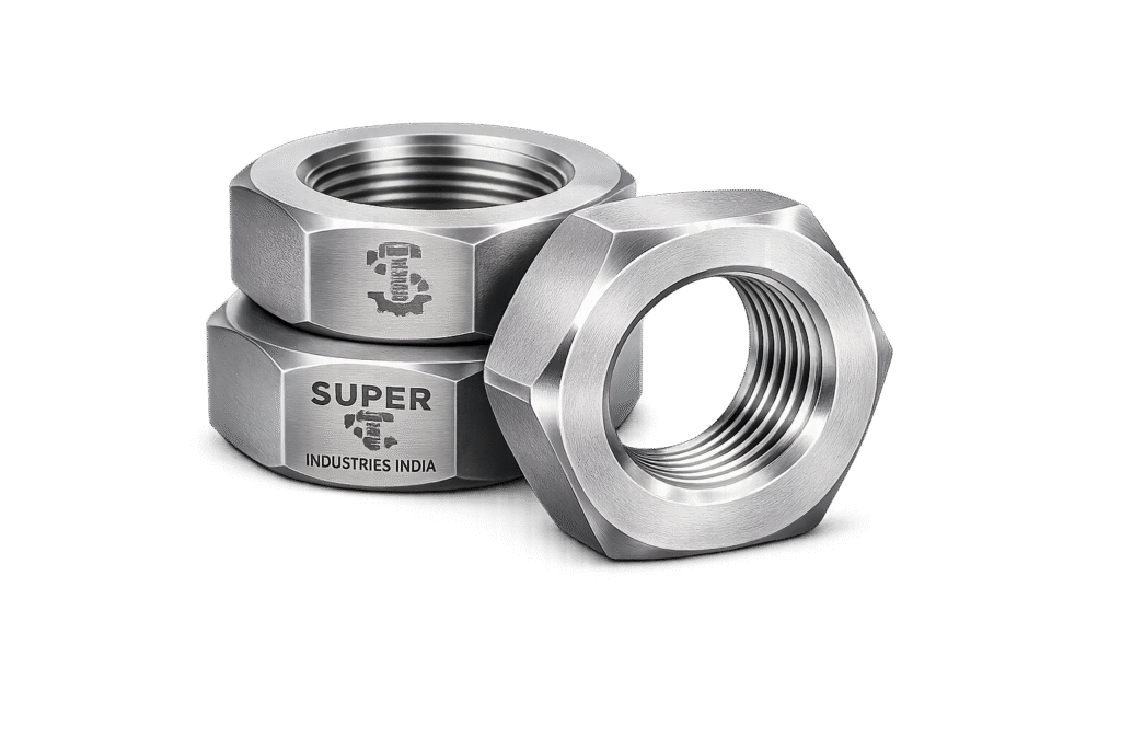
Role of Check Nuts in Bolted Fastening Systems
Check Nuts (Lock Nuts) are deployed as a secondary locking element within threaded fastening assemblies to maintain joint integrity under dynamic service conditions. Their function is not primary load bearing, but preload stabilization and resistance to self-loosening.
In bolted joints subjected to vibration, cyclic loading, thermal expansion, or mechanical shock, loss of preload is the primary failure mode. Once preload is reduced:
- Joint separation may occur
- Micro-movements initiate fretting
- Fastener fatigue life reduces
- Progressive loosening leads to functional failure
Check Nuts are used to mechanically inhibit rotation of the primary nut, ensuring that the clamping force remains within design limits over time.
System-Level Function
In a standard bolted assembly:
- Primary Nut → Establishes required preload
- Check Nut (Secondary Nut) → Locks the primary nut in position
This dual-nut configuration introduces frictional locking at thread interfaces, significantly increasing resistance to rotational loosening.
Application Domains
Check Nuts are specified in systems where:
- Preload retention is critical
- Dynamic loads are present
- Periodic maintenance access may be limited
Typical Applications
Oil & Gas Equipment
- Compressor casings
- Flange joints in pipelines
- Rotating assemblies
Power Generation
- Steam and gas turbines
- Boiler structural assemblies
- Generator housings
Rotating Equipment
- Pumps
- Gearboxes
- High-speed shafts
Structural Systems
- Steel structures
- Bridge bolting systems
- Load-bearing connections
Heavy Machinery
- Excavators
- Crushers
- Mining equipment
Railways & Infrastructure
- Track fastening systems
- Bogie assemblies
Automotive & Mobile Equipment
- Suspension systems
- Engine mounting assemblies
Why Check Nuts Are Used Alongside Primary Nuts
A single nut relies entirely on thread friction and preload. Under real operating conditions:
- Vibration reduces friction coefficient
- Surface embedment reduces clamping force
- Thermal cycling induces expansion/contraction
A Check Nut introduces:
- Opposing thread pressure
- Localized locking torque
- Increased breakaway torque
This creates a mechanical resistance barrier to rotation, independent of preload decay.
Failure Risks Without Locking Systems
Absence of a locking mechanism in critical joints may result in:
| Failure Mode | Engineering Impact |
|---|---|
| Self-loosening | Loss of preload |
| Joint separation | Leakage / misalignment |
| Fatigue failure | Crack initiation at threads |
| Component damage | Misaligned rotating parts |
| Safety risk | Structural instability |
Comparison with Other Locking Methods
| Locking Method | Mechanism | Limitations vs Check Nuts |
|---|---|---|
| Nylock Nuts | Nylon insert friction | Temperature limitation (~120°C) |
| Spring Washers | Elastic deformation | Limited vibration resistance |
| Thread Locking Adhesives | Chemical bonding | Requires curing, not reusable |
| Serrated Flange Nuts | Surface grip | Ineffective on hardened surfaces |
| Check Nuts | Mechanical jam effect | Requires correct installation sequence |
Engineering Observation:
Check Nuts remain one of the most reliable mechanical locking methods for high-temperature and heavy-duty applications, where polymer-based or chemical locking systems are unsuitable.
2. Technical Definition
Formal Definition
A Check Nut (Lock Nut) is a secondary threaded fastener installed against a primary nut to prevent loosening by creating frictional interference and load redistribution within the threaded assembly.
Functional Characteristics
- Installed after primary nut tightening
- Creates counteracting thread forces
- Increases loosening torque requirement
- Stabilizes axial preload
Double Nut System (Jam Nut Principle)
The system consists of:
- Primary Nut (Load Nut)
- Provides required clamping force
- Check Nut (Jam Nut)
- Locks the primary nut by applying reverse pressure
Types of Check Nuts
1. Thin Nuts (Jam Nuts)
- Reduced height (~0.5 × standard nut thickness)
- Used primarily as locking element
- Minimal thread engagement
2. Full-Height Lock Nuts
- Similar thickness to standard nuts
- Used where additional strength is required
- Can act as both primary and locking nut
Thread Compatibility
Check Nuts are manufactured for:
- Metric Threads (ISO)
- UNC (Unified National Coarse)
- UNF (Unified National Fine)
Thread standards must match:
- Bolt thread profile
- Pitch
- Tolerance class
Thread Engagement Behavior
In a double nut system:
- The primary nut fully engages threads for load transfer
- The check nut partially engages threads, applying locking pressure
Critical parameters:
- Minimum thread engagement: ≥ 1 × bolt diameter (primary nut)
- Check nut engagement: ≥ 0.5 × diameter (typical)
Super Industries
Global Manufacturer of Heavy & Custom Engineered Fasteners & Flanges
3. Engineering & Locking Principle
Bolt Preload Mechanics
Preload is generated when torque is applied:
- Torque induces tensile stress in the bolt
- This creates clamping force across the joint
Relationship:
- Torque → Friction + Thread force
- Only ~10–15% of torque contributes to preload
- Remaining torque is lost in friction
Frictional Locking Mechanism
When a Check Nut is tightened against a primary nut:
- Opposing Forces Develop
- Primary nut pushes against joint
- Check nut pushes against primary nut
- Thread Flank Pressure Increases
- Contact stress rises at thread interfaces
- Friction Coefficient Increases Locally
- Higher resistance to rotation
Load Redistribution Between Nuts
- Primary nut carries major axial load
- Check nut introduces reverse axial force
- This results in:
- Increased thread contact pressure
- Reduced likelihood of micro-movement
Thread Flank Interference
The locking effect arises from:
- Contact between opposing thread flanks
- Elastic deformation at contact surfaces
- Increased normal force → increased friction
Torque vs Preload Relationship
In a double nut system:
- Initial torque applied to primary nut sets preload
- Secondary torque applied to check nut increases:
- Friction at threads
- Resistance to loosening
Effect of Tightening Sequence
Correct sequence:
- Tighten primary nut to specified torque
- Hold primary nut in position
- Tighten check nut against primary nut
Incorrect sequence may:
- Reduce preload
- Cause uneven load distribution
- Reduce locking efficiency
Locking Efficiency Under Vibration
Check Nuts improve:
- Breakaway torque
- Resistance to cyclic rotation
- Stability under transverse vibration
They are particularly effective in:
- Low-frequency vibration systems
- High-mass rotating equipment
Loosening Torque Increase (Jam Effect)
The presence of a check nut results in:
- Increase in required loosening torque
- Formation of a mechanical barrier to rotation
This is due to:
- Combined friction from two thread interfaces
- Opposing axial forces
Micro-Slip Prevention Mechanism
In vibrating systems:
- Micro-slip occurs at thread interfaces
- Leads to gradual loosening
Check Nuts:
- Increase contact stiffness
- Reduce relative movement between threads
- Prevent progressive loosening
Engineering Summary of Locking Principle
| Parameter | Without Check Nut | With Check Nut |
|---|---|---|
| Preload retention | Moderate | High |
| Vibration resistance | Low–Moderate | High |
| Loosening torque | Low | Increased |
| Thread stability | Variable | Controlled |
| Joint reliability | Conditional | Enhanced |
Design Considerations for Engineers
When specifying Check Nuts:
- Match nut grade with bolt grade
- Ensure compatible thread tolerances
- Account for additional tightening torque
- Evaluate service temperature and environment
4. Applicable Standards (ASTM / DIN / ISO)
Check Nuts (Lock Nuts) are governed by multiple international standards that define dimensional tolerances, material properties, mechanical strength, and inspection requirements. Selection of the appropriate standard depends on application type, load conditions, and service environment.
ISO Standards
ISO 4035 — Hexagon Thin Nuts (Jam Nuts)
- Defines reduced-height nuts used primarily as check nuts
- Typical thickness: ~0.5 × nominal diameter
- Designed for locking applications, not primary load bearing
Application Relevance:
- Secondary locking in mechanical assemblies
- Suitable for low-to-moderate load locking systems
ISO 4032 — Hexagon Full Nuts
- Standard full-height hex nuts
- Used as primary or secondary nut depending on design
Application Relevance:
- When check nut must also withstand partial load sharing
- Used in heavy-duty bolted joints
DIN Standards
DIN 439 — Hexagon Thin Nuts (Jam Nuts)
- Equivalent to ISO 4035 with minor dimensional variations
- Widely used in European EPC projects
Variants:
- Type A: Standard chamfer
- Type B: Alternative dimensional tolerance
ASME / ANSI Standards
ASME B18.2.2 — Hex Nuts
- Covers:
- Hex nuts (full height)
- Jam nuts
- Defines:
- Inch-series threads (UNC/UNF)
- Dimensional tolerances
- Across flats and thickness
ASTM Material Standards
ASTM A563 — Carbon Steel Nuts
- Grades:
- Grade A → General structural
- Grade DH → High-strength structural
Applications:
- Structural bolting
- Infrastructure and heavy assemblies
ASTM A194 — Alloy & Stainless Steel Nuts
- Designed for high-pressure and high-temperature service
Key Grades:
| Grade | Material Type | Application |
|---|---|---|
| 2H | Carbon / Alloy Steel (Q&T) | Pressure vessels, flanges |
| 7 | Alloy Steel | High temperature service |
| 8 | Stainless Steel 304 | Corrosion resistance |
| 8M | Stainless Steel 316 | Marine / chemical |
Standards Mapping to Applications
| Application | Recommended Standard | Reason |
|---|---|---|
| Pressure vessels | ASTM A194 2H / 7 | High strength + temperature resistance |
| Structural steel | ASTM A563 DH | Load-bearing capability |
| General engineering | ISO 4032 / DIN 934 | Standard compatibility |
| Locking function only | ISO 4035 / DIN 439 | Thin nut configuration |
| Corrosive environment | ASTM A194 8 / 8M | Stainless steel performance |
Engineering Compliance Considerations
- Thread compatibility must align with:
- ISO metric system
- Unified thread system (UNC/UNF)
- Material grade must match:
- Bolt strength class
- Certification requirements:
- EN 10204 3.1 / 3.2
- Inspection standards:
- Third-party verification (if specified in EPC contract)
5. Material & Grade Options
Material selection for Check Nuts is based on:
- Mechanical strength requirements
- Environmental exposure
- Temperature conditions
- Compatibility with mating bolt
Carbon Steel Grades
ASTM A563 Grade A
- Low to medium strength
- Used in general structural applications
ASTM A563 Grade DH
- Heat-treated high-strength carbon steel
- Used with:
- High-strength bolts
- Structural assemblies
ASTM A194 Grade 2H
- Quenched and tempered carbon/alloy steel
- High strength and hardness
Typical Use:
- Flanges
- Pressure vessels
- High-load bolted joints
Stainless Steel Grades
ASTM A194 Grade 8 (SS 304)
- Austenitic stainless steel
- Good corrosion resistance
Limitations:
- Lower strength vs alloy steel
- Susceptible to galling
ASTM A194 Grade 8M (SS 316)
- Enhanced corrosion resistance due to molybdenum content
- Suitable for:
- Marine environments
- Chemical exposure
Alloy Steel Grades
ASTM A194 Grade 7
- High-temperature alloy steel
- Suitable for:
- Elevated temperature service
- Pressure systems
Material Selection Logic
| Parameter | Material Choice |
|---|---|
| High strength | A194 2H / A563 DH |
| Corrosion resistance | SS 304 / SS 316 |
| High temperature | A194 Gr 7 |
| Structural use | A563 DH |
| Chemical exposure | SS 316 |
Material Comparison Table
| Grade | Yield Strength (MPa) | Tensile Strength (MPa) | Temperature Range | Corrosion Resistance | Typical Application |
|---|---|---|---|---|---|
| A563 Gr A | ~250 | 400–550 | -20°C to 200°C | Low | General structures |
| A563 Gr DH | ~450 | 700–900 | -20°C to 300°C | Moderate | Structural bolting |
| A194 Gr 2H | ~650 | 850–1000 | -29°C to 425°C | Moderate | Pressure systems |
| A194 Gr 7 | ~720 | 900–1100 | Up to 500°C | Moderate | High-temperature service |
| A194 Gr 8 (304) | ~205 | 515–750 | -196°C to 400°C | High | Corrosive environments |
| A194 Gr 8M (316) | ~205 | 515–750 | -196°C to 450°C | Very High | Marine / chemical |
Engineering Notes
- Nut grade must be equal to or higher than bolt grade
- Stainless steel requires:
- Anti-galling lubrication
- High-temperature applications require:
- Material stability under creep conditions
6. Heat Treatment Information
Heat treatment ensures that Check Nuts meet mechanical property requirements such as:
- Strength
- Hardness
- Toughness
- Fatigue resistance
Common Heat Treatment Processes
1. Quenching & Tempering (Q&T)
- Heating to austenitizing temperature
- Rapid cooling (quenching)
- Controlled reheating (tempering)
Effect:
- High strength
- Improved toughness
Applicable to:
- ASTM A194 Gr 2H
- ASTM A563 DH
2. Normalizing
- Heating above critical temperature
- Air cooling
Effect:
- Uniform grain structure
- Moderate strength
3. Stress Relieving
- Low-temperature heat treatment
- Removes residual stresses
Effect:
- Improves dimensional stability
Hardness Ranges
| Grade | Hardness (HB / HRC) |
|---|---|
| A563 Gr A | 120–200 HB |
| A563 DH | 200–300 HB |
| A194 2H | 24–35 HRC |
| A194 Gr 7 | 28–36 HRC |
Impact on Thread Strength
- Proper heat treatment ensures:
- Thread deformation resistance
- Reduced risk of stripping
- Over-hardening may:
- Increase brittleness
- Reduce fatigue life
Impact Resistance
- Critical for:
- Low-temperature service
- Shock-loaded systems
Materials may require:
- Charpy impact testing
- Compliance with project specifications
7. Manufacturing Process
Manufacturing of Check Nuts follows a controlled, traceable process to ensure compliance with dimensional and mechanical standards.
Step-by-Step Process
1. Raw Material Inspection
- Chemical composition verification
- Mill test certificate validation
- Visual inspection
2. Forging / Forming
- Hot Forging
- Used for larger sizes
- Improves grain flow
- Cold Forming
- Used for smaller sizes
- Better dimensional precision
3. Thread Tapping
- Internal threading using:
- Tapping tools
- CNC-controlled machines
Thread standards:
- Metric (ISO)
- UNC / UNF
4. CNC Finishing
- Ensures:
- Accurate dimensions
- Surface finish control
5. Heat Treatment
- Applied as per grade requirement
- Controlled furnace conditions
6. Surface Coating
- Applied after machining and heat treatment
7. Inspection
- Dimensional verification
- Thread gauge testing
- Mechanical property testing
8. Marking & Traceability
- Grade marking
- Heat number
- Manufacturer identification
Dimensional Control Discipline
- Tolerance adherence:
- ISO 6H (metric threads)
- Class 2B (inch threads)
- Across flats:
- Verified using calibrated gauges
- Thickness:
- Critical for jam nut performance
Surface Finish Options
Surface finish impacts:
- Corrosion resistance
- Friction coefficient
- Torque-preload relationship
Common Surface Treatments
1. Zinc Plating
- Electroplated coating
- Moderate corrosion resistance
Use:
- Indoor / low exposure environments
2. Hot-Dip Galvanizing (HDG)
- Thick zinc coating
- High corrosion resistance
Consideration:
- Thread oversizing required
3. Black Oxide
- Minimal corrosion protection
- Maintains dimensional accuracy
4. Phosphate Coating
- Improves lubrication
- Used with oil coating
5. PTFE Coating
- Low friction
- Chemical resistance
6. Passivation (Stainless Steel)
- Removes free iron
- Enhances corrosion resistance
Effect on Torque
| Coating | Friction Level | Torque Impact |
|---|---|---|
| Zinc plated | Moderate | Standard torque |
| HDG | High | Increased torque required |
| PTFE | Low | Reduced torque |
| Phosphate | Controlled | Stable preload |
Engineering Consideration
Surface finish directly affects:
- Torque coefficient (K factor)
- Achievable preload
Therefore:
- Torque values must be adjusted based on coating type
A. Dimension Table — Check Nuts (Metric & UNC/UNF Reference)
Dimensional control of Check Nuts is critical for ensuring:
- Proper thread engagement
- Effective locking performance
- Compatibility with mating fasteners
Below is a generalized engineering reference table aligned with ISO 4035 / DIN 439 (thin nuts) and ASME B18.2.2 (inch series).
Metric Series (ISO / DIN)
| Thread Size | Pitch (mm) | Nut Thickness (mm) | Across Flats (mm) | Standard Type |
|---|---|---|---|---|
| M6 | 1.0 | 3.2 | 10 | ISO 4035 / DIN 439 |
| M8 | 1.25 | 4.0 | 13 | ISO 4035 / DIN 439 |
| M10 | 1.5 | 5.0 | 17 | ISO 4035 / DIN 439 |
| M12 | 1.75 | 6.0 | 19 | ISO 4035 / DIN 439 |
| M16 | 2.0 | 8.0 | 24 | ISO 4035 / DIN 439 |
| M20 | 2.5 | 10.0 | 30 | ISO 4035 / DIN 439 |
| M24 | 3.0 | 12.0 | 36 | ISO 4035 / DIN 439 |
| M30 | 3.5 | 15.0 | 46 | ISO 4035 / DIN 439 |
Inch Series (UNC / UNF)
| Nominal Size | Threads per Inch | Nut Thickness (in) | Across Flats (in) | Standard |
|---|---|---|---|---|
| 1/4″ | 20 (UNC) | 0.125 | 7/16 | ASME B18.2.2 |
| 3/8″ | 16 (UNC) | 0.188 | 9/16 | ASME B18.2.2 |
| 1/2″ | 13 (UNC) | 0.250 | 3/4 | ASME B18.2.2 |
| 5/8″ | 11 (UNC) | 0.312 | 15/16 | ASME B18.2.2 |
| 3/4″ | 10 (UNC) | 0.375 | 1-1/8 | ASME B18.2.2 |
| 1″ | 8 (UNC) | 0.500 | 1-1/2 | ASME B18.2.2 |
Engineering Notes
- Thin nut thickness ≈ 0.5 × nominal diameter
- Across flats must ensure tool compatibility
- Thread tolerance:
- Metric: 6H
- Inch: 2B
B. Torque Chart
Torque values depend on:
- Bolt diameter
- Material grade
- Surface condition (dry / lubricated)
- Friction coefficient
Indicative Torque Values for Carbon Steel (Property Class Equivalent to 8.8 / ASTM A194 2H)
| Bolt Size | Dry Torque (Nm) | Lubricated Torque (Nm) | Approx. Preload (kN) |
|---|---|---|---|
| M6 | 10 | 7 | 5 |
| M8 | 25 | 18 | 10 |
| M10 | 50 | 35 | 20 |
| M12 | 85 | 60 | 30 |
| M16 | 210 | 150 | 70 |
| M20 | 410 | 290 | 110 |
| M24 | 710 | 500 | 170 |
| M30 | 1400 | 980 | 300 |
Torque Application in Check Nut Systems
- Primary nut:
- Tightened to full specified torque
- Check nut:
- Typically tightened to 30–50% of primary torque
Engineering Considerations
- Lubrication reduces:
- Friction coefficient
- Required torque
- Coatings such as PTFE significantly alter:
- Torque-preload relationship
C. Preload Calculation Guide
Preload is the axial clamping force generated in a bolted joint. It is the primary factor governing joint performance.
Fundamental Torque–Preload Relationship
![\[F = \frac{T}{K \cdot d}\]](https://superindustriesindia.in/wp-content/ql-cache/quicklatex.com-047c3812ff26cb229181955bd579e870_l3.png "Rendered by QuickLaTeX.com")
Where:
- F = Preload force (N)
- T = Applied torque (Nm)
- K = Torque coefficient (typically 0.18–0.25)
- d = Nominal bolt diameter (m)
Engineering Interpretation
- Only a portion of applied torque generates preload
- Majority of torque is lost in:
- Thread friction
- Bearing surface friction
Sample Calculation
Given:
- Bolt size: M20 → d = 0.02 m
- Applied torque: 300 Nm
- Torque coefficient: K = 0.20
Calculation:
F = 300 / (0.20 × 0.02)
F = 300 / 0.004
F = 75,000 N (75 kN)
Effect of Friction Coefficient (K Factor)
| Condition | K Value | Effect on Preload |
|---|---|---|
| Dry | 0.22–0.25 | Lower preload |
| Lubricated | 0.18–0.20 | Higher preload |
| PTFE coated | 0.10–0.15 | Significantly higher preload |
Locking Torque Increase in Check Nut System
With a Check Nut:
- Effective friction increases
- Required loosening torque becomes:
Loosening Torque > Tightening Torque (Primary Nut)
This is due to:
- Opposing axial forces
- Thread flank pressure
Preload Stability Considerations
Factors affecting preload:
- Embedment losses
- Surface roughness
- Thermal expansion
- Vibration
Check Nuts improve:
- Preload retention
- Resistance to relaxation
D. Mechanical Properties Table
Mechanical properties must align with:
- ASTM / ISO material specifications
- Application load requirements
| Grade | Yield Strength (MPa) | Tensile Strength (MPa) | Hardness | Elongation (%) |
|---|---|---|---|---|
| A563 Gr A | ~250 | 400–550 | 120–200 HB | 20 |
| A563 DH | ~450 | 700–900 | 200–300 HB | 15 |
| A194 2H | ~650 | 850–1000 | 24–35 HRC | 12 |
| A194 Gr 7 | ~720 | 900–1100 | 28–36 HRC | 10 |
| A194 Gr 8 (304) | ~205 | 515–750 | 150–200 HB | 30 |
| A194 Gr 8M (316) | ~205 | 515–750 | 150–200 HB | 35 |
Engineering Notes
- Higher hardness improves:
- Wear resistance
- Thread integrity
- Lower elongation indicates:
- Reduced ductility
- Stainless steels provide:
- Higher elongation
- Lower yield strength
E. Corrosion Resistance Comparison Table
Corrosion resistance must be evaluated against:
- Environmental exposure
- Chemical interaction
- Temperature
| Material | Marine | Humidity | Chemical Exposure | Temperature Resistance |
|---|---|---|---|---|
| Carbon Steel | Low | Low | Poor | Moderate |
| Zinc Plated Steel | Moderate | Moderate | Limited | Moderate |
| SS 304 | Good | High | Moderate | High |
| SS 316 | Excellent | Very High | High | High |
| Alloy Steel (Gr 7) | Moderate | Moderate | Moderate | Very High |
Engineering Interpretation
- Marine environments → SS 316 preferred
- Indoor structural → Carbon steel sufficient
- Chemical plants → Stainless steel mandatory
- High-temperature → Alloy steel required
8. Inspection & Quality Control Methods
Inspection ensures compliance with:
- Dimensional standards
- Mechanical properties
- Material specifications
1. Thread Gauge Inspection
- GO / NO-GO gauges used
- Ensures:
- Correct pitch diameter
- Thread fit (6H / 2B)
2. Dimensional Inspection
- Across flats
- Thickness
- Thread depth
Tools:
- Vernier calipers
- Micrometers
- Coordinate measuring systems
3. Hardness Testing
Methods:
- Rockwell (HRC)
- Brinell (HB)
Purpose:
- Verify heat treatment
- Ensure compliance with grade
4. Proof Load Testing
- Confirms load-bearing capability
- Ensures nut does not deform under specified load
5. PMI (Positive Material Identification)
- Spectrographic analysis
- Verifies alloy composition
Applicable for:
- Stainless steel
- Alloy steel
6. Visual Inspection
- Surface defects
- Cracks
- Coating uniformity
7. Coating Thickness Testing
- Zinc / galvanizing thickness measurement
- Ensures corrosion protection compliance
8. Certification & Documentation
EN 10204 Certification
- 3.1 Certificate
- Manufacturer test report
- 3.2 Certificate
- Third-party validated report
9. Third-Party Inspection
Conducted by:
- Independent inspection agencies
Scope includes:
- Material verification
- Dimensional checks
- Mechanical testing
- Documentation review
Inspection Traceability
Each batch must include:
- Heat number
- Material grade marking
- Inspection records
9. Industries Served
Check Nuts (Lock Nuts) are specified across multiple industries where joint reliability, preload retention, and vibration resistance are critical to system performance and safety.
Oil & Gas Industry
Application Scope:
- Pipeline flange connections
- Pressure vessel assemblies
- Compressor and pump housings
- Offshore structural systems
Engineering Requirement:
- Resistance to vibration and pressure cycling
- Compatibility with ASTM A194 (Gr 2H / Gr 7)
- Performance under elevated temperatures
Failure Sensitivity:
- Loss of preload may lead to:
- Leakage
- Joint separation
- Operational shutdown
Power Generation Sector
Application Scope:
- Steam turbine casings
- Boiler structures
- Generator frames
- High-temperature bolted joints
Engineering Requirement:
- Thermal stability under cyclic expansion
- High preload retention over time
- Material suitability for creep conditions
Petrochemical & Process Plants
Application Scope:
- Chemical reactors
- Heat exchangers
- Structural pipe supports
Engineering Requirement:
- Corrosion resistance (SS 304 / SS 316)
- Chemical compatibility
- Long-term dimensional stability
Heavy Equipment & Mining
Application Scope:
- Crushers
- Excavators
- Dragline assemblies
- High-impact machinery
Engineering Requirement:
- Resistance to shock loads
- Fatigue resistance under cyclic loading
- Robust locking under vibration
Infrastructure & Structural Engineering
Application Scope:
- Steel structures
- Bridges
- Industrial frameworks
Engineering Requirement:
- Structural load integrity
- Long-term preload retention
- Compatibility with ASTM A563 DH
Railways
Application Scope:
- Bogie assemblies
- Track fastening systems
- Suspension components
Engineering Requirement:
- Resistance to continuous vibration
- High fatigue life
- Consistent locking performance
Marine & Offshore
Application Scope:
- Offshore platforms
- Ship structures
- Deck equipment
Engineering Requirement:
- Corrosion resistance (SS 316 / coated alloy steel)
- Saltwater exposure durability
- Long service intervals
Automotive & Mobile Equipment
Application Scope:
- Engine mounts
- Suspension systems
- Load-bearing joints
Engineering Requirement:
- Compact locking solutions
- Resistance to dynamic loads
- Repeatable tightening performance
10. Export Capability & Global Supply
Super Industries operates as a manufacturer and global exporter of Check Nuts, aligned with EPC project supply requirements.
Export Regions
- United States
- Compliance with ASTM / ASME standards
- European Union
- DIN / ISO compliance
- Middle East
- Oil & gas project supply
- Southeast Asia
- Infrastructure and power projects
Packaging Standards
Packaging is designed to ensure:
- Protection against corrosion
- Mechanical damage prevention
- Traceability maintenance
Typical Packaging Types:
- Export-grade wooden boxes
- Palletized shipments
- Moisture-resistant packing
- Vacuum packing (for stainless steel when required)
Marking & Identification
Each batch includes:
- Grade marking
- Size identification
- Heat number traceability
- Manufacturer identification
Marking complies with:
- ASTM / ISO requirements
- Project-specific specifications
Export Documentation
Standard documentation includes:
- Commercial invoice
- Packing list
- Mill Test Certificates (MTC)
- EN 10204 3.1 / 3.2 certification
- Third-party inspection reports (if specified)
- Certificate of origin
Project Supply Capability
Super Industries supports:
- Bulk supply for EPC projects
- Mixed-size fastener packages
- Custom specification manufacturing
- Lot-wise traceability
11. PROCUREMENT & INSTALLATION VIEW
Double Nut Tightening Sequence
Correct installation is critical for achieving locking effectiveness and preload stability.
Recommended Tightening Procedure
- Install Primary Nut
- Tighten to specified torque value
- Hold Primary Nut in Position
- Prevent rotation during second step
- Install Check Nut
- Tighten against primary nut
- Apply Locking Torque
- Typically 30–50% of primary torque
Jam Nut Tightening Method
Two accepted methods:
Method A — Standard Locking
- Primary nut tightened first
- Check nut tightened against it
Method B — Reverse Jam Method
- Thin nut tightened first
- Primary nut tightened against it
Engineering Preference:
- Method A is commonly used for critical load applications
Torque Application Order
| Step | Component | Torque Level |
|---|---|---|
| 1 | Primary Nut | 100% design torque |
| 2 | Check Nut | 30–50% of primary torque |
Re-Torque Practice
- Required in:
- High-temperature systems
- Critical joints
Procedure:
- Inspect preload condition
- Reapply torque if relaxation is observed
Field Inspection Checkpoints
- Thread engagement length
- Correct nut positioning
- Torque verification
- Presence of lubrication (if required)
- Coating condition
Storage Conditions
To maintain performance:
- Store in dry, covered environment
- Avoid:
- Moisture exposure
- Chemical contamination
For stainless steel:
- Prevent cross-contamination with carbon steel
Super Industries provides manufacturing support for project-specific Check Nuts.
12. CUSTOM ENGINEERING CAPABILITIES
Customization Scope
1. Non-Standard Thread Sizes
- Oversized diameters
- Special pitch requirements
- Custom thread profiles
2. Special Coatings
- PTFE for low friction
- Heavy galvanizing for marine use
- Custom anti-corrosion coatings
3. High-Strength Custom Nuts
- Higher grade materials
- Enhanced heat treatment cycles
- Application-specific mechanical properties
4. Project-Specific Marking
- Client identification
- Heat number tracking
- Inspection agency marking
Engineering Control in Customization
- Design validation against:
- Load requirements
- Environmental conditions
- Compliance with:
- Applicable international standards
- Documentation alignment with:
- EPC specifications
ENGINEERING CONCLUSION
Check Nuts (Lock Nuts) function as a mechanical locking mechanism within bolted assemblies, designed to:
- Prevent self-loosening
- Maintain preload stability
- Enhance joint reliability under dynamic conditions
System-Level Engineering Value
When properly specified and installed, Check Nuts provide:
- Increased resistance to vibration-induced loosening
- Improved preload retention
- Controlled thread interaction
- Enhanced operational safety
Critical Design Considerations
For EPC and engineering applications, the following must be ensured:
- Correct material grade selection
- Compliance with ASTM / ISO / DIN standards
- Accurate torque-preload relationship
- Proper installation sequence
- Verified inspection and certification
Performance Dependencies
The effectiveness of Check Nuts depends on:
- Thread fit accuracy
- Surface condition and lubrication
- Proper torque application
- Compatibility with mating fasteners
Final Engineering Statement
A Check Nut system is not a substitute for correct preload—it is a supplementary locking mechanism that enhances the stability of a properly designed bolted joint.
When evaluated from an EPC and consultant perspective, a compliant Check Nut supply must demonstrate:
- Dimensional precision
- Material traceability
- Mechanical property compliance
- Inspection readiness
- Application-specific suitability