
FLANGEOLET
Super Industries
“Global Manufacturer of Heavy & Custom Engineered Fasteners for Oil & Gas, Power & EPC Contractors.”
1. Industry Context & System Relevance
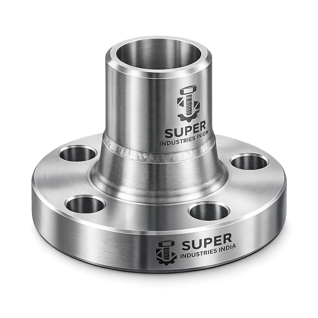
In high-integrity piping systems, branch connections represent one of the most critical structural discontinuities in the pressure boundary. A Flangeolet is deployed where a branch connection must not only maintain pressure integrity but also provide a detachable, flanged interface for downstream piping or equipment.
Role of Flangeolet in Piping Systems
A Flangeolet is used to create a reinforced branch outlet on a header pipe, while simultaneously providing a flanged connection for:
- Valve installation
- Instrumentation take-off
- Secondary pipeline connection
- Maintenance-accessible branch systems
It integrates branch reinforcement and flanged termination into a single engineered component.
Primary Application Domains
Flangeolets are used extensively in:
Oil & Gas Pipelines
- High-pressure transmission lines
- Pigging stations and bypass lines
- Metering skids
Refineries & Petrochemical Plants
- Process unit tie-ins
- Utility connections (steam, condensate)
- Flare systems
Offshore Platforms
- Compact piping layouts
- High fatigue and vibration zones
Power Plants
- Boiler feedwater systems
- High-pressure steam extraction points
LNG & Cryogenic Systems
- Controlled branch take-offs with minimal leakage risk
Hydrogen & High-Purity Systems
- Where flange accessibility is critical for inspection and replacement
Why Branch Reinforcement is Required
When a hole is introduced into a pipe to create a branch:
- The load-bearing cross-sectional area is reduced
- Stress flow is disrupted
- Local stress concentration increases significantly
Without reinforcement:
- Hoop stress increases locally
- Crack initiation risk rises
- Fatigue life reduces
Engineering Requirement
Branch connections must satisfy area replacement criteria per piping codes such as ASME B31.3.
Comparison with Other Branch Fittings
| Fitting Type | Connection Type | Reinforcement | Outlet Type | Typical Use |
|---|---|---|---|---|
| Weldolet | Butt-weld | Integral | Plain pipe | Permanent branch |
| Sockolet | Socket weld | Moderate | Socket | Small bore |
| Threadolet | Threaded | Moderate | Threaded | Low pressure |
| Stub-in | Direct weld | External pad required | Pipe | Fabricated solution |
| Flangeolet | Butt-weld + Flange | Integral | Flanged | Detachable branch |
Why Flange-Integrated Branch Connections Are Selected
Flangeolets are selected when:
- Frequent disassembly is required
- Equipment connection is needed
- Inspection accessibility is mandatory
- Field flexibility is necessary
They eliminate the need for:
- Separate flange welding
- Additional reinforcement pads
- Complex fabrication
2. Technical Definition of Flangeolet
A Flangeolet is defined as:
An integrally reinforced branch connection fitting with a contoured butt-weld inlet and an integral flanged outlet, designed in accordance with MSS SP-97 for installation on a header pipe.
Key Characteristics
- Inlet End: Contoured to match header pipe curvature
- Connection: Butt-weld to header
- Outlet: Integral flange (RF or RTJ)
- Design Basis: MSS SP-97
- Pressure Integrity: Equivalent to header pipe under design conditions
MSS SP-97 Compliance
MSS SP-97 defines:
- Dimensional requirements
- Reinforcement geometry
- Material specifications
- Pressure-temperature limits
Flangeolets under this standard:
- Provide self-reinforced geometry
- Eliminate need for reinforcement pads
- Maintain pressure boundary continuity
Geometry & Configuration
A Flangeolet consists of:
- Branch Saddle (Contoured Base)
- Reinforcement Hub
- Integral Flange
- Weld Bevel Interface
Pressure Boundary Characteristics
- Designed to withstand:
- Internal pressure
- External loads
- Thermal expansion forces
- Stress is redistributed via reinforced hub geometry
Super Industries
Global Manufacturer of Heavy & Custom Engineered Fasteners & Flanges
3. Engineering & Reinforcement Principle
Branch Reinforcement Theory
Branch reinforcement is governed by area replacement method:
Area removed from header = Area compensated by reinforcement
Sources of Reinforcement
- Excess wall thickness of header
- Thickness of branch fitting
- Weld metal contribution
Stress Distribution Mechanism
In a pressurized pipe:
- Hoop stress flows circumferentially
- Branch opening interrupts stress flow
- Flangeolet redistributes stress via reinforced geometry
Internal Pressure Stress Flow
Without reinforcement:
- Stress lines converge at branch edge
- High localized stress occurs
With Flangeolet:
- Stress is smoothly redistributed
- Peak stress is reduced
Weld Integrity Considerations
Critical weld:
- Butt weld between header and Flangeolet
Requirements:
- Full penetration weld
- Qualified WPS (ASME Section IX)
- Controlled heat input
Reinforcement Pad vs Integrally Reinforced Fitting
| Parameter | Reinforcement Pad | Flangeolet |
|---|---|---|
| Fabrication complexity | High | Low |
| Inspection difficulty | High | Low |
| Stress distribution | Non-uniform | Optimized |
| Fatigue resistance | Moderate | High |
Fatigue Resistance Under Cyclic Pressure
Flangeolets perform better under:
- Pressure cycling
- Thermal cycling
- Vibration
Due to:
- Smooth stress transition
- Absence of sharp discontinuities
4. Pressure & Load Engineering
ASME Pressure Class Compatibility
Flangeolets are manufactured for:
- Class 150
- Class 300
- Class 600
- Class 900
- Class 1500
- Class 2500
Branch vs Header Pressure Relationship
Design considerations:
- Branch pressure must not exceed header rating
- Reinforcement must satisfy:
- Internal pressure loads
- External piping loads
Thermal Expansion Effects
Thermal loads cause:
- Axial stress
- Bending stress
- Secondary stress at branch
Flangeolet must accommodate:
- Expansion mismatch
- Anchor constraints
Cyclic Fatigue & Vibration
Critical in:
- Offshore systems
- Compressor discharge lines
- High-flow pipelines
Flangeolet advantages:
- Reduced stress concentration
- Improved fatigue life
Stress Intensification Factors (SIF)
Branch connections increase local stress.
Flangeolets:
- Have lower SIF compared to fabricated tees
- Improve system flexibility performance
Flexibility Analysis Relevance
Used in:
- CAESAR II simulations
- Stress modeling
Flangeolets are modeled as:
- Reinforced branch elements
- With defined SIF values
Burst Margin Philosophy
Design ensures:
- Burst pressure >> design pressure
- Safety margin aligned with ASME codes
Dimensional & Design Logic
Run Pipe vs Branch Size Relationship
- Branch size ≤ Run pipe size
- Typically:
- 1/2″ to 24″ branch sizes
- Larger sizes on request
Outlet Flange Rating
Defined as per:
- ASME B16.5
- Must match system rating
Centerline Geometry
- Branch centerline intersects header centerline
- Offset controlled for:
- Flow efficiency
- Structural balance
Welding Bevel Geometry
- 37.5° bevel typical
- Root gap controlled
- Machined for precision fit
Flange Face Types
- Raised Face (RF)
- Ring Type Joint (RTJ)
Dimensional Tolerances
Controlled for:
- Fit-up accuracy
- Alignment
- Welding quality
Surface Finish Requirements
- Flange face finish:
- 125–250 AARH (typical RF)
- Machined surfaces:
- Free from tool marks
5. Applicable Standards (ASTM / ASME / MSS / ISO)
The design, manufacture, and application of a Flangeolet are governed by a combination of dimensional, material, and piping code standards. Compliance with these standards ensures interchangeability, pressure integrity, and acceptance in EPC project environments.
MSS SP-97 — Primary Standard for Olets
Scope:
- Covers integrally reinforced branch outlet fittings
- Defines:
- Geometry and contour
- Reinforcement requirements
- Dimensional tolerances
- Marking requirements
Relevance to Flangeolet:
- Establishes the design basis for branch reinforcement
- Ensures compatibility with header pipe curvature
- Governs stress distribution characteristics
ASME B16.5 — Flanged Outlet Standard
Scope:
- Covers pipe flanges and flanged fittings from NPS ½” to 24”
- Defines:
- Pressure classes (150–2500)
- Bolt circle dimensions
- Facing types (RF, RTJ)
- Surface finish requirements
Application in Flangeolet:
- Governs the integral flange portion
- Ensures:
- Interchangeability with mating flanges
- Bolt alignment accuracy
- Gasket sealing compatibility
ASME B31.3 — Process Piping Code
Scope:
- Governs design of piping systems in:
- Refineries
- Chemical plants
- Petrochemical facilities
Relevance:
- Defines branch reinforcement rules
- Establishes:
- Allowable stress limits
- Load combinations
- Flexibility requirements
Critical Clause:
- Branch connections must satisfy area replacement criteria
ASTM Material Standards
Define mechanical and chemical properties of materials used in Flangeolets.
| Material Type | Standard |
|---|---|
| Carbon Steel | ASTM A105 |
| Low Temp CS | ASTM A350 LF2 |
| Stainless Steel | ASTM A182 F304 / F316 |
| Alloy Steel | ASTM A182 F11 / F22 |
| Duplex | ASTM A182 F51 / F53 |
EN / DIN / ISO Equivalents
For European and international projects:
| System | Equivalent Standard |
|---|---|
| EN | EN 10253 / EN 1092 |
| DIN | DIN 2615 / DIN 2633 |
| ISO | ISO 7005 |
Standards Mapping to Service Conditions
| Service Condition | Applicable Standards |
|---|---|
| High Pressure | ASME B16.5 + MSS SP-97 |
| High Temperature | ASTM A182 Alloy Grades |
| Low Temperature | ASTM A350 LF2 |
| Corrosive Service | ASTM A182 F316 / Duplex |
| Offshore | NACE + ASME + MSS |
6. Material & Grade Options
Material selection for a Flangeolet is based on:
- Pressure-temperature conditions
- Corrosion environment
- Weldability
- Mechanical strength requirements
Carbon Steel
ASTM A105
- Standard forging grade
- Suitable for:
- Ambient to moderate temperatures
- General refinery service
Characteristics:
- Good weldability
- Moderate corrosion resistance
- Cost-effective
ASTM A350 LF2
- Designed for low-temperature service
Characteristics:
- Improved toughness
- Charpy impact tested
- Suitable for sub-zero conditions
Stainless Steel
ASTM A182 F304
- Austenitic stainless steel
- General corrosion resistance
ASTM A182 F316
- Molybdenum-enhanced grade
Advantages:
- Superior resistance to:
- Chlorides
- Marine environments
- Chemical exposure
Duplex & Super Duplex Stainless Steel
- ASTM A182 F51 (Duplex)
- ASTM A182 F53 (Super Duplex)
Characteristics:
- High strength (≈2× austenitic SS)
- Excellent corrosion resistance
- Suitable for offshore and subsea
Alloy Steel
ASTM A182 F11 / F22
- Chromium-molybdenum steels
Applications:
- High-temperature service
- Power plants
- Steam lines
Material Selection Considerations
| Parameter | Impact |
|---|---|
| Temperature | Determines allowable stress |
| Pressure | Requires higher strength |
| Corrosion | Drives SS/Duplex selection |
| Weldability | Influences fabrication |
| Cost | Project budget constraint |
Material Comparison Table
| Grade | Yield Strength (MPa) | Tensile Strength (MPa) | Temperature Range | Corrosion Resistance | Typical Use |
|---|---|---|---|---|---|
| ASTM A105 | 250 | 485 | -29°C to 425°C | Low | General oil & gas |
| ASTM A350 LF2 | 250 | 485 | -46°C to 345°C | Low | Low-temp service |
| ASTM A182 F304 | 205 | 515 | -196°C to 870°C | Moderate | Chemical plants |
| ASTM A182 F316 | 205 | 515 | -196°C to 870°C | High | Marine / corrosive |
| Duplex F51 | 450 | 620 | -50°C to 300°C | Very High | Offshore |
| Super Duplex F53 | 550 | 750 | -50°C to 300°C | उत्कृष्ट | Subsea |
| F11 | 275 | 415 | Up to 540°C | Moderate | Power |
| F22 | 415 | 585 | Up to 600°C | Moderate | High-temp |
7. Heat Treatment Information
Heat treatment ensures required mechanical properties and microstructural stability.
Normalizing
- Refines grain structure
- Improves uniformity
Used for:
- Carbon steel (A105)
Quenching & Tempering (Q&T)
- Increases strength and toughness
Used for:
- Alloy steels (F11, F22)
Solution Annealing
- Dissolves carbides
- Restores corrosion resistance
Used for:
- Stainless steel
- Duplex grades
Stress Relieving
- Reduces residual stresses from:
- Forging
- Machining
Heat Treatment Control Parameters
| Parameter | Importance |
|---|---|
| Temperature control | Prevents grain coarsening |
| Cooling rate | Controls hardness |
| Holding time | Ensures uniformity |
Hardness Control
- Prevents brittle failure
- Ensures machinability
Typical limits:
- CS: ≤ 187 HB
- Alloy: As per ASTM
- Duplex: Controlled to avoid phase imbalance
Microstructure Considerations
- Fine grain structure preferred
- Avoid:
- Carbide precipitation
- Sigma phase (duplex)
Charpy Impact Testing
Required for:
- Low-temperature service
- Offshore applications
Ensures:
- Toughness at design temperature
8. Manufacturing Process
The manufacturing of a Flangeolet follows a controlled, traceable sequence to ensure compliance with EPC project requirements.
Raw Material Inspection
- Mill test certificate verification
- PMI (Positive Material Identification)
- Visual inspection
Forging Process
Closed Die Forging
- For standard sizes
- Ensures dimensional consistency
Open Die Forging
- For large/custom sizes
Rough Machining
- Removal of excess material
- Preparation for precision machining
Branch Contour Machining
- CNC profiling to match pipe OD
- Ensures:
- Full contact fit
- Proper weld geometry
Flange Facing
- Machining of:
- RF / RTJ face
- Bolt holes
- Bore
Drilling & Boring
- Bolt hole drilling
- Bore alignment with branch axis
Heat Treatment
- As per material specification
- Controlled furnace cycles
Surface Finishing
- Removal of scale
- Shot blasting (if required)
Marking & Traceability
Each Flangeolet is marked with:
- Heat number
- Material grade
- Size and rating
- Manufacturer identification
Traceability System
- Heat-wise traceability
- Linked to:
- MTC
- Inspection reports
- Test certificates
9. Surface Finish Options
Surface protection depends on material and service environment.
Carbon Steel Protection
- Anti-rust coating
- Black oxide coating
- Zinc plating
- Hot-dip galvanizing
Stainless Steel Protection
- Pickling & passivation
- Removes:
- Free iron
- Surface contaminants
Flange Face Finish
As per ASME B16.5:
| Face Type | Finish |
|---|---|
| RF | 125–250 AARH |
| RTJ | Smooth, groove finish |
Surface Finish Requirements
- No dents or scratches on sealing face
- Proper serration pattern for gasket seating
- Clean machining marks
A. Dimensional Tables
Dimensional control for a Flangeolet is governed by MSS SP-97 (branch geometry) and ASME B16.5 (flange interface). The following table provides representative engineering data used during design verification and procurement evaluation.
Note: Final dimensions depend on manufacturer design calculations and project specifications.
Typical Dimensional Table
| Run Size (NPS) | Branch Size (NPS) | Flange Class | Center-to-Face (mm) | Hub Height (mm) | Approx Weight (kg) |
|---|---|---|---|---|---|
| 6″ | 2″ | 300 | 140 | 85 | 8.5 |
| 8″ | 3″ | 300 | 165 | 95 | 12 |
| 10″ | 4″ | 600 | 190 | 110 | 18 |
| 12″ | 6″ | 600 | 220 | 130 | 28 |
| 16″ | 8″ | 900 | 260 | 150 | 45 |
| 20″ | 10″ | 1500 | 310 | 180 | 72 |
Dimensional Engineering Considerations
- Center-to-Face Distance:
- Affects piping layout and isometric design
- Hub Height:
- Determines reinforcement effectiveness
- Weight:
- Required for:
- Support design
- Lifting planning
- Transportation calculations
- Required for:
B. Pressure Rating Table
Pressure ratings of Flangeolets are derived from ASME B16.5 flange ratings combined with material allowable stresses.
Class vs Pressure vs Temperature (Carbon Steel Example)
| Class | 38°C (bar) | 200°C (bar) | 400°C (bar) |
|---|---|---|---|
| 150 | 19.6 | 15.3 | 10.2 |
| 300 | 51.1 | 40.0 | 26.7 |
| 600 | 102.1 | 80.1 | 53.4 |
| 900 | 153.2 | 120.2 | 80.1 |
| 1500 | 255.3 | 200.3 | 133.5 |
| 2500 | 425.5 | 333.8 | 222.5 |
Engineering Notes
- Ratings reduce with temperature increase
- Material grade directly influences allowable stress
- Must comply with ASME B16.5 pressure-temperature tables
C. Torque Chart
Bolt tightening for the flange outlet of a Flangeolet must ensure proper gasket compression without overstressing bolts.
Indicative Torque Values (Carbon Steel Bolting)
| Bolt Size | Torque (Nm) – Dry | Torque (Nm) – Lubricated |
|---|---|---|
| M16 | 120 | 90 |
| M20 | 240 | 180 |
| M24 | 410 | 310 |
| M27 | 600 | 450 |
| M30 | 820 | 615 |
| M36 | 1450 | 1100 |
Torque Engineering Considerations
- Lubrication reduces friction → lower torque required
- Over-tightening may cause:
- Flange distortion
- Gasket damage
- Tightening sequence:
- Cross-pattern method
- Multi-stage tightening (30% → 60% → 100%)
D. Reinforcement Calculation Guide
Branch reinforcement for a Flangeolet must satisfy the area replacement requirement as per ASME B31.3.
Area Replacement Principle

Where:
- ( A_{required} ) = Area removed from header pipe
- ( A_{available} ) = Area provided by:
- Excess pipe wall
- Flangeolet reinforcement
- Weld metal
Detailed Formula Representation
A_r = d \times t_h

Worked Example (Simplified)
Given:
- Header OD hole diameter (d) = 100 mm
- Header thickness (tₕ) = 10 mm
Area Removed:

Available Reinforcement:
- Flangeolet hub contribution = 700 mm²
- Excess pipe thickness = 200 mm²
- Weld metal = 150 mm²

Engineering Conclusion
Since:

→ Design is acceptable
Stress Check Logic
- Verify hoop stress around branch
- Confirm allowable stress limits
- Validate using piping code equations
E. Mechanical Property Table
| Material | Yield Strength (MPa) | Tensile Strength (MPa) | Elongation (%) | Hardness (HB) |
|---|---|---|---|---|
| A105 | 250 | 485 | 22 | ≤187 |
| LF2 | 250 | 485 | 22 | ≤187 |
| F304 | 205 | 515 | 30 | ≤201 |
| F316 | 205 | 515 | 30 | ≤201 |
| Duplex F51 | 450 | 620 | 25 | ≤290 |
| F22 | 415 | 585 | 20 | ≤220 |
F. Corrosion Resistance Table
| Material | Corrosion Resistance | Chloride Resistance | Sour Service Suitability | Typical Environment |
|---|---|---|---|---|
| Carbon Steel | Low | Poor | Limited | Dry systems |
| SS304 | Moderate | Moderate | Limited | General chemical |
| SS316 | High | High | Good | Marine |
| Duplex | Very High | Excellent | Excellent | Offshore |
| Alloy Steel | Moderate | Low | Moderate | High-temp |
10. Inspection & Quality Control Methods
Inspection of a Flangeolet is mandatory to ensure compliance with project specifications and international standards.
Positive Material Identification (PMI)
- Verifies alloy composition
- Conducted using:
- XRF analyzer
- Ensures:
- Correct grade selection
- Traceability integrity
Ultrasonic Testing (UT)
- Detects internal discontinuities
- Applicable for:
- Forged components
- Identifies:
- Inclusions
- Voids
Magnetic Particle Inspection (MPI)
- Surface and near-surface defect detection
- Applicable for:
- Carbon and alloy steels
Dye Penetrant Inspection (DPI)
- Used for:
- Stainless steel
- Detects:
- Surface cracks
- Porosity
Dimensional Inspection
Verification of:
- Branch contour
- Flange thickness
- Bolt hole alignment
- Centerline accuracy
Hardness Testing
Ensures compliance with:
- Material standards
- Heat treatment requirements
Hydro Testing
- Confirms pressure integrity
- Conducted as per project requirement
EN 10204 Certification
| Certificate Type | Description |
|---|---|
| 3.1 | Manufacturer test certificate |
| 3.2 | Third-party witnessed certification |
Third-Party Inspection
Typically conducted by:
- Client-appointed inspectors
- International agencies
Includes:
- Stage inspection
- Final inspection
- Documentation verification
Inspection Documentation Package
- Mill Test Certificates (MTC)
- Heat treatment charts
- NDT reports
- Dimensional reports
- PMI reports
11. Industries Served
A Flangeolet is deployed in piping systems where branch integrity, pressure containment, and maintainability through flanged connections are required. Its application spans sectors with high design pressure, temperature variation, and inspection-critical operations.
Oil & Gas Sector
Upstream (Exploration & Production)
- Wellhead piping systems
- Flowlines and gathering systems
- Injection and test lines
Engineering Requirement:
- High-pressure containment
- Resistance to cyclic loading
- Corrosion resistance (H₂S / CO₂ environments)
Midstream (Transportation & Storage)
- Cross-country pipelines
- Pumping stations
- Metering skids
Flangeolet Role:
- Instrument take-offs
- Bypass and isolation connections
- Pig launcher/receiver branch lines
Downstream (Refining & Processing)
- Process unit piping
- Utility systems
- Flare headers
Critical Factors:
- Elevated temperature service
- Chemical exposure
- Maintenance accessibility via flanged outlet
Refineries & Petrochemical Facilities
- Reactor feed lines
- Distillation units
- Heat exchanger connections
Reason for Flangeolet Selection:
- Allows periodic disassembly
- Eliminates need for field-fabricated flanged branches
- Ensures code-compliant reinforcement
LNG & Cryogenic Systems
- Liquefaction plants
- Storage terminals
- Cryogenic transfer lines
Engineering Considerations:
- Low-temperature toughness
- Leak-tight flange joints
- Material selection (LF2 / SS / Duplex)
Power Generation
Thermal Power Plants
- High-pressure steam lines
- Boiler feedwater systems
Combined Cycle Plants
- Gas turbine auxiliary systems
- Condensate lines
Material Preference:
- Alloy steels (F11, F22)
- High-temperature strength retention
Offshore & Marine Systems
- FPSO modules
- Subsea tie-ins
- Platform piping
Design Drivers:
- Vibration resistance
- Fatigue strength
- Corrosion resistance (Duplex / Super Duplex)
Hydrogen & Emerging Energy Systems
- Hydrogen transport lines
- Electrolyzer connections
Requirements:
- Material compatibility with hydrogen
- Leak-tight flange interfaces
- Reduced permeation risk
12. Export Capability & Global Supply
Super Industries supplies Flangeolet fittings to international EPC contractors and project owners with full compliance to documentation, packaging, and logistics requirements.
Export Regions
- United States
- Europe
- Middle East (UAE, Saudi Arabia, Qatar)
- Southeast Asia
Export Packaging
Designed to prevent:
- Mechanical damage
- Corrosion during transit
- Flange face damage
Typical Methods:
- Wooden crates (ISPM-15 compliant)
- Protective flange covers
- VCI wrapping for corrosion protection
Documentation Package
Each shipment includes:
- Commercial invoice
- Packing list
- Mill Test Certificates (EN 10204 3.1 / 3.2)
- NDT reports
- Heat treatment records
- Dimensional inspection reports
Logistics Coordination
- Containerized shipment (FCL / LCL)
- Breakbulk for oversized fittings
- Coordination with freight forwarders
- Delivery aligned with project schedules
PROCUREMENT & INSTALLATION VIEW
Welding Procedure (WPS / PQR Requirements)
Installation of a Flangeolet requires qualified welding procedures in accordance with ASME Section IX.
Welding Considerations
- Process:
- GTAW / SMAW / SAW depending on size
- Preheat:
- Required for carbon and alloy steels
- Interpass temperature control
- Post Weld Heat Treatment (if specified)
Critical Requirement
- Full penetration butt weld between:
- Header pipe and Flangeolet inlet
13. Fit-Up & Alignment
Proper fit-up ensures:
- Uniform weld penetration
- Reduced residual stress
Alignment Checks
- Branch orientation angle
- Centerline alignment
- Gap uniformity
Flange Assembly & Bolt Tightening
The flange outlet of the Flangeolet must be assembled as per controlled bolting procedures.
Procedure
- Insert gasket
- Align bolt holes
- Apply lubrication (if required)
- Tighten using cross-pattern sequence
- Apply torque in multiple stages
Gasket Selection
Depends on:
- Pressure class
- Temperature
- Fluid type
Common Types
- Spiral wound gasket
- Ring Type Joint (RTJ)
- Non-asbestos compressed sheets
Field Inspection Checkpoints
During installation:
- Weld visual inspection
- NDT (MPI/DPI) after welding
- Bolt torque verification
- Leak testing (if required)
CUSTOM ENGINEERING CAPABILITIES
Super Industries manufactures Flangeolet fittings for both standard and project-specific requirements.
Non-Standard Branch Sizes
- Custom run-to-branch ratios
- Special header curvature matching
Special Flange Ratings
- Beyond ASME B16.5 (on request)
- Custom drilling patterns
Heavy Wall / High Thickness Designs
- For high-pressure systems
- Increased reinforcement capability
Custom Metallurgy
- NACE-compliant materials
- Low-temperature grades
- Duplex / Super Duplex
- Nickel alloys (if specified)
Project-Specific Marking
- Client tagging
- Heat traceability
- QR / barcode integration (if required)
QUALITY & COMPLIANCE POSITION
A Flangeolet manufactured for EPC projects must demonstrate:
- Compliance with MSS SP-97 and ASME standards
- Verified mechanical properties
- Traceable material origin
- Documented inspection and testing
ENGINEERING CONCLUSION
A Flangeolet is a specialized branch connection fitting that integrates:
- Structural reinforcement
- Pressure boundary continuity
- Flanged connectivity
into a single engineered component.
From a Piping Engineering Perspective
It provides:
- Controlled stress distribution
- Reduced stress intensification
- Improved fatigue resistance
From a Fabrication Perspective
It:
- Eliminates reinforcement pads
- Reduces field welding complexity
- Improves dimensional consistency
From a Procurement Perspective
It offers:
- Standardized compliance (MSS SP-97, ASME B16.5)
- Interchangeability
- Reduced installation time
From an EPC Evaluation Perspective
A technically compliant Flangeolet demonstrates:
- Understanding of branch reinforcement theory
- Capability in precision forging and machining
- Adherence to international inspection standards
FINAL TECHNICAL POSITION
A properly designed and manufactured Flangeolet ensures that:
- The branch connection does not compromise the integrity of the header pipe
- The system maintains compliance with ASME pressure design codes
- The installation remains serviceable, inspectable, and maintainable throughout its lifecycle