
TYPES OF FLANGES
Super Industries –“Global Manufacturer of Heavy & Custom Engineered Fasteners for Oil & Gas, Power & EPC Contractors.”
1. Industry Context & System Relevance
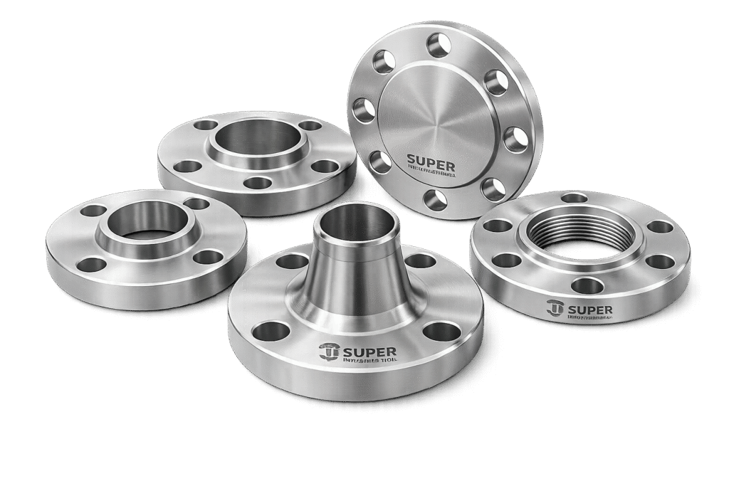
Flanged joints form a fundamental component of engineered piping and pressure systems across capital-intensive industries. Within EPC (Engineering, Procurement, and Construction) environments, flange selection is not a commodity decision—it is a controlled engineering activity governed by pressure integrity, safety compliance, lifecycle performance, and inspection accessibility.
Role of Flanges in Engineered Systems
Flanges are deployed in the following critical system interfaces:
a. Piping Systems
- Provide detachable joints between pipes, valves, and equipment
- Enable maintenance access without system dismantling
- Support modular construction in EPC projects
b. Pressure Vessels
- Used at nozzles, manways, and inspection ports
- Maintain pressure boundary integrity under cyclic loading
c. Rotating Equipment Interfaces
- Connect pumps, compressors, turbines, and heat exchangers
- Allow alignment correction and maintenance isolation
d. High-Pressure / High-Temperature Systems
- Used in steam lines, hydrocarbon processing units, and superheated systems
- Designed to withstand thermal expansion, pressure surges, and fatigue
Industrial Applications
Flanges are critical across:
- Oil & Gas (Upstream / Midstream / Downstream)
Wellheads, pipelines, refineries, petrochemical units - Refineries & Petrochemical Plants
High-temperature and corrosive fluid handling - Power Generation (Thermal / Nuclear / Renewable)
Steam circuits, boiler connections, turbine interfaces - LNG Terminals
Cryogenic service with strict sealing requirements - Chemical Processing Plants
Aggressive media handling and corrosion resistance - Water & Infrastructure Systems
Municipal pipelines, desalination plants - Marine & Offshore Installations
High corrosion exposure and dynamic loading
Why Flanged Joints Over Alternatives
Compared to Welded Joints:
| Parameter | Flanged Joint | Welded Joint |
|---|---|---|
| Maintenance | Detachable | Permanent |
| Inspection | Accessible | Limited |
| Installation | Modular | Fixed |
| Leakage Risk | Depends on gasket | Minimal (if weld integrity maintained) |
| Flexibility | High | Low |
Compared to Threaded Connections:
| Parameter | Flanged Joint | Threaded Joint |
|---|---|---|
| Pressure Capacity | High | Limited |
| Size Range | Large diameters possible | Typically small bore |
| Sealing Integrity | Gasket-based | Thread-based |
| Safety | Suitable for hazardous fluids | Limited in critical systems |
Conclusion:
Flanged joints are preferred in EPC-grade systems where maintainability, inspection access, and pressure integrity are critical.
2. Technical Definition of Flanges
A flange is defined as:
A bolted mechanical joint used to connect piping components, forming a pressure-retaining and detachable interface through controlled gasket compression.
Functional Elements of a Flanged Joint
A complete flange assembly consists of:
a. Flange Body
- Provides structural rigidity
- Transfers load between piping components
b. Flange Faces
Defines sealing interface geometry:
- Raised Face (RF):
Most common; concentrates gasket load - Flat Face (FF):
Used with cast iron or low-pressure systems - Ring Type Joint (RTJ):
Metal-to-metal sealing using ring gasket
c. Gasket
- Compressible sealing element
- Materials: graphite, PTFE, spiral wound, metal ring
d. Bolting System
- Stud bolts + nuts
- Generates preload required for sealing
Sealing Mechanism
The sealing principle is based on:
- Bolt preload → compresses gasket
- Gasket deformation → fills surface irregularities
- Internal pressure → attempts to separate flange faces
- Bolt tension → resists separation
Equilibrium Condition:
Sealing stress ≥ Internal pressure-induced separation force
Super Industries
Global Manufacturer of Heavy & Custom Engineered Fasteners & Flanges
3. TYPES OF FLANGES (Engineering Classification)
The classification of Types of Flanges is based on:
- Connection method
- Pressure capability
- Stress distribution
- Installation requirements
- Maintenance considerations
A. Weld Neck Flange (WN)
Design Characteristics:
- Long tapered hub
- Butt-welded to pipe
- Bore matches pipe ID
Engineering Behavior:
- Provides smooth stress transition
- Minimizes stress concentration
- Suitable for cyclic loading
Applications:
- High-pressure systems
- High-temperature service
- Critical pipelines (oil, steam, gas)
Advantages:
- Superior structural integrity
- Reduced fatigue failure risk
- Full penetration weld
Limitations:
- Higher cost
- Requires skilled welding
B. Slip-On Flange (SO)
Design Characteristics:
- Pipe inserted into flange bore
- Fillet weld on both sides
Engineering Behavior:
- Lower strength than WN
- Double weld improves holding capacity
Applications:
- Low to moderate pressure systems
- Utility lines (water, air)
Advantages:
- Easy alignment
- Lower fabrication cost
Limitations:
- Reduced fatigue resistance
- Not suitable for high-pressure service
C. Socket Weld Flange (SW)
Design Characteristics:
- Socket recess for pipe insertion
- Single fillet weld
Engineering Behavior:
- Good for small bore (≤ 2” / DN50)
- Prevents leakage through bore
Applications:
- High-pressure small diameter lines
- Hydraulic and steam systems
Advantages:
- Strong joint
- Good alignment
Limitations:
- Crevice formation risk
- Not ideal for corrosive fluids
D. Threaded Flange (TH)
Design Characteristics:
- Internal threads
- No welding required
Engineering Behavior:
- Mechanical connection
- Limited pressure capability
Applications:
- Hazardous environments (no welding allowed)
- Low-pressure piping
Advantages:
- No heat input
- Easy installation
Limitations:
- Leak risk under vibration
- Not suitable for cyclic loads
E. Blind Flange (BL)
Design Characteristics:
- Solid disc
- No bore
Engineering Behavior:
- Withstands full system pressure
- Acts as pressure boundary
Applications:
- Pipeline termination
- Pressure testing
- Future expansion points
Advantages:
- High load-bearing capacity
- Simple design
Limitations:
- Heavy in large sizes
- Requires proper bolting
F. Lap Joint Flange (LJ)
Design Characteristics:
- Used with stub end
- Loose backing flange
Engineering Behavior:
- Allows rotation
- Reduces alignment issues
Applications:
- Systems requiring frequent dismantling
- Corrosive services (with alloy stub ends)
Advantages:
- Cost-effective for expensive materials
- Easy alignment
Limitations:
- Lower rigidity
- Not for high-pressure systems
G. Ring Type Joint Flange (RTJ)
Design Characteristics:
- Grooved face
- Metal ring gasket
Engineering Behavior:
- Metal-to-metal sealing
- High sealing integrity
Applications:
- High-pressure systems
- Oil & gas (API service)
Advantages:
- Leak-proof under extreme pressure
- Suitable for high temperature
Limitations:
- Precision machining required
- Higher cost
H. Orifice Flange
Design Characteristics:
- Pressure tapping points
- Designed for flow measurement
Engineering Behavior:
- Integrates with orifice plate
- Measures differential pressure
Applications:
- Flow metering systems
Advantages:
- Integrated design
- Accurate measurement
Limitations:
- Complex installation
- Requires calibration
I. Spectacle Blind / Spacer
Design Characteristics:
- Combination of blind and spacer
- Rotatable element
Engineering Behavior:
- Enables isolation without removal
Applications:
- Maintenance isolation
- Shutdown operations
Advantages:
- Safety during maintenance
- Quick switching
Limitations:
- Requires space for rotation
- Manual handling required
Engineering Summary of Types of Flanges
| Flange Type | Connection Method | Pressure Capability | Typical Use |
|---|---|---|---|
| Weld Neck | Butt weld | Very High | Critical systems |
| Slip-On | Fillet weld | Moderate | Utility piping |
| Socket Weld | Socket + fillet | High (small bore) | Hydraulic systems |
| Threaded | Threaded | Low | Hazardous zones |
| Blind | Bolted | Full pressure | Termination |
| Lap Joint | Stub end | Low–Moderate | Corrosive service |
| RTJ | Metal seal | Very High | Oil & gas |
| Orifice | Bolted | Moderate | Flow measurement |
| Spectacle Blind | Mechanical | System dependent | Isolation |
4. Material & Grade Selection for Flanges
Material selection for Types of Flanges is governed by:
- Design pressure and temperature
- Corrosion environment
- Fluid characteristics (hydrocarbon, steam, chemical, cryogenic)
- Applicable design codes (ASME, EN, API)
- Weldability and fabrication requirements
The selected material must ensure mechanical strength, corrosion resistance, and long-term service reliability under operating conditions.
Carbon Steel Flanges
Carbon steel is widely used due to its strength, cost efficiency, and availability.
Common Grades:
- ASTM A105
- Forged carbon steel for ambient and high-temperature service
- Used in oil & gas, refineries, and power plants
- ASTM A350 LF2
- Designed for low-temperature service
- Improved notch toughness (Charpy impact tested)
Engineering Characteristics:
- Good machinability
- Moderate corrosion resistance (requires coating)
- High strength under pressure
Typical Applications:
- Hydrocarbon pipelines
- Steam systems
- Structural piping
Stainless Steel Flanges
Used where corrosion resistance is critical.
Common Grades:
- ASTM A182 F304
- General-purpose stainless steel
- Suitable for mild corrosive environments
- ASTM A182 F316
- Contains molybdenum for enhanced corrosion resistance
- Suitable for chloride environments
Engineering Characteristics:
- Excellent corrosion resistance
- Good weldability
- Lower strength than alloy steel at high temperature
Applications:
- Chemical processing
- Food-grade systems
- Marine and offshore piping
Alloy Steel Flanges
Used for high-temperature and high-pressure service.
Common Grades:
- ASTM A182 F11
- ASTM A182 F22
Engineering Characteristics:
- High creep strength
- Excellent performance under thermal stress
- Suitable for elevated temperatures
Applications:
- Power plants (boilers, turbines)
- Petrochemical processing
- High-temperature pipelines
Duplex & Super Duplex Stainless Steel
Used in aggressive corrosion environments.
Engineering Characteristics:
- Dual-phase microstructure (austenitic + ferritic)
- High strength (approximately 2× austenitic stainless steel)
- Superior resistance to:
- Chloride stress corrosion cracking
- Pitting and crevice corrosion
Applications:
- Offshore platforms
- Subsea pipelines
- Desalination plants
Material Comparison Table
| Material Grade | Yield Strength (MPa) | Tensile Strength (MPa) | Temperature Range | Corrosion Resistance | Typical Use |
|---|---|---|---|---|---|
| ASTM A105 | ~250 | 485–620 | -29°C to 425°C | Low | Oil & gas piping |
| ASTM A350 LF2 | ~250 | 485–620 | -46°C to 345°C | Low–Moderate | Low-temp service |
| ASTM A182 F304 | ~205 | 515–720 | -196°C to 870°C | Good | General chemical |
| ASTM A182 F316 | ~205 | 515–720 | -196°C to 870°C | Excellent | Marine/chemical |
| ASTM A182 F11 | ~275 | 415–585 | Up to 540°C | Moderate | Power plants |
| ASTM A182 F22 | ~415 | 585–760 | Up to 600°C | Moderate | High-temp service |
| Duplex SS | ~450 | 620–880 | -50°C to 300°C | Very High | Offshore |
| Super Duplex SS | ~550 | 750–950 | -50°C to 300°C | ممتاز | Subsea / marine |
5. Applicable Standards for Types of Flanges
Flanges are governed by international standards that define:
- Dimensions
- Pressure ratings
- Material specifications
- Testing and inspection
ASME Standards
ASME B16.5
- Covers flanges up to NPS 24 (DN600)
- Pressure classes: 150 to 2500
- Defines:
- Dimensions
- Facing types
- Tolerances
ASME B16.47
- Covers large diameter flanges (NPS 26–60)
- Series A (MSS SP-44) and Series B (API 605)
ASTM Material Standards
ASTM defines material composition and mechanical properties:
- ASTM A105 – Carbon steel forgings
- ASTM A182 – Alloy and stainless steel
- ASTM A350 – Low-temperature carbon steel
DIN / EN Standards
Used in European projects:
- DIN 2527 – Blind flanges
- EN 1092-1 – Steel flanges
Pressure ratings defined in PN (Pressure Nominal):
- PN6, PN10, PN16, PN25, PN40, PN63, PN100
ISO Standards
- ISO 7005 – Metal flanges
- Harmonization across international projects
Standards Mapping (Engineering View)
| Standard | Region | Pressure System | Application |
|---|---|---|---|
| ASME B16.5 | USA / Global | Class 150–2500 | Oil & gas, EPC |
| ASME B16.47 | USA | Large diameter | Pipelines |
| ASTM | Global | Material spec | All industries |
| EN 1092-1 | Europe | PN ratings | EU projects |
| DIN | Germany | PN ratings | Industrial |
| ISO | Global | Unified | Cross-border EPC |
6. Heat Treatment of Flanges
Heat treatment is mandatory to achieve required mechanical properties, grain structure, and toughness.
Normalizing
- Heating above transformation temperature and air cooling
- Refines grain structure
- Improves uniformity
Used for: Carbon steel flanges
Quenching & Tempering (Q&T)
- Rapid cooling followed by reheating
- Enhances strength and toughness
Used for: Alloy steel (F11, F22)
Solution Annealing
- Heating followed by rapid cooling
- Dissolves carbides
Used for: Stainless steel
Stress Relieving
- Reduces residual stresses from machining and welding
Heat Treatment Control Parameters
- Temperature uniformity
- Holding time
- Cooling rate
- Hardness limits
Impact Testing (Charpy V-Notch)
- Conducted for low-temperature service
- Ensures fracture toughness
7. Manufacturing Process of Flanges
Manufacturing of Types of Flanges follows controlled, traceable steps to ensure compliance with EPC and inspection standards.
Raw Material Inspection
- Verification of mill test certificates
- Chemical composition analysis
- Positive Material Identification (PMI)
Forging / Rolling
- Open-die or closed-die forging
- Grain flow aligned with stress direction
- Eliminates internal defects
Rough Machining
- Turning of OD/ID
- Bore preparation
CNC Machining
- Precision machining of:
- Flange faces
- Bolt holes
- Groove profiles (RTJ)
Facing Operations
- RF, FF, RTJ machining
- Surface finish control
Drilling
- Bolt hole drilling
- Controlled pitch circle diameter (PCD)
Heat Treatment
- Applied as per material grade
Surface Coating
- Anti-corrosion treatment
Inspection & Testing
- Dimensional checks
- NDT (covered in Part 3)
Marking & Traceability
Each flange marked with:
- Material grade
- Heat number
- Size and rating
- Manufacturer identification
Surface Finish & Coating
Surface condition directly impacts sealing performance and corrosion resistance.
Surface Finish Types
- Stock Finish (Ra 3.2–6.3 µm)
- Smooth Finish (Ra < 3.2 µm)
- Serrated Finish (for gasket grip)
Coating Options
| Coating Type | Purpose | Application |
|---|---|---|
| Phosphate | Temporary corrosion protection | Carbon steel |
| Hot Dip Galvanizing | Long-term corrosion resistance | Water systems |
| PTFE Coating | Chemical resistance | Chemical plants |
| Black Oxide | Mild protection | Indoor use |
| Passivation | Removes free iron | Stainless steel |
Surface Roughness & Sealing
- Higher roughness → better gasket grip
- Excess roughness → leakage risk
- Controlled Ra required per gasket type
Engineering Integration of Materials with Types of Flanges
Material selection must align with flange type:
| Flange Type | Preferred Material | Reason |
|---|---|---|
| Weld Neck | Alloy steel / CS | High stress handling |
| Slip-On | Carbon steel | Cost-effective |
| Socket Weld | Stainless steel | Small bore corrosion resistance |
| Threaded | Carbon steel | Low pressure |
| Blind | Alloy steel | Pressure retention |
| RTJ | Alloy / Duplex | High sealing integrity |
8. Engineering Basis for Selection of Types of Flanges
Selection of Types of Flanges in EPC systems is governed by:
- Internal design pressure
- Operating temperature
- Fluid characteristics
- Piping stress analysis results
- Installation constraints
- Inspection and maintenance requirements
Improper selection leads to:
- Leakage
- Bolt failure
- Gasket blowout
- System shutdown
A. Flange Type Selection Table
| Flange Type | Pressure Range | Temperature Range | Application | Advantages | Limitations |
|---|---|---|---|---|---|
| Weld Neck (WN) | Up to Class 2500 | Up to 600°C+ | Critical pipelines | High strength, fatigue resistant | High cost |
| Slip-On (SO) | Up to Class 600 | Up to 400°C | Utility piping | Easy installation | Lower strength |
| Socket Weld (SW) | Up to Class 1500 | Up to 500°C | Small bore high pressure | Good sealing | Crevice corrosion |
| Threaded (TH) | Low pressure | < 300°C | Hazardous zones | No welding | Leak risk |
| Blind (BL) | Full system pressure | System dependent | Isolation/testing | Strong | Heavy |
| Lap Joint (LJ) | Low–Moderate | < 400°C | Corrosive systems | Alignment flexibility | Low rigidity |
| RTJ | Very High | Up to 650°C | Oil & gas | Metal seal | Cost |
| Orifice | Moderate | System dependent | Flow measurement | Integrated taps | Complex |
| Spectacle Blind | System dependent | System dependent | Isolation | Safe switching | Handling required |
B. Pressure Rating Table (ASME Class vs PSI vs MPa)
| Class | Pressure (PSI) @ 38°C | Pressure (MPa) |
|---|---|---|
| 150 | 285 PSI | 1.96 MPa |
| 300 | 740 PSI | 5.10 MPa |
| 600 | 1480 PSI | 10.20 MPa |
| 900 | 2220 PSI | 15.30 MPa |
| 1500 | 3705 PSI | 25.55 MPa |
| 2500 | 6170 PSI | 42.55 MPa |
Note:
Pressure rating decreases with temperature as per ASME B16.5.
9. Bolt Torque & Tightening Engineering
Proper bolt tightening is critical to ensure:
- Gasket compression
- Leak prevention
- Uniform load distribution
C. Torque Chart
Indicative Torque Values (Carbon Steel Bolts – ASTM A193 B7)
| Bolt Size | Torque (Nm) – Dry | Torque (Nm) – Lubricated |
|---|---|---|
| M16 | 210 | 160 |
| M20 | 410 | 310 |
| M24 | 710 | 530 |
| M27 | 1050 | 780 |
| M30 | 1420 | 1060 |
| M36 | 2500 | 1850 |
Engineering Note:
- Lubrication reduces friction → increases preload at lower torque
- Torque values must be validated against gasket type and flange class
Bolt Tightening Sequence
- Use cross-pattern tightening
- Apply torque in incremental steps (30% → 60% → 100%)
- Final pass ensures uniform stress distribution
Bolt Preload & Sealing Calculations
Correct preload ensures sealing integrity under internal pressure.
Bolt Preload Calculation Guide
1. Bolt Stress Formula

Where:
- σ = Bolt stress (MPa)
- F = Axial force (N)
- A = Bolt cross-sectional area (mm²)
2. Preload Equation

Where:
- F = Preload force
- T = Applied torque
- K = Torque coefficient (~0.18–0.25)
- d = Bolt diameter
3. Axial Separation Force

Where:
- Fₚ = Pressure force
- P = Internal pressure
- A_g = Gasket area
Sample Engineering Calculation
Given:
- Pressure = 5 MPa
- Gasket area = 5000 mm²
Separation Force:
- Fₚ = 5 × 5000 = 25,000 N
Design Requirement:
- Bolt preload must exceed separation force with safety factor
Safety Factor Philosophy
- Typical safety factor: 2 to 3
- Accounts for:
- Relaxation
- Temperature effects
- Dynamic loads
Mechanical Property Table
| Material | Yield Strength (MPa) | Tensile Strength (MPa) | Elongation (%) | Hardness (HB) |
|---|---|---|---|---|
| ASTM A105 | 250 | 485–620 | 22 | 120–180 |
| ASTM A182 F304 | 205 | 515–720 | 30 | 140–200 |
| ASTM A182 F316 | 205 | 515–720 | 30 | 140–200 |
| ASTM A182 F11 | 275 | 415–585 | 20 | 130–200 |
| ASTM A182 F22 | 415 | 585–760 | 18 | 150–220 |
| Duplex SS | 450 | 620–880 | 25 | 200–300 |
Corrosion Resistance Comparison
| Material | Marine | Acidic | Hydrocarbon | Chloride Resistance |
|---|---|---|---|---|
| Carbon Steel | Poor | Poor | Good | Poor |
| SS304 | Moderate | Moderate | Good | Moderate |
| SS316 | Good | Good | Good | Good |
| Alloy Steel | Moderate | Moderate | Excellent | Moderate |
| Duplex SS | Excellent | Good | Excellent | Excellent |
10. Inspection & Quality Control
Inspection of Types of Flanges is mandatory to ensure compliance with EPC specifications and international standards.
Dimensional Inspection
- Outer diameter (OD)
- Inner diameter (ID)
- Bolt circle diameter (BCD/PCD)
- Thickness
- Facing dimensions
Non-Destructive Testing (NDT)
a. PMI (Positive Material Identification)
- Confirms material composition
b. UT (Ultrasonic Testing)
- Detects internal defects
c. MPI (Magnetic Particle Inspection)
- Surface/subsurface cracks in ferromagnetic materials
d. DPI (Dye Penetrant Inspection)
- Surface crack detection
Hydrostatic Testing
- Applied to validate pressure integrity
- Typically performed on assembled systems
Hardness Testing
- Ensures compliance with material specifications
- Prevents brittle failure
Visual Inspection
- Surface defects
- Machining quality
- Marking verification
Certification Requirements
- EN 10204 3.1 Certification
- Manufacturer test certificate
- EN 10204 3.2 Certification
- Third-party verified
Third-Party Inspection
Conducted by:
- Independent inspection agencies
- Client-appointed inspectors
- EPC consultants
Includes:
- Stage inspection
- Final inspection
- Documentation verification
Integration of Engineering Controls
To ensure performance of Types of Flanges, the following must be aligned:
- Correct flange selection
- Verified material grade
- Proper torque application
- Accurate machining tolerances
- Controlled gasket compression
- Certified inspection procedures
11. Procurement Engineering Perspective for Types of Flanges
In EPC execution, procurement of Types of Flanges is governed by technical compliance rather than commercial prioritization. Flanges form part of the pressure boundary and are therefore subject to strict evaluation criteria.
Technical Evaluation Parameters
Procurement teams and consultants evaluate flange supply based on:
a. Standards Compliance
- ASME B16.5 / B16.47 dimensional conformity
- Material compliance with ASTM specifications
- Pressure-temperature rating validation
b. Material Traceability
- Heat number traceability from raw material to finished product
- Mill Test Certificates (MTC) verification
c. Manufacturing Capability
- Forging capacity (size and weight range)
- CNC machining precision
- Heat treatment facilities
d. Inspection Readiness
- Availability of NDT procedures
- Third-party inspection acceptance
- Documentation completeness
Documentation Requirements
Typical EPC documentation package includes:
- Material Test Certificates (EN 10204 3.1 / 3.2)
- Dimensional inspection reports
- NDT reports (UT, PMI, MPI, DPI)
- Heat treatment charts
- Calibration certificates
- Manufacturing process records
- Packing list and traceability documentation
Vendor Qualification Criteria
A flange manufacturer is evaluated on:
- Compliance with international standards
- Proven supply to EPC contractors
- Ability to meet project specifications (datasheets, MR, ITP)
- Audit acceptance (client / third-party)
12. Installation Engineering for Flanged Joints
Proper installation of Types of Flanges is essential to achieve designed sealing performance and system reliability.
Pre-Installation Checks
- Verify flange rating, size, and material
- Inspect flange face for damage or contamination
- Confirm gasket type and compatibility
- Ensure bolt and nut grade compliance
Flange Alignment
Misalignment introduces:
- Uneven gasket compression
- Bolt overstressing
- Leakage risk
Alignment Requirements:
- Parallel flange faces
- Concentric bolt holes
- Controlled angular deviation
Gasket Selection
Gasket selection must match:
- Pressure class
- Temperature
- Fluid compatibility
- Flange facing type (RF / FF / RTJ)
Bolt Tightening Procedure
Step-by-Step:
- Insert gasket centrally
- Install bolts and nuts
- Apply initial snug tightening
- Tighten in cross-pattern sequence
- Apply torque in stages:
- 30%
- 60%
- 100%
- Perform final torque verification
Torque Control
- Use calibrated torque wrench or hydraulic tensioner
- Apply lubrication where specified
- Monitor torque consistency
Post-Installation Inspection
- Check bolt elongation (if required)
- Verify gasket compression
- Inspect for visible gaps
- Conduct pressure testing
Storage & Handling Practices
- Protect flange faces with covers
- Store in dry, non-corrosive environment
- Avoid stacking damage
- Maintain identification markings
Custom Engineering Capabilities
For EPC projects, standard dimensions may not always meet system requirements. Customization of Types of Flanges is often required.
Non-Standard Sizes
- Large diameter flanges beyond standard ranges
- Special thickness for high-pressure service
Special Drilling Patterns
- Custom bolt hole configurations
- Matching legacy or non-standard equipment
High-Thickness / Heavy Flanges
- Designed for:
- High-pressure systems
- Critical isolation points
Special Coatings
- PTFE lining for chemical resistance
- Anti-corrosion coatings for offshore use
Project-Specific Marking
- Tag numbers
- Heat numbers
- Client-specific identification
13. Industries Served
Manufacturing and supply of Types of Flanges support the following industries:
Oil & Gas
- Upstream: Wellheads, drilling systems
- Midstream: Pipelines, compressor stations
- Downstream: Refineries, petrochemical plants
Refineries & Petrochemical Plants
- High-temperature and corrosive service
- Process-critical piping systems
Power Generation
- Thermal power plants
- Nuclear facilities
- Steam and turbine systems
LNG & Cryogenic Systems
- Low-temperature service
- Leak-tight sealing requirements
Offshore & Marine
- Exposure to saltwater corrosion
- Dynamic loading conditions
Chemical Processing
- Aggressive fluids
- High corrosion resistance requirements
Infrastructure & Water Systems
- Municipal pipelines
- Desalination plants
14. Export Capability
Supply of Types of Flanges for international EPC projects requires structured export capability.
Global Supply Regions
- United States
- Europe
- Middle East
- Southeast Asia
Packaging Standards
- Wooden crates / pallets
- Moisture protection
- Face protection covers
- Marking as per international shipping norms
Documentation for Export
- Commercial invoice
- Packing list
- Certificate of origin
- Inspection certificates
- Compliance documentation
Logistics Support
- Coordination with freight forwarders
- Handling oversized cargo
- Compliance with import regulations
Integrated Engineering Control Across Lifecycle
For effective application of Types of Flanges, the following lifecycle controls must be maintained:
| Stage | Control Parameter |
|---|---|
| Design | Pressure-temperature rating |
| Material Selection | Corrosion and strength |
| Manufacturing | Forging and machining quality |
| Heat Treatment | Mechanical properties |
| Inspection | NDT and dimensional accuracy |
| Installation | Torque and alignment |
| Operation | Monitoring and maintenance |
Engineering Conclusion
The classification and application of Types of Flanges represent a controlled engineering discipline within pressure system design. Selection is not isolated—it is integrated with:
- Piping stress analysis
- Material engineering
- Pressure containment design
- Installation methodology
- Inspection and certification protocols
A flange is not a standalone component; it is a pressure boundary element whose performance depends on:
- Correct type selection
- Material suitability
- Manufacturing integrity
- Controlled installation
- Verified inspection
Within EPC environments, the evaluation of flange supply is based on:
- Standards compliance
- Engineering documentation
- Manufacturing traceability
- Inspection readiness
This structured approach ensures that flange assemblies perform reliably under:
- High pressure
- Elevated temperature
- Corrosive environments
- Cyclic loading conditions
Final Technical Position
A complete understanding of Types of Flanges must include:
- Mechanical design principles
- Sealing behavior
- Pressure rating systems
- Material science
- Manufacturing processes
- Installation controls
Only when these parameters are aligned can flange systems meet the expectations of:
- EPC contractors
- Design consultants
- Inspection agencies
- End-user operators