
TONGUE GROOVE FLANGES
Super Industries
“Global Manufacturer of Heavy & Custom Engineered Fasteners for Oil & Gas, Power & EPC Contractors.”
1. Industry Context & System Relevance
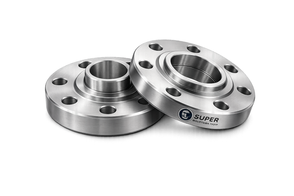
Tongue & Groove Flanges are deployed in pressure-retaining piping systems where controlled gasket confinement and leak-tight sealing integrity are required under demanding operating conditions. Their geometry is specifically engineered to address sealing risks associated with pressure cycling, thermal expansion, and fluid containment sensitivity.
System Role in High-Pressure Sealing
In a bolted flange joint, sealing integrity depends on:
- Gasket compression
- Bolt preload stability
- Flange face geometry
- Resistance to internal pressure-induced separation
Tongue & Groove (T&G) configurations introduce mechanical confinement of gasket material, reducing dependency solely on bolt load and frictional resistance.
Application Domains
T&G flange joints are commonly applied in:
- Oil & Gas Processing Units
- High-pressure separators
- Crude distillation units
- Refineries
- Hydroprocessing systems
- Reforming units
- Petrochemical Plants
- Polymer reactors
- Aromatics processing lines
- Power Generation
- High-pressure steam lines
- Turbine inlet piping
- LNG Terminals
- Cryogenic transfer lines
- Hydrogen Systems
- High-diffusivity gas containment
- Offshore Installations
- Subsea and topside piping requiring leak-proof reliability
Why Tongue & Groove Over Other Facing Types
| Facing Type | Limitation | T&G Advantage |
|---|---|---|
| Raised Face (RF) | Gasket exposed, prone to lateral movement | Confined gasket eliminates displacement |
| Flat Face (FF) | Low-pressure suitability only | T&G supports high-pressure sealing |
| Ring Type Joint (RTJ) | Requires precision ring, higher cost | T&G provides reliable sealing with soft gasket |
| T&G | — | Controlled compression + alignment stability |
Key Engineering Advantages
- Positive gasket confinement
- Reduced risk of blowout
- Improved sealing under vibration
- Better alignment control during assembly
- Consistent sealing stress distribution
2. Technical Definition
Tongue & Groove Flanges are a matched flange pair system designed with complementary sealing geometries:
- Tongue Flange (Male Face):
- Raised annular projection
- Groove Flange (Female Face):
- Precisely machined recessed cavity
Functional Geometry
- The tongue fits into the groove, forming:
- Controlled seating cavity
- Positive alignment interface
- A gasket is enclosed within the groove, preventing displacement
Critical Dimensional Relationships
| Parameter | Engineering Function |
|---|---|
| Tongue Height | Controls penetration into groove |
| Groove Depth | Determines gasket compression volume |
| Groove Width | Defines gasket seating area |
| Clearance Fit | Allows assembly without binding |
Gasket Seating Behavior
- Gasket is fully enclosed radially
- Compression occurs within defined boundaries
- Prevents:
- Radial extrusion
- Misalignment-induced leakage
Metal-to-Metal Contact Control
Proper design ensures:
- Flanges do not fully bottom out prematurely
- Gasket retains primary sealing responsibility
- Contact occurs only when:
- Design compression limit is reached
Alignment Advantages
- Self-centering geometry
- Reduced installation error
- Improved concentricity under bolt tightening
3. Engineering & Sealing Principle
Gasket Confinement Mechanics
Unlike open-face systems, T&G flanges:
- Trap the gasket within the groove
- Restrict lateral deformation
- Maintain consistent contact pressure
This creates a closed sealing chamber, improving reliability.
Controlled Compression Behavior
- Groove depth is slightly greater than gasket thickness
- Compression occurs under bolt preload
- Ensures:
- Uniform stress distribution
- Prevention of over-compression
Blowout Prevention Mechanism
Under internal pressure:
- Gasket experiences radial force
- Groove walls resist lateral displacement
- Eliminates blowout pathways
Reduction of Gasket Movement
In cyclic conditions:
- RF gaskets may shift due to pressure variation
- T&G gaskets remain mechanically locked in position
Bolt Preload Distribution
- Load transferred through:
- Flange faces
- Gasket interface
- T&G ensures:
- Load is focused on confined gasket zone
- Reduced uneven stress zones
Sealing Stress Concentration
- Stress localized within groove
- Leads to:
- Higher effective sealing pressure
- Lower required bolt load compared to RF
Groove Depth vs Gasket Thickness
Engineering requirement:
- Groove depth = gasket thickness + clearance
- Clearance ensures:
- Controlled compression
- No crushing of gasket
Flange Face Finish Influence
Surface roughness (Ra):
- Too smooth → gasket slip
- Too rough → leakage paths
Typical requirement:
- 3.2 – 6.3 µm Ra for optimal sealing
Leakage Prevention Under Pressure Cycling
T&G flanges perform under:
- Pressure fluctuations
- Thermal expansion cycles
- Mechanical vibration
Due to:
- Confined gasket geometry
- Stable compression profile
High-Temperature Sealing Behavior
At elevated temperatures:
- Gasket softening occurs
- Bolt preload reduces (creep relaxation)
T&G design compensates through:
- Mechanical confinement
- Reduced reliance on friction
- Retention of sealing stress
4. Pressure & Load Engineering
Pressure Class Range
Tongue & Groove Flanges are manufactured across:
- ASME Class 150
- Class 300
- Class 600
- Class 900
- Class 1500
- Class 2500
High-Pressure Sealing Performance
Under high pressure:
- Internal force attempts flange separation
- Gasket stress must exceed internal pressure
T&G ensures:
- Stress retention within groove
- Reduced leakage probability
Static vs Cyclic Loads
| Load Type | Effect | T&G Response |
|---|---|---|
| Static | Constant stress | Stable sealing |
| Cyclic | Fluctuating stress | Gasket confinement maintains seal |
Thermal Expansion Impact
Differential expansion between:
- Bolts
- Flanges
- Gasket
Can reduce preload.
T&G design:
- Maintains seal even under reduced preload
- Limits gasket displacement
Bolt Load Retention
Factors affecting preload:
- Creep
- Relaxation
- Thermal cycles
T&G advantage:
- Less dependence on high preload
- Better sealing with moderate bolt stress
Stress Distribution in T&G Geometry
- Tongue experiences compressive stress
- Groove wall experiences radial pressure
- Gasket carries sealing load
Balanced distribution reduces:
- Localized overstress
- Flange deformation
Axial Separation Force Behavior
Internal pressure generates:
- Axial force attempting to separate flanges
T&G counters via:
- Confined gasket resisting movement
- Load redistribution across sealing area
Gasket Stress Retention
Maintained through:
- Mechanical confinement
- Reduced creep effects
- Limited relaxation pathways
Safety Factor Philosophy
Design considers:
- Maximum operating pressure
- Temperature variation
- Bolt preload uncertainty
Typical approach:
- Safety factor applied to:
- Bolt stress
- Gasket stress
- Flange thickness
Failure Modes
| Failure Mode | Cause | Mitigation via T&G |
|---|---|---|
| Gasket Extrusion | High pressure | Groove confinement |
| Flange Distortion | Uneven loading | Controlled geometry |
| Leakage | Loss of preload | Sealing chamber design |
| Surface Damage | Improper machining | Precision finishing |
Dimensional & Design Logic
Key Geometric Parameters
| Parameter | Function |
|---|---|
| Tongue Height | Penetration control |
| Groove Depth | Gasket compression space |
| Groove Width | Seating area |
| Flange Thickness | Structural strength |
| Bolt Circle Diameter | Load distribution |
Tolerance Requirements
Critical tolerances include:
- Groove width tolerance: ±0.05 mm
- Tongue height tolerance: ±0.03 mm
- Concentricity: ≤ 0.1 mm
- Parallelism: ≤ 0.05 mm
Surface Finish Requirements
| Surface | Ra Value |
|---|---|
| Tongue Face | 3.2 – 6.3 µm |
| Groove Base | 3.2 – 6.3 µm |
Raised Face vs T&G Comparison
| Feature | Raised Face | T&G |
|---|---|---|
| Gasket Exposure | Open | Confined |
| Pressure Suitability | Moderate | High |
| Blowout Resistance | Limited | High |
| Alignment | Manual | Self-guided |
Machining Precision Requirements
Critical operations:
- CNC groove cutting
- Tongue concentricity control
- Face flatness
Precision directly affects:
- Gasket seating
- Leakage prevention
- Joint reliability
5. Applicable Standards (ASME / ASTM / DIN / EN / ISO)
Tongue & Groove Flanges are manufactured and evaluated in accordance with internationally recognized pressure equipment and piping standards. Compliance ensures interchangeability, dimensional integrity, and pressure-temperature reliability.
ASME Standards
ASME B16.5
Applies to:
- NPS ½” to 24”
- Pressure Classes: 150 to 2500
Defines:
- Flange dimensions
- Pressure-temperature ratings
- Facing types (including Tongue & Groove)
- Bolt circle dimensions
- Tolerances
Relevance to T&G Flanges:
- Specifies allowable facing configurations
- Governs dimensional envelope for flange geometry
- Ensures compatibility with piping systems
ASME B16.47 (Series A & B)
Applies to:
- NPS 26” to 60”
Defines:
- Large diameter flange dimensions
- Higher load applications
Engineering Impact:
- Larger bolt load requirements
- Increased flange thickness
- Greater machining precision for groove geometry
ASTM Material Standards
Material compliance is governed by ASTM specifications, ensuring:
- Mechanical properties
- Chemical composition
- Heat treatment conditions
Relevant standards include:
- ASTM A105 – Forged carbon steel (ambient/high temp)
- ASTM A350 LF2 – Low temperature carbon steel
- ASTM A182 – Alloy and stainless steel forgings
DIN / EN Standards
EN 1092-1
Defines:
- European flange dimensions
- PN pressure ratings
- Facing configurations
DIN Standards (DIN 2527 / DIN 2633 etc.)
- Applicable in EU and Middle East projects
- Provide dimensional equivalence to ASME systems
ISO Alignment
ISO standards harmonize:
- Dimensional consistency
- Material equivalence
- Global interchangeability
Pressure-Temperature Rating Compliance
Ratings are determined based on:
- Material group
- Temperature range
- ASME pressure class
Engineering Requirement:
Pressure rating must always be derated with temperature increase.
6. Material & Grade Options
Material selection for Tongue & Groove Flanges is governed by:
- Operating pressure
- Temperature
- Corrosive environment
- Fluid composition
Carbon Steel
ASTM A105
- Standard forged carbon steel
- Suitable for:
- Ambient to moderate temperature
- Hydrocarbon service
ASTM A350 LF2
- Low-temperature carbon steel
- Impact tested
- Used in:
- Cryogenic systems
- Sub-zero applications
Stainless Steel
ASTM A182 F304
- General corrosion resistance
- Suitable for:
- Water
- Mild chemicals
ASTM A182 F316
- Enhanced corrosion resistance
- Molybdenum addition
- Suitable for:
- Chlorides
- Marine environments
Duplex & Super Duplex Stainless Steel
- Higher strength than austenitic stainless steel
- Excellent resistance to:
- Chloride stress corrosion cracking
- Pitting corrosion
Applications:
- Offshore systems
- Seawater handling
Alloy Steel
ASTM A182 F11 / F22
- Chromium-Molybdenum steels
- High-temperature strength
- Used in:
- Power plants
- Steam systems
- Refinery heaters
Material Comparison Table
| Material Grade | Yield Strength (MPa) | Tensile Strength (MPa) | Temperature Range (°C) | Corrosion Resistance | Typical Industry Use |
|---|---|---|---|---|---|
| ASTM A105 | ~250 | 485–620 | -29 to 425 | Low | Oil & Gas, General Service |
| ASTM A350 LF2 | ~250 | 485–620 | -46 to 345 | Low | Cryogenic, LNG |
| A182 F304 | ~205 | 515–720 | -196 to 870 | Moderate | Chemical, Water Systems |
| A182 F316 | ~205 | 515–720 | -196 to 870 | High | Marine, Chloride Service |
| Duplex (2205) | ~450 | 620–880 | -50 to 300 | Very High | Offshore, Seawater |
| F11 | ~275 | 415–585 | Up to 540 | Moderate | Power, Refinery |
| F22 | ~415 | 585–760 | Up to 600 | Moderate | High-temp Steam Systems |
Material Selection Considerations
| Condition | Recommended Material |
|---|---|
| High Pressure + Moderate Temp | A105 |
| Low Temperature | A350 LF2 |
| Corrosive Fluids | F316 / Duplex |
| High Temperature | F11 / F22 |
| Marine Exposure | Duplex |
7. Heat Treatment Information
Heat treatment is critical to ensure:
- Mechanical strength
- Structural stability
- Resistance to cracking
- Sealing surface integrity
Normalizing
- Applied to carbon steel
- Refines grain structure
- Improves:
- Strength uniformity
- Machinability
Quenching & Tempering (Q&T)
Applicable to:
- Alloy steels (F11, F22)
Process:
- Heating above critical temperature
- Rapid cooling (quenching)
- Controlled reheating (tempering)
Effect:
- Increased toughness
- Improved strength
- Reduced brittleness
Solution Annealing
Used for:
- Stainless steels (F304, F316)
Process:
- Heating to high temperature
- Rapid cooling
Effect:
- Restores corrosion resistance
- Eliminates carbide precipitation
Stress Relieving
- Reduces residual stresses from forging/machining
- Prevents:
- Distortion
- Cracking under load
Hardness Control
Typical hardness ranges:
| Material | Hardness (HB) |
|---|---|
| A105 | 137–187 |
| LF2 | 120–200 |
| F316 | ≤ 200 |
| F22 | 150–220 |
Microstructure Impact
Heat treatment influences:
- Grain size
- Phase distribution
- Crack propagation resistance
This directly affects:
- Flange strength
- Sealing face stability
Charpy V-Notch Impact Testing
Mandatory for:
- Low-temperature service
- Critical pressure applications
Measures:
- Material toughness
- Resistance to brittle fracture
8. Manufacturing Process
Manufacturing of Tongue & Groove Flanges requires controlled forging and high-precision machining.
Step-by-Step Process Flow
1. Raw Material Inspection
- Chemical composition verification
- Mill test certificate validation
- PMI (Positive Material Identification)
2. Forging
- Open-die or closed-die forging
- Ensures:
- Grain flow alignment
- Mechanical strength
3. Rough Machining
- Removal of excess material
- Preparation for precision machining
4. CNC Machining of Tongue & Groove
Critical stage:
- Groove depth accuracy
- Tongue height precision
- Concentric alignment
Tolerance control is essential for:
- Gasket seating
- Sealing integrity
5. Bolt Hole Drilling
- CNC drilling for accuracy
- Ensures:
- Proper alignment
- Uniform load distribution
6. Surface Finishing
- Facing operations
- Achieving required Ra values
7. Heat Treatment
- As per material specification
- Conducted before final finishing (if required)
8. Coating / Surface Protection
- Applied based on service condition
9. Final Inspection
Includes:
- Dimensional verification
- Surface finish inspection
- NDT testing
10. Marking & Traceability
Marking includes:
- Material grade
- Heat number
- Size and pressure class
- Manufacturer identification
Ensures:
- Full traceability
- Compliance with EPC documentation
Surface Finish Options
Surface condition affects both:
- Corrosion resistance
- Gasket sealing performance
Common Surface Treatments
| Finish Type | Application |
|---|---|
| Phosphate Coating | Corrosion resistance (carbon steel) |
| Zinc Plating | Mild corrosion protection |
| Hot-Dip Galvanizing | Outdoor/marine environments |
| PTFE Coating | Chemical resistance |
| Black Oxide | Temporary protection |
| Passivation (SS) | Enhances corrosion resistance |
Surface Roughness (Ra) Requirements
| Surface | Ra Value |
|---|---|
| Sealing Faces | 3.2 – 6.3 µm |
| Non-sealing Areas | ≤ 12.5 µm |
Impact on Gasket Performance
| Condition | Effect |
|---|---|
| Smooth Surface | Risk of gasket slip |
| Rough Surface | Potential leakage paths |
| Controlled Ra | Optimal sealing |
Critical Engineering Requirement
For Tongue & Groove Flanges:
- Groove base finish must be controlled
- Tongue face must maintain uniform texture
- No machining marks across sealing direction
A. Technical Dimension Tables (Representative Engineering Data)
Dimensional values for Tongue & Groove Flanges are governed by ASME B16.5 / B16.47, with additional constraints for groove geometry to ensure gasket confinement.
Note: Final dimensions must always be verified against the applicable standard revision and project specification.
Table A1: Tongue & Groove Flange Dimensions (Indicative)
| Nominal Size (NPS) | Pressure Class | Tongue Height (mm) | Groove Depth (mm) | Groove Width (mm) | Bolt Size | Bolt Circle Diameter (mm) |
|---|---|---|---|---|---|---|
| 1” | 150 | 3.2 | 3.5 | 6.5 | M12 | 79 |
| 2” | 300 | 3.5 | 3.8 | 7.0 | M16 | 102 |
| 4” | 600 | 4.0 | 4.3 | 8.0 | M20 | 191 |
| 6” | 900 | 4.5 | 4.8 | 9.0 | M24 | 279 |
| 8” | 1500 | 5.0 | 5.4 | 10.0 | M27 | 356 |
| 10” | 2500 | 5.5 | 6.0 | 11.0 | M30 | 432 |
Engineering Interpretation
- Groove depth is typically 0.2–0.5 mm greater than gasket thickness
- Tongue height ensures positive engagement without bottoming
- Groove width defines effective sealing area
B. Pressure Rating Table (ASME Class vs Temperature)
Pressure-temperature ratings depend on:
- Material group
- ASME classification
- Operating temperature
Table B1: Pressure Rating (Carbon Steel – ASTM A105)
| Temperature (°C) | Class 150 (bar) | Class 300 (bar) | Class 600 (bar) | Class 900 (bar) | Class 1500 (bar) | Class 2500 (bar) |
|---|---|---|---|---|---|---|
| 38 | 19.6 | 51.1 | 102.1 | 153.2 | 255.3 | 425.5 |
| 100 | 17.5 | 45.5 | 91.0 | 136.5 | 227.5 | 379.0 |
| 200 | 15.0 | 39.0 | 78.0 | 117.0 | 195.0 | 325.0 |
| 300 | 13.0 | 33.8 | 67.6 | 101.4 | 169.0 | 282.0 |
| 400 | 10.2 | 26.5 | 53.0 | 79.5 | 132.5 | 221.0 |
Engineering Notes
- Pressure capacity decreases with temperature
- Ratings must be derated for elevated temperatures
- T&G geometry maintains sealing even near upper limits
C. Torque Chart
Bolt tightening torque is critical for achieving required gasket seating stress.
Table C1: Recommended Bolt Torque (Indicative Values)
| Bolt Size | Material Grade | Lubricated Torque (Nm) | Dry Torque (Nm) |
|---|---|---|---|
| M12 | Class 8.8 | 70 | 95 |
| M16 | Class 8.8 | 170 | 230 |
| M20 | Class 8.8 | 330 | 450 |
| M24 | Class 8.8 | 570 | 770 |
| M27 | Class 10.9 | 900 | 1200 |
| M30 | B7 | 1300 | 1750 |
| M36 | B7 | 2300 | 3100 |
Torque Application Guidelines
- Apply torque in incremental steps (30% → 60% → 100%)
- Use cross-pattern tightening
- Re-torque after:
- Initial pressurization
- Thermal stabilization
D. Preload Calculation Guide
Proper preload ensures:
- Gasket seating stress > internal pressure
- Joint integrity under operating conditions
1. Bolt Stress Formula

Where:
- ( \sigma_b ) = Bolt stress
- ( F_b ) = Bolt force
- ( A_b ) = Bolt stress area
2. Preload Force Equation

Where:
- ( F ) = Internal separating force
- ( P ) = Internal pressure
- ( A ) = Effective sealing area
3. Gasket Seating Requirement
Condition for safe sealing:

4. Axial Separation Force
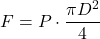
Where:
- ( D ) = Effective gasket diameter
5. Sample Engineering Calculation
Given:
- Pressure ( P = 50 , bar = 5 , MPa )
- Gasket diameter ( D = 200 , mm )
Step 1: Area Calculation

Step 2: Internal Force

Step 3: Required Bolt Load

Engineering Insight
- T&G flanges require lower additional safety margin compared to RF due to gasket confinement
- Load distribution is more efficient
E. Yield Strength Chart (Engineering Explanation)
Yield strength determines:
- Maximum allowable stress before plastic deformation
Typical Observations
- Carbon steel (A105): moderate yield, suitable for general service
- Stainless steel: lower yield but higher ductility
- Duplex: high yield, suitable for compact high-pressure design
- Alloy steel (F22): high-temperature strength retention
Engineering Impact
Higher yield strength enables:
- Reduced flange thickness
- Higher pressure capability
- Improved structural reliability
F. Mechanical Property Table
| Material | Yield Strength (MPa) | Tensile Strength (MPa) | Elongation (%) | Hardness (HB) | Impact Toughness |
|---|---|---|---|---|---|
| A105 | 250 | 485–620 | 22 | 137–187 | Moderate |
| LF2 | 250 | 485–620 | 20 | 120–200 | High (low temp) |
| F304 | 205 | 515–720 | 30 | ≤ 200 | High |
| F316 | 205 | 515–720 | 30 | ≤ 200 | High |
| Duplex | 450 | 620–880 | 25 | 250–300 | High |
| F22 | 415 | 585–760 | 20 | 150–220 | Moderate |
G. Corrosion Resistance Comparison Table
| Material | Marine | Acidic | Hydrocarbon | High Humidity |
|---|---|---|---|---|
| Carbon Steel | Poor | Poor | Good | Poor |
| SS304 | Moderate | Moderate | Good | Good |
| SS316 | High | High | Good | High |
| Duplex | Very High | High | Excellent | Very High |
| Alloy Steel | Moderate | Low | Excellent | Moderate |
9. Inspection & Quality Control Methods
Inspection of Tongue & Groove Flanges focuses on:
- Material integrity
- Dimensional precision
- Surface quality
- Defect detection
1. PMI (Positive Material Identification)
- Verifies alloy composition
- Ensures correct material grade
2. Ultrasonic Testing (UT)
- Detects internal defects
- Ensures forging integrity
3. Magnetic Particle Inspection (MPI)
- Surface/subsurface crack detection
- Applicable to ferromagnetic materials
4. Dye Penetrant Inspection (DPI)
- Surface crack detection
- Used for stainless steel and non-magnetic materials
5. Dimensional Inspection (Critical for T&G)
Measured parameters:
- Groove depth and width
- Tongue height
- Concentricity
- Flatness
- Bolt hole alignment
Tolerance verification is essential for:
- Gasket seating
- Leak prevention
6. Hardness Testing
- Confirms heat treatment effectiveness
- Prevents brittle or over-soft conditions
7. Surface Finish Verification
- Profilometer measurement (Ra value)
- Ensures sealing surface compliance
8. Third-Party Inspection (TPI)
Conducted by:
- Independent inspection agencies
Covers:
- Material traceability
- Dimensional checks
- NDT validation
9. Certification
- EN 10204 3.1
- Manufacturer test certificate
- EN 10204 3.2
- Third-party validated certification
Inspection Outcome Objective
Ensure that:
- Flange geometry matches design intent
- Sealing surfaces meet required finish
- Material properties align with standards
- Product is ready for EPC project deployment
10. Industries Served
Tongue & Groove Flanges are deployed in sectors where leak containment, pressure integrity, and sealing reliability are critical to system safety and operational continuity.
Oil & Gas (Upstream & Downstream)
Applications include:
- Wellhead flowlines
- High-pressure separators
- Gas compression stations
- Crude and refined product transfer systems
Engineering Requirement:
- Resistance to pressure cycling
- Hydrocarbon compatibility
- Leak-proof sealing under fluctuating loads
T&G configuration is selected where:
- Gasket displacement risk must be minimized
- Maintenance intervals are extended
Refineries
Typical service locations:
- Distillation columns
- Hydrocrackers
- Catalytic reforming units
Operating Conditions:
- Elevated temperature
- High pressure
- Corrosive hydrocarbons
T&G flanges ensure:
- Stable sealing under thermal cycling
- Reduced gasket degradation risk
Petrochemical Plants
Used in:
- Polymer processing lines
- Aromatics and solvent systems
- Chemical reactors
Engineering Consideration:
- Chemical compatibility of gasket and flange material
- Prevention of fugitive emissions
Power Plants
Applications include:
- Main steam lines
- Boiler feedwater systems
- Turbine inlet piping
Material Selection:
- Alloy steels (F11, F22) for high-temperature strength
T&G advantages:
- Maintains sealing integrity under thermal expansion
- Reduces leak risk in critical steam circuits
LNG & Cryogenic Systems
Used in:
- LNG transfer lines
- Storage tank piping
- Regasification units
Material Requirement:
- Low-temperature toughness (ASTM A350 LF2, stainless steel)
T&G design ensures:
- Gasket stability at sub-zero temperatures
- Prevention of brittle failure leakage
Hydrogen Systems
Emerging application domain with strict requirements:
- High diffusivity containment
- Leak-tight sealing
T&G flanges provide:
- Reduced permeation leakage paths
- Enhanced sealing consistency
Offshore Platforms
Applications:
- Subsea manifolds
- Topside processing units
- Seawater handling systems
Environmental Challenges:
- High humidity
- Salt exposure
- Dynamic loading
Material preference:
- Duplex stainless steel
11. Export Capability & Global Supply
Super Industries operates as a manufacturer with export capability aligned to EPC project requirements.
Regions Served
- United States
- European Union
- Middle East (UAE, Saudi Arabia, Qatar, Oman)
- Southeast Asia
Export Packaging
Packaging is structured to prevent:
- Mechanical damage
- Corrosion during transit
- Surface contamination of sealing faces
Methods include:
- Wooden export crates (ISPM-15 compliant)
- Anti-corrosion wrapping (VCI)
- Face protection covers for T&G surfaces
Documentation Package
Each shipment is supported by:
- Commercial invoice
- Packing list
- Mill test certificates (EN 10204 3.1 / 3.2)
- Inspection reports (NDT, dimensional)
- Heat treatment charts
- Material traceability records
Project Logistics Capability
Supports:
- Bulk project supply
- Mixed size/class shipments
- Lot traceability for EPC projects
- Coordination with third-party inspection agencies
12. PROCUREMENT & INSTALLATION VIEW
Procurement Considerations
When sourcing Tongue & Groove Flanges, EPC and engineering teams must verify:
1. Correct Flange Pairing
- One tongue flange (male)
- One groove flange (female)
Mismatch Risk:
- Improper sealing
- Assembly failure
2. Dimensional Compliance
- Verify against ASME / EN standards
- Confirm groove geometry tolerances
Critical checks:
- Groove depth
- Tongue height
- Concentricity
3. Material Certification
- ASTM compliance
- Heat number traceability
- PMI validation
4. Surface Finish Verification
- Ra value within specified limits
- No machining marks across sealing direction
5. Gasket Compatibility
Gasket must:
- Fit within groove dimensions
- Match operating temperature and fluid
Installation Guidelines
Correct installation is essential to achieve design sealing performance.
1. Pre-Assembly Inspection
Check:
- Cleanliness of groove and tongue
- Absence of damage or dents
- Proper gasket dimensions
2. Gasket Placement
- Insert gasket fully within groove
- Ensure no twisting or misalignment
3. Flange Alignment
- Ensure tongue enters groove without force
- Avoid angular misalignment
4. Bolt Tightening Sequence
Use cross-pattern tightening:
- Initial snug tightening
- 30% torque
- 60% torque
- 100% final torque
5. Torque Control
- Use calibrated torque wrench
- Apply lubrication where specified
6. Re-Torque Practice
Re-tightening recommended after:
- Initial pressurization
- Thermal stabilization
7. Inspection Checkpoints
After installation:
- Verify bolt elongation (if required)
- Check flange gap uniformity
- Confirm absence of leakage
13. Storage & Handling Practices
Improper storage can affect sealing performance.
Storage Requirements
- Dry indoor environment
- Protection from dust and moisture
- Sealing faces covered
Handling Precautions
- Avoid impact on tongue and groove faces
- Use lifting equipment for large sizes
- Prevent contact with abrasive surfaces
Custom Engineering Capabilities
Manufacturing flexibility is required for project-specific applications.
Custom Design Options
- Non-standard groove dimensions
- Increased tongue height for high-pressure sealing
- Special gasket seating profiles
High-Pressure Customization
- Design for Class 2500+ applications
- Enhanced flange thickness
- Optimized bolt load distribution
Machining Precision Enhancements
- Tighter tolerances for critical service
- Improved surface finish for aggressive media
Project-Specific Marking
Includes:
- Client-specific identification
- Heat number traceability
- Inspection stamp requirements
Engineering Summary & Technical Conclusion
Tongue & Groove Flanges represent a mechanically controlled sealing system designed to enhance reliability in pressure-retaining joints.
Key Engineering Outcomes
- Gasket confinement eliminates lateral displacement
- Controlled compression improves sealing consistency
- Reduced dependency on excessive bolt preload
- Improved resistance to pressure cycling and thermal variation
Design Significance
Compared to conventional flange facings:
- Provides higher sealing reliability
- Reduces failure modes associated with gasket movement
- Enhances joint integrity under demanding service conditions
Application Justification
Selected in systems where:
- Leakage cannot be tolerated
- Pressure and temperature are elevated
- Maintenance access is limited
- Long-term sealing stability is required
Final Engineering Position
From a piping system design and EPC evaluation perspective:
Tongue & Groove flange geometry offers a controlled sealing interface that aligns with high-pressure system requirements, gasket stability principles, and international flange standards.
Compliance Perspective
A manufacturer capable of supplying Tongue & Groove Flanges with:
- Verified dimensional accuracy
- Controlled surface finish
- Certified material properties
- Documented inspection records
Meets the fundamental criteria for:
- EPC technical evaluation
- Consultant approval
- Global project supply