
SPECTACLE BLIND FLANGE
Super Industries
“Global Manufacturer of Heavy & Custom Engineered Fasteners for Oil & Gas, Power & EPC Contractors.”
1. Industry Context & System Relevance
Role in Piping Isolation Systems
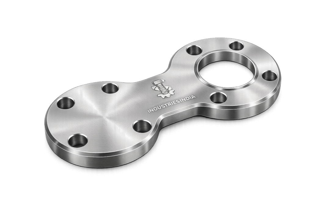
A Spectacle Blind Flange is a critical mechanical isolation device used in pressure piping systems to achieve positive, verifiable, and fail-safe isolation of process lines. Unlike valve-based isolation, which relies on sealing integrity over time, spectacle blinds provide physical separation of flow, ensuring zero passage when in the blind position.
In high-risk industrial environments, isolation is not only an operational requirement but also a safety mandate during:
- Plant shutdowns
- Maintenance activities
- Inspection cycles
- Hydrotesting
- Commissioning and decommissioning
The spectacle blind enables operators and inspection teams to visually confirm isolation status, eliminating ambiguity associated with closed valves.
Functional Importance in Process Safety
The adoption of spectacle blinds is directly tied to:
- Prevention of cross-contamination between process streams
- Elimination of residual flow leakage
- Assurance of personnel safety during line opening
- Compliance with lockout/tagout (LOTO) procedures
In contrast to temporary line blanking methods, spectacle blinds are permanently installed and engineered to withstand full system pressure conditions.
Primary Application Sectors
The use of Spectacle Blind Flange spans across high-integrity piping systems in:
Oil & Gas (Upstream / Midstream / Downstream)
- Pipeline isolation during pigging operations
- Wellhead maintenance isolation
- Refinery unit shutdowns
Refineries
- Distillation column isolation
- Heat exchanger line blocking
- Pump and compressor isolation
Petrochemical Plants
- Reactor feed line isolation
- Hazardous chemical containment
- Polymer processing units
Power Generation
- Steam line isolation
- Boiler feedwater systems
- Turbine auxiliary piping
LNG Terminals
- Cryogenic line isolation
- Storage tank maintenance
- Transfer line shutdown
Offshore Platforms
- Space-constrained isolation systems
- High-pressure subsea tie-ins
- Corrosion-critical environments
Why Spectacle Blinds Are Preferred
1. Over Valve Isolation
Valves are subject to:
- Seat wear
- Seal degradation
- Leakage under pressure
A Spectacle Blind Flange provides:
- Absolute shutoff
- No reliance on internal sealing components
- No risk of bypass leakage
2. Over Temporary Blinds
Temporary blinds require:
- Disassembly
- Additional manpower
- Risk during installation/removal
Spectacle blinds:
- Remain installed in-line
- Require only rotation for activation
- Reduce shutdown time
3. Over Spade & Spacer Combinations
Spade and spacer systems are separate components, requiring:
- Storage
- Handling logistics
- Risk of misplacement
Spectacle blinds integrate both into a single assembly, offering:
- Reduced handling complexity
- Permanent traceability
- Faster operational switching
2. Technical Definition
Definition
A Spectacle Blind Flange is a dual-disc mechanical isolation device consisting of:
- A solid blind plate (for complete flow blockage)
- A ring spacer (for unrestricted flow passage)
Both elements are permanently connected by a metal tie-bar (web), forming a structure resembling a pair of spectacles.
Core Components
1. Blind Plate (Solid Disc)
- Fully blocks flow
- Designed to withstand full system pressure
- Functions as a pressure-retaining boundary
2. Spacer Ring (Open Disc)
- Allows full flow continuity
- Matches internal pipe diameter
- Maintains system alignment during operation
3. Tie-Bar / Web Connection
- Connects blind and spacer
- Enables rotational switching
- Provides handling support for installation
Installation Configuration
A Spectacle Blind Flange is installed:
- Between two standard pipe flanges
- Typically Raised Face (RF) or Ring Type Joint (RTJ) configurations
- Using standard bolting and gasket systems
Operational Positions
Blind Position
- Solid plate aligned with pipe bore
- Flow is completely blocked
- Used during shutdown or maintenance
Spacer Position
- Ring aligned with pipe bore
- Flow is fully open
- Used during normal operation
Switching Mechanism
The spectacle blind is rotated manually after:
- Removal of flange bolts
- Separation of flanges
- Rotation of the spectacle assembly
- Reinstallation with new gasket (recommended)
This process ensures:
- Controlled isolation
- Mechanical verification
- Repeatable operation without component replacement
Super Industries
Global Manufacturer of Heavy & Custom Engineered Fasteners & Flanges
3. Engineering & Sealing Principle
Flange System Interaction
The Spectacle Blind Flange operates within a bolted flange joint system, where sealing integrity is achieved through:
- Bolt preload
- Gasket compression
- Contact surface finish
Blind Condition (Isolation Mode)
When the blind plate is engaged:
- The solid disc acts as a pressure barrier
- Internal pressure applies force on the blind face
- This force is resisted by:
- Flange bolts
- Gasket compression
- Plate thickness
Spacer Condition (Flow Mode)
When the spacer is engaged:
- The system behaves as a standard flanged joint
- Flow passes through the ring opening
- Gasket sealing prevents external leakage
Gasket Compression Behavior
Gasket performance depends on:
- Seating Stress (Initial Bolt Load)
- Operating Stress (Under Pressure & Temperature)
In both blind and spacer conditions:
- Proper gasket compression is critical
- Surface finish (Ra value) influences sealing efficiency
- Over-compression can damage gasket
- Under-compression leads to leakage
Contact Stress Distribution
- Uniform bolt tightening ensures even stress distribution
- Uneven stress leads to:
- Leakage paths
- Gasket failure
- Flange distortion
Bolt Preload Requirement
Bolt preload must satisfy:
- Gasket seating stress
- Internal pressure resistance
- External loads (thermal, vibration)
The preload is determined based on:
- Bolt material properties
- Flange rating
- Gasket type
Leakage Control Mechanism
Leak prevention is achieved through:
- Controlled bolt torque
- Proper gasket selection
- Surface finish compatibility
- Dimensional accuracy of spectacle blind
4. Pressure & Load Engineering
Applicable Pressure Classes
The Spectacle Blind Flange is manufactured in accordance with:
- ASME pressure classes:
- Class 150
- Class 300
- Class 600
- Class 900
- Class 1500
- Class 2500
Each class defines:
- Maximum allowable pressure
- Temperature limits
- Flange dimensions
Internal Pressure Load on Blind Plate
When in blind position:
- The blind plate experiences uniform pressure load
- Force is calculated as:

Where:
- ( P ) = Internal pressure
- ( A ) = Effective area of pipe bore
Bending Stress in Blind Plate
The blind behaves as a circular plate under pressure, leading to:
- Radial stress
- Circumferential stress
- Maximum stress at center
Design must ensure:
- Thickness sufficient to prevent yielding
- Compliance with ASME allowable stress limits
Bolt Load Redistribution
Under pressure:
- Internal force attempts to separate flanges
- Bolt load increases to counteract separation
- Load distribution depends on:
- Bolt spacing
- Number of bolts
- Flange rigidity
Thermal Expansion Effects
Temperature variations introduce:
- Differential expansion between:
- Flanges
- Bolts
- Spectacle blind
This can lead to:
- Loss of preload
- Excess stress
- Gasket relaxation
Material selection and bolt torque must account for:
- Operating temperature range
- Thermal cycling conditions
Safety Factors for Isolation
Design incorporates:
- Material safety factor
- Pressure containment margin
- Fatigue resistance for repeated use
Spectacle blinds used in critical systems are typically designed with:
- Conservative thickness
- Verified material properties
- Inspection traceability
Dimensional & Design Logic
Key Dimensions
A Spectacle Blind Flange is defined by:
- Outer Diameter (OD) – Matching flange OD
- Inner Diameter (ID) – For spacer ring
- Blind Thickness – Pressure-resisting element
- Spacer Thickness – Flow continuity element
- Tie-Bar Width & Thickness – Structural support
ASME B16.48 Dimensional Basis
The primary dimensional standard:
- Defines:
- Thickness values
- Diameter tolerances
- Pressure class compatibility
Ensures:
- Interchangeability across global projects
- Compatibility with ASME flanges
Alignment Considerations
Proper alignment is critical for:
- Preventing flange misfit
- Ensuring gasket seating
- Avoiding stress concentration
Tolerance factors include:
- Flatness
- Parallelism
- Concentricity
Thickness Design Logic
Blind Plate Thickness
- Based on pressure rating
- Higher class → thicker plate
Spacer Thickness
- Typically equal to gasket thickness + allowance
- Maintains flange spacing
Handling & Weight Considerations
Large-diameter spectacle blinds:
- Can exceed several hundred kilograms
- Require:
- Lifting lugs (if specified)
- Crane handling
- Proper rigging
Design must consider:
- Ease of rotation
- Safety during installation
- Space constraints in piping layout
Mechanical Integrity Factors
- Resistance to deformation under load
- Structural integrity of tie-bar
- Fatigue resistance for repeated switching
5. Applicable Standards (ASME / ASTM / DIN / ISO)
Primary Governing Standard: ASME B16.48
The Spectacle Blind Flange is fundamentally governed by ASME B16.48, which defines:
- Dimensional requirements for spectacle blinds, spades, and spacers
- Thickness values based on pressure class
- Acceptable tolerances for OD, ID, and web dimensions
- Pressure-temperature compatibility aligned with flange standards
This standard ensures:
- Interchangeability across EPC projects
- Compliance with global piping specifications
- Integration with ASME-compliant flange systems
Flange Compatibility Standards
Spectacle blinds are designed to match flange systems defined in:
ASME B16.5
- Covers pipe flanges up to NPS 24
- Defines:
- Bolt circle diameter
- Facing types (RF, RTJ)
- Pressure class ratings
ASME B16.47
- Covers large-diameter flanges (NPS 26 to NPS 60)
- Series A and Series B dimensional variations
Engineering Implication:
The Spectacle Blind Flange must align precisely with the mating flange standard to ensure:
- Bolt hole alignment
- Gasket seating compatibility
- Pressure boundary integrity
Material Standards (ASTM)
Material selection is governed by ASTM specifications to ensure:
- Mechanical strength
- Pressure retention capability
- Corrosion resistance
- Weldability and machinability
Applicable standards include:
- ASTM A105 – Forged carbon steel for ambient/high temperature
- ASTM A350 LF2 – Low-temperature carbon steel with impact properties
- ASTM A182 F304 / F316 – Austenitic stainless steels
- ASTM A182 F11 / F22 – Chromium-molybdenum alloy steels
- ASTM A182 F51 / F53 – Duplex and super duplex stainless steels
DIN / EN / ISO Equivalents
For international EPC projects, equivalent standards may apply:
- EN 1092-1 – Flanges and associated equipment
- DIN standards – Regional compliance in European installations
- ISO standards – Harmonization across global supply chains
Pressure-Temperature Mapping
Each material and pressure class combination must comply with:
- Allowable stress limits
- Temperature derating factors
- Service-specific conditions such as:
- Sour service (NACE compliance)
- Cryogenic applications
- High-temperature oxidation environments
6. Material & Grade Options
Material selection for a Spectacle Blind Flange is driven by:
- Operating pressure
- Temperature range
- Corrosive environment
- Mechanical loading conditions
Carbon Steel Grades
ASTM A105
- Standard forged carbon steel
- Suitable for:
- Ambient to moderate temperature service
- Hydrocarbon pipelines
- Advantages:
- High strength
- Cost efficiency
- Limitation:
- Limited corrosion resistance
ASTM A350 LF2
- Designed for low-temperature service
- Improved notch toughness
- Mandatory impact testing
Applications:
- LNG systems
- Cryogenic pipelines
Stainless Steel Grades
ASTM A182 F304
- General-purpose stainless steel
- Good corrosion resistance in:
- Atmospheric conditions
- Mild chemical environments
ASTM A182 F316
- Enhanced corrosion resistance due to molybdenum
- Suitable for:
- Chloride environments
- Marine conditions
- Chemical processing
Alloy Steel Grades
ASTM A182 F11 / F22
- Chromium-molybdenum steels
- Designed for:
- High-temperature service
- Power plant piping
Advantages:
- Creep resistance
- Thermal stability
Duplex & Super Duplex Stainless Steel
ASTM A182 F51 (Duplex)
- Balanced ferritic-austenitic structure
- High strength + corrosion resistance
ASTM A182 F53 (Super Duplex)
- Superior resistance to:
- Pitting
- Stress corrosion cracking
- Seawater exposure
Applications:
- Offshore platforms
- Subsea pipelines
- Marine environments
Material Comparison Table
| Grade | Yield Strength (MPa) | Tensile Strength (MPa) | Temperature Range (°C) | Corrosion Resistance | Typical Industry Use |
|---|---|---|---|---|---|
| ASTM A105 | ~250 | 485–620 | -29 to 425 | Low | Oil & Gas pipelines |
| ASTM A350 LF2 | ~250 | 485–620 | -46 to 345 | Low | LNG, cryogenic systems |
| ASTM A182 F304 | ~205 | 515–720 | -196 to 870 | Moderate | Process industries |
| ASTM A182 F316 | ~205 | 515–720 | -196 to 870 | High | Marine, chemical |
| ASTM A182 F11 | ~275 | 415–585 | Up to 540 | Moderate | Power plants |
| ASTM A182 F22 | ~415 | 585–760 | Up to 600 | Moderate | High-temp piping |
| ASTM A182 F51 | ~450 | 620–880 | -50 to 300 | High | Offshore |
| ASTM A182 F53 | ~550 | 750–950 | -50 to 300 | Very High | Seawater, subsea |
7. Heat Treatment Information
Heat treatment is applied to ensure:
- Mechanical strength
- Microstructural stability
- Resistance to brittle fracture
Normalizing
- Applied to carbon steel
- Refines grain structure
- Improves uniformity
Typical Result:
- Balanced strength and ductility
Quenching & Tempering (Q&T)
- Applied to alloy steels (F11, F22)
- Process:
- Rapid cooling (quenching)
- Controlled reheating (tempering)
Benefits:
- Increased strength
- Improved toughness
Solution Annealing
- Applied to stainless steels
- Dissolves carbides
- Restores corrosion resistance
Followed by:
- Rapid cooling to prevent sensitization
Stress Relieving
- Reduces residual stresses from machining
- Prevents distortion during service
Hardness & Impact Considerations
- Hardness controlled to avoid brittleness
- Charpy impact testing required for:
- Low-temperature service
- Critical applications
Typical Values:
- Carbon steel: 120–180 HB
- Alloy steel: 150–220 HB
- Stainless steel: Controlled via solution treatment
Manufacturing Process
The manufacturing of a Spectacle Blind Flange follows a controlled, traceable sequence to meet EPC and third-party inspection requirements.
1. Raw Material Inspection
- Verification of:
- Mill Test Certificates (MTC)
- Chemical composition
- Mechanical properties
- PMI (Positive Material Identification) conducted where required
2. Plate / Forging Selection
- Based on:
- Size
- Pressure class
- Material grade
Options:
- Forged blanks (preferred for high-pressure)
- Plate cut (used for larger diameters)
3. Profile Cutting
- CNC plasma / laser / waterjet cutting
- Ensures:
- Dimensional accuracy
- Minimal heat-affected zone
4. Machining Operations
- Outer diameter (OD) finishing
- Inner diameter (ID) machining (spacer side)
- Face finishing for gasket seating
Tolerance control critical for:
- Flange alignment
- Leak prevention
5. Drilling
- Handling holes or lifting provisions
- Not part of pressure boundary
6. Edge Finishing
- Removal of burrs
- Smooth edge preparation
Prevents:
- Handling injury
- Stress concentration
7. Heat Treatment
- As per material specification
- Controlled furnace cycles
- Recorded temperature logs
8. Surface Finishing
- Cleaning
- Coating or passivation
- Surface roughness control
9. Marking & Traceability
Each Spectacle Blind Flange is marked with:
- Material grade
- Heat number
- Pressure class
- Size
- Manufacturer identification
Ensures:
- Full traceability
- Compliance with inspection requirements
10. Surface Finish Options
Surface condition impacts:
- Corrosion resistance
- Gasket sealing performance
- Storage durability
Available Finishes
Anti-Rust Coating
- Temporary protection during transport
- Suitable for carbon steel
Black Painting
- Provides basic corrosion resistance
- Used in non-critical environments
Hot-Dip Galvanizing
- Zinc coating for corrosion protection
- Suitable for outdoor exposure
PTFE Coating
- Chemical resistance
- Reduces surface friction
Passivation (Stainless Steel)
- Removes free iron contamination
- Enhances corrosion resistance
Surface Roughness Considerations
- Gasket seating surfaces require controlled roughness (Ra)
- Typical values:
- RF: 3.2–6.3 µm
- RTJ: Precision machined grooves
Improper surface finish can lead to:
- Leakage
- Gasket damage
- Uneven stress distribution
A. Dimension Table (Indicative as per ASME B16.48)
The following table provides representative dimensions for a Spectacle Blind Flange aligned with ASME pressure classes. Final dimensions must always be verified against project specifications and applicable standards.
| Nominal Size (NPS) | OD (mm) | Blind Thickness (mm) | Spacer Thickness (mm) | Approx. Weight (kg) | Pressure Class |
|---|---|---|---|---|---|
| 2″ (DN50) | 152 | 19 | 6 | 3.5 | 150 |
| 4″ (DN100) | 229 | 25 | 6 | 8.5 | 150 |
| 6″ (DN150) | 279 | 32 | 6 | 15 | 150 |
| 8″ (DN200) | 343 | 38 | 8 | 28 | 300 |
| 10″ (DN250) | 406 | 44 | 8 | 45 | 300 |
| 12″ (DN300) | 483 | 51 | 10 | 70 | 300 |
| 16″ (DN400) | 597 | 64 | 12 | 130 | 600 |
| 20″ (DN500) | 711 | 76 | 12 | 220 | 600 |
| 24″ (DN600) | 813 | 89 | 14 | 350 | 900 |
Engineering Notes:
- Blind thickness increases with pressure class due to higher internal load
- Spacer thickness ensures flange spacing and gasket compression integrity
- Weight values are critical for lifting planning and installation safety
B. Pressure Rating Table (ASME Class vs Temperature)
Pressure ratings vary with temperature and material group. The table below provides a generalized reference for carbon steel (ASTM A105).
| ASME Class | Pressure @ 38°C (bar) | Pressure @ 200°C (bar) | Pressure @ 400°C (bar) |
|---|---|---|---|
| Class 150 | 19.6 | 15.6 | 10.3 |
| Class 300 | 51.1 | 40.8 | 27.2 |
| Class 600 | 102.1 | 81.7 | 54.5 |
| Class 900 | 153.2 | 122.5 | 81.7 |
| Class 1500 | 255.3 | 204.2 | 136.1 |
| Class 2500 | 425.5 | 340.4 | 227.0 |
Engineering Interpretation:
- Allowable pressure decreases with increasing temperature
- Material selection must consider derating factors
- Applicable to both flange and Spectacle Blind Flange as part of the pressure boundary
C. Handling Weight Table (Installation Planning)
Handling weight is a critical parameter for shutdown planning and rigging design.
| Nominal Size (NPS) | Approx. Weight (kg) | Handling Method Recommendation |
|---|---|---|
| Up to 4″ | <10 | Manual handling |
| 6″ – 10″ | 15–50 | Two-person lift / small hoist |
| 12″ – 16″ | 70–130 | Chain pulley block |
| 18″ – 24″ | 150–350 | Crane lifting required |
| Above 24″ | >350 | Engineered lifting plan |
Engineering Notes:
- Tie-bar strength must support handling loads
- Lifting lugs may be required for large sizes
- Rotation clearance must be considered during installation
D. Bolt Load Interaction Guide
The sealing integrity of a Spectacle Blind Flange depends on proper bolt load distribution.
1. Fundamental Load Relationship
Where:
- ( F ) = Force acting on blind plate
- ( P ) = Internal pressure
- ( A ) = Effective sealing area
2. Bolt Preload Requirement
Bolt preload must satisfy:

- ( F_{internal} ): Force due to internal pressure
- ( F_{gasket} ): Required gasket seating force
3. Gasket Seating Stress
- Initial bolt tightening creates seating stress
- Must exceed minimum gasket stress value
- Maintains seal before pressurization
4. Operating Condition
Under pressure:
- Internal force attempts flange separation
- Bolt load increases proportionally
- Gasket stress redistributes
5. Engineering Considerations
- Bolt material selection (yield strength)
- Torque control during tightening
- Lubrication impact on preload
- Number and diameter of bolts
Improper preload results in:
- Leakage
- Gasket failure
- Bolt fatigue
E. Mechanical Property Table
Mechanical properties vary by material and heat treatment condition.
| Material Grade | Yield Strength (MPa) | Tensile Strength (MPa) | Hardness (HB) | Impact Value (J @ -20°C) |
|---|---|---|---|---|
| ASTM A105 | 250 | 485–620 | 120–180 | Not mandatory |
| ASTM A350 LF2 | 250 | 485–620 | 120–180 | ≥27 J |
| ASTM A182 F304 | 205 | 515–720 | ≤201 | High |
| ASTM A182 F316 | 205 | 515–720 | ≤201 | High |
| ASTM A182 F11 | 275 | 415–585 | 130–200 | Moderate |
| ASTM A182 F22 | 415 | 585–760 | 150–220 | Moderate |
| ASTM A182 F51 | 450 | 620–880 | 250–310 | High |
| ASTM A182 F53 | 550 | 750–950 | 270–330 | High |
Engineering Notes:
- Impact values critical for low-temperature service
- Hardness limits ensure ductility and avoid brittle failure
- Duplex grades provide higher strength-to-weight ratio
F. Corrosion Resistance Table
Material selection must consider environmental exposure.
| Material | Marine Environment | Acidic Service | Hydrocarbon Service | High Humidity |
|---|---|---|---|---|
| Carbon Steel (A105) | Poor | Poor | Good | Moderate |
| SS304 | Moderate | Moderate | Good | Good |
| SS316 | Good | Good | Excellent | Excellent |
| Alloy Steel (F11/F22) | Moderate | Moderate | Excellent | Moderate |
| Duplex (F51) | Excellent | Good | Excellent | Excellent |
| Super Duplex (F53) | Outstanding | Excellent | Excellent | Outstanding |
Engineering Interpretation:
- Carbon steel requires coating in corrosive environments
- SS316 preferred for chloride exposure
- Duplex grades used in offshore and seawater applications
8. Inspection & Quality Control Methods
Inspection ensures that each Spectacle Blind Flange meets design, material, and dimensional requirements before dispatch.
1. Positive Material Identification (PMI)
- Verifies alloy composition
- Ensures correct grade usage
- Required for:
- Stainless steel
- Alloy steel
- Critical service applications
2. Ultrasonic Testing (UT)
- Detects internal defects
- Applicable for:
- Forged components
- Thick sections
Ensures:
- Absence of internal discontinuities
3. Magnetic Particle Inspection (MPI)
- Surface and near-surface crack detection
- Applicable to ferromagnetic materials
4. Dye Penetrant Inspection (DPI)
- Surface crack detection for non-magnetic materials
- Used for stainless steel and non-ferrous alloys
5. Dimensional Inspection
Verification of:
- OD, ID, thickness
- Flatness and parallelism
- Web alignment
Ensures compatibility with flange systems
6. Hardness Testing
- Confirms heat treatment effectiveness
- Ensures compliance with material standards
7. Third-Party Inspection (TPI)
Conducted by:
- Independent inspection agencies
- As per project requirements
Scope includes:
- Stage inspection
- Final inspection
- Documentation verification
8. Certification (EN 10204)
Certification
- Manufacturer-issued test certificate
- Confirms compliance with order
Certification
- Third-party validated certificate
- Required for critical EPC projects
Inspection Documentation Includes:
- Mill Test Certificates (MTC)
- Heat treatment charts
- NDT reports (UT, MPI, DPI)
- Dimensional inspection reports
- PMI reports
- Compliance certificates
9. Industries Served
The Spectacle Blind Flange is deployed across industries where positive mechanical isolation, pressure boundary integrity, and shutdown safety are mandatory.
Oil & Gas Industry
Upstream (Exploration & Production)
- Wellhead isolation during intervention
- Flowline shutdown for maintenance
- Separation systems requiring physical isolation
Midstream (Transmission Pipelines)
- Pipeline sectional isolation
- Pig launcher and receiver systems
- Compressor station maintenance
Downstream (Refining & Processing)
- Process unit isolation (distillation, cracking)
- Heat exchanger and reactor maintenance
- Pump and compressor isolation
Engineering Requirement:
High-pressure classes (600–2500), corrosion-resistant materials, and strict compliance with ASME standards.
Refineries
- Crude distillation units
- Hydrocracking and reforming units
- Sulfur recovery systems
Spectacle blinds are used to:
- Ensure zero leakage during shutdown
- Provide visual confirmation of isolation
- Maintain compliance with safety protocols
Petrochemical Plants
- Polymer processing units
- Chemical reactors
- Hazardous fluid handling systems
Material Consideration:
Stainless steel (F316) and duplex grades for chemical resistance.
Power Generation
Thermal Power Plants
- Steam line isolation
- Boiler feedwater systems
Combined Cycle Plants
- Gas turbine auxiliary piping
- Heat recovery steam generator (HRSG) systems
Engineering Requirement:
Alloy steels (F11/F22) for high-temperature service and creep resistance.
LNG & Cryogenic Systems
- Storage tank isolation
- Transfer line shutdown
- Cryogenic valve maintenance
Material Requirement:
ASTM A350 LF2 and stainless steel for low-temperature toughness.
Offshore & Marine Installations
- Subsea tie-ins
- Platform piping systems
- Seawater handling systems
Material Requirement:
Duplex and super duplex stainless steels for corrosion resistance and high strength.
10. Export Capability & Global Supply
Super Industries supplies Spectacle Blind Flange components for international EPC projects with documentation and logistics aligned to global standards.
Export Regions
- United States (ASME-compliant projects)
- European Union (EN/DIN compliance)
- Middle East (oil & gas infrastructure)
- Southeast Asia (petrochemical and power sectors)
Packaging Standards
- Wooden crates (ISPM-15 compliant)
- Moisture-resistant wrapping
- Anti-corrosion protection (VCI / coating)
- Marking protection for traceability
Documentation Package
Each shipment includes:
- Mill Test Certificates (MTC)
- EN 10204 3.1 / 3.2 certification
- Inspection reports (NDT, dimensional)
- Heat treatment records
- Packing list and traceability documentation
Logistics Capability
- Bulk project shipment handling
- Containerized export
- Coordination with EPC procurement schedules
- Handling of oversized and heavy components
11. PROCUREMENT & INSTALLATION VIEW
Procurement Considerations
For EPC and project procurement teams, the following parameters define specification clarity:
- Nominal size (NPS / DN)
- Pressure class (ASME rating)
- Material grade (ASTM specification)
- Facing type (RF / RTJ)
- Applicable standards (ASME B16.48, B16.5, B16.47)
- Inspection requirements (TPI, certification level)
- Surface finish and coating requirements
Installation Procedure
Installation of a Spectacle Blind Flange must follow controlled procedures to maintain sealing integrity and safety.
1. Pre-Installation Checks
- Verify material grade and markings
- Inspect gasket surfaces for damage
- Confirm dimensional compatibility with flanges
- Ensure cleanliness of mating surfaces
2. Positioning Between Flanges
- Insert spectacle blind between flange faces
- Ensure correct alignment of:
- Bolt holes
- Gasket seating surfaces
3. Gasket Placement
- Select gasket based on:
- Pressure class
- Temperature
- service medium
- Place centrally to avoid misalignment
4. Bolt Installation & Tightening
- Insert bolts and nuts
- Apply lubrication where required
- Tighten using cross-pattern sequence
5. Torque Application
- Apply torque in stages:
- 30% → 60% → 100% of required torque
- Ensures uniform gasket compression
6. Final Inspection
- Check bolt tightness
- Verify alignment
- Confirm correct installation position (blind/spacer)
12. Switching Between Blind and Spacer
Procedure
- Depressurize and isolate the line
- Remove flange bolts
- Separate flange faces
- Rotate the spectacle blind
- Replace gasket (recommended)
- Reinstall and tighten bolts
Safety Considerations
- Ensure complete depressurization
- Use lifting equipment for large sizes
- Avoid manual handling for heavy components
- Confirm alignment before tightening
Bolt Tightening Sequence (Engineering Guidance)
- Use star/cross tightening pattern
- Prevents uneven stress distribution
- Minimizes risk of leakage
Gasket Replacement Requirement
- Recommended during every switching operation
- Prevents:
- Seal degradation
- Leakage due to compressed gasket reuse
13. CUSTOM ENGINEERING CAPABILITIES
Super Industries manufactures Spectacle Blind Flange solutions for project-specific requirements.
Large Diameter Capability
- Manufacturing up to large NPS sizes (as per ASME B16.47)
- Plate-based or forged construction
High-Pressure Custom Thickness
- Designed for:
- Class 1500 / 2500 applications
- Increased blind thickness for pressure resistance
Special Material Supply
- Duplex / Super Duplex
- Nickel alloys (on project requirement)
- Low-temperature carbon steel
NACE Compliance
- Suitable for sour service environments
- Controlled hardness levels
- Sulfide stress cracking resistance
Project-Specific Marking
- Tagging as per client specification
- Heat number traceability
- Barcode / identification systems (if required)
FINAL ENGINEERING CONCLUSION
The Spectacle Blind Flange functions as a mechanically reliable, pressure-rated isolation device within piping systems where absolute shutoff and visual verification are mandatory.
From an EPC and engineering standpoint, its selection and application are governed by:
- ASME B16.48 dimensional and pressure standards
- Compatibility with ASME B16.5 / B16.47 flange systems
- Material selection based on pressure, temperature, and corrosion conditions
- Proper bolt load application and gasket sealing behavior
- Controlled installation and switching procedures
System-Level Engineering Value
- Provides positive isolation independent of valve integrity
- Ensures zero leakage condition during maintenance
- Enables safe shutdown operations
- Supports inspection and compliance requirements
Procurement-Level Evaluation Outcome
For EPC contractors and technical evaluators, a compliant Spectacle Blind Flange manufacturer must demonstrate:
- Standards alignment (ASME / ASTM)
- Material traceability and certification
- Manufacturing process control
- Inspection and testing capability
- Export documentation readiness
Application Integrity Summary
When correctly specified, manufactured, inspected, and installed, the Spectacle Blind Flange delivers:
- Reliable pressure containment
- Repeatable isolation performance
- Long-term operational integrity
- Compliance with global piping standards