
ASME B16.5 Flat Flanges
Super Industries
“Global Manufacturer of Heavy & Custom Engineered Fasteners for Oil & Gas, Power & EPC Contractors.”
1. Industry Context & System Relevance
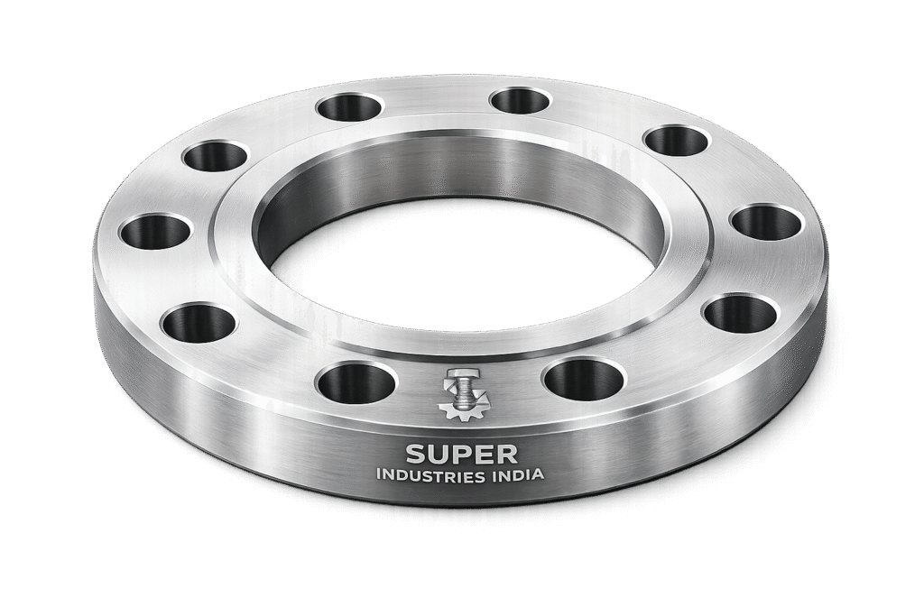
Role of ASME B16.5 Flat Flanges in Engineered Systems
ASME B16.5 Flat Flanges function as pressure-retaining, bolted mechanical connectors within piping systems, enabling controlled assembly and disassembly of pipelines, equipment nozzles, valves, and pressure vessels.
They are used extensively in:
- Process piping networks
- Pressure vessel nozzle connections
- Pump and compressor interfaces
- Heat exchanger connections
- Storage tank piping systems
Flat Face (FF) flanges are specifically applied where mating components require uniform contact without localized stress concentration.
System-Level Importance
In engineered piping systems, flanged joints provide:
- Detachable connections for maintenance and inspection
- Alignment flexibility during installation
- Isolation capability for operational safety
- Ease of gasket replacement without cutting or welding
Compared to welded joints:
| Parameter | Flanged Joint | Welded Joint |
|---|---|---|
| Maintenance | High accessibility | Limited |
| Installation | Faster | Slower |
| Inspection | Easy | Complex |
| Disassembly | Possible | Not possible |
Industry Applications
Oil & Gas
- Wellhead surface piping
- Low-pressure utility lines
- Firewater systems
Refineries
- Cooling water networks
- Utility piping systems
Petrochemical Plants
- Chemical transfer lines
- Storage tank connections
Power Generation
- Boiler auxiliary piping
- Cooling water circuits
LNG Terminals
- Low-pressure service lines
- Cryogenic auxiliary systems
Water Treatment Plants
- Pump discharge lines
- Clarifier systems
Chemical Processing
- Corrosive media handling (with suitable materials)
Why Flanged Joints Are Preferred
Flanged systems are selected where:
- Periodic maintenance is required
- Equipment replacement is expected
- Gasket sealing is critical
- Inspection access is necessary
Flat face flanges specifically reduce risk of:
- Flange cracking in brittle materials
- Uneven gasket compression
2. Technical Definition
Definition of ASME B16.5 Flat Flanges
ASME B16.5 Flat Flanges (Flat Face – FF) are:
- Pressure-retaining bolted connections
- Manufactured as per ASME B16.5 dimensional standard
- Designed with a completely flat gasket seating surface
- Used with full-face gaskets covering entire flange face
Key Characteristics
- No raised sealing surface
- Uniform gasket contact area
- Suitable for lower pressure classes
- Compatible with cast iron and ductile iron equipment
Flange Facing Types Comparison
| Facing Type | Description | Application |
|---|---|---|
| Flat Face (FF) | Entire face is flat | Low-pressure, brittle materials |
| Raised Face (RF) | Raised sealing area | General industrial service |
| Ring Type Joint (RTJ) | Grooved face for metal gasket | High pressure & temperature |
Pressure Classes (ASME B16.5)
Flat face flanges are available in:
- Class 150
- Class 300
- Class 600
- Class 900
- Class 1500
- Class 2500
However, FF configuration is primarily used in:
- Class 150
- Class 300
Types of Flat Face Flanges
Under ASME B16.5:
- Slip-On Flat Face Flange
- Blind Flat Face Flange
- Socket Weld Flat Face Flange
- Threaded Flat Face Flange
Super Industries
Global Manufacturer of Heavy & Custom Engineered Fasteners & Flanges
3. Engineering & Sealing Principle
Bolt Preload Mechanics
The sealing performance of ASME B16.5 Flat Flanges depends on:
- Bolt tightening force
- Gasket compression
- Uniform load distribution
When bolts are tightened:
- Tensile force is generated in bolts
- Compressive force is applied to gasket
- Flange faces transfer load evenly across full surface
Full-Face Gasket Behavior
Flat face flanges use full-face gaskets, which:
- Cover entire flange surface
- Include bolt holes
- Distribute load across full diameter
Advantages:
- Reduced localized stress
- Improved sealing for low-pressure systems
- Protection of flange face
Load Distribution
Unlike RF flanges:
- Load is distributed over entire flange face
- No stress concentration at raised portion
- Reduced risk of flange distortion
Flange Face Finish (Surface Roughness)
Typical surface roughness:
- Ra: 3.2 – 6.3 µm
This ensures:
- Adequate gasket grip
- Controlled leakage paths
- Uniform compression
Gasket Seating Stress
Sealing requires:
- Minimum gasket seating stress
- Controlled compression without overloading
Factors influencing:
- Gasket material
- Bolt preload
- Flange stiffness
Leakage Prevention Mechanism
Leakage is prevented by:
- Creating a seal through gasket deformation
- Filling micro-irregularities on flange surface
- Maintaining compression under operating conditions
4. Pressure & Load Engineering
Pressure-Temperature Ratings
ASME B16.5 defines:
- Allowable pressure based on temperature
- Material-dependent limits
Example:
- Carbon steel Class 150 at ambient temperature supports higher pressure than at elevated temperatures
Internal Pressure vs Bolt Load
Relationship:
- Internal pressure creates separating force
- Bolt preload must exceed this force
Hydrostatic force:

Where:
- ( P ) = Internal pressure
- ( A ) = Effective area
External Loads
Flanges are also subjected to:
- Piping weight
- Thermal expansion
- Vibration
- Misalignment forces
Design Considerations
- Bolt stress limits
- Flange rigidity
- Gasket compression limits
- Safety factors
Failure Modes
| Failure Type | Cause |
|---|---|
| Leakage | Insufficient preload |
| Bolt failure | Overloading |
| Flange distortion | Uneven tightening |
| Gasket blowout | Excess pressure |
Dimensional & Design Logic
Critical Dimensions
- Outside Diameter (OD)
- Bolt Circle Diameter (BCD)
- Number of Bolt Holes
- Bolt Hole Diameter
- Flange Thickness
- Facing Type (Flat Face)
Design Logic
Each dimension is defined to ensure:
- Proper bolt load transfer
- Uniform gasket compression
- Structural integrity
ASME Dimensional Tolerances
- Controlled machining tolerances
- Standardized bolt hole alignment
- Face flatness requirements
Geometric Requirements
- Concentricity between bore and OD
- Perpendicularity of face to bore
- Flatness of sealing surface
Surface Finish Requirements
Flat face flanges must maintain:
- Uniform surface finish
- Absence of tool marks
- No radial scoring
5. Applicable Standards
Primary Governing Standard — ASME B16.5
ASME B16.5 Flat Flanges are manufactured in accordance with:
- ASME B16.5 — Pipe Flanges and Flanged Fittings
This standard defines:
- Pressure-temperature ratings
- Dimensions (OD, BCD, thickness, bolt holes)
- Facing types (including Flat Face)
- Tolerances
- Marking requirements
Scope Coverage
ASME B16.5 applies to:
- NPS ½” to 24”
- Pressure Classes: 150 to 2500
- Materials including carbon steel, alloy steel, and stainless steel
Material Standards (ASTM)
Flange material selection is governed by ASTM specifications:
Carbon Steel
- ASTM A105 — Forged carbon steel for ambient and high-temperature service
- ASTM A350 LF2 — Low-temperature carbon steel
Stainless Steel
- ASTM A182 F304 / F304L
- ASTM A182 F316 / F316L
Alloy Steel
- ASTM A182 F11
- ASTM A182 F22
These standards define:
- Chemical composition
- Mechanical properties
- Heat treatment requirements
International Equivalents (Reference Comparison)
| ASME / ASTM | EN / DIN Equivalent | Application Context |
|---|---|---|
| ASTM A105 | EN 1.0460 (C22.8) | General piping |
| ASTM A182 F304 | EN 1.4301 | Corrosion-resistant systems |
| ASTM A182 F316 | EN 1.4401 | Marine / chemical |
MSS Standards (Supplementary)
Where applicable:
- MSS SP-44 (large diameter flanges beyond ASME B16.5 scope)
- MSS SP-6 (surface finish practices)
Standards Mapping to Service Conditions
| Condition | Standard Reference |
|---|---|
| High temperature | ASTM A105 / A182 |
| Low temperature | ASTM A350 LF2 |
| Corrosive service | ASTM A182 F316 |
| General service | ASME B16.5 |
6. Material & Grade Options
Material Selection Philosophy
Material selection for ASME B16.5 Flat Flanges is based on:
- Operating temperature
- Internal pressure
- Corrosion environment
- Fluid characteristics
- Project specifications
Carbon Steel Grades
ASTM A105
- Standard forged carbon steel
- Suitable for ambient to moderately high temperatures
- Used in oil & gas and general piping
ASTM A350 LF2
- Designed for low-temperature service
- Impact-tested
- Used in cryogenic or sub-zero environments
Stainless Steel Grades
ASTM A182 F304
- General corrosion resistance
- Suitable for water and mild chemicals
ASTM A182 F316
- Enhanced corrosion resistance
- Resistant to chlorides and marine environments
Alloy Steel Grades
ASTM A182 F11 / F22
- Chromium-molybdenum alloy steels
- High-temperature strength
- Used in power plants and high-pressure systems
Material Comparison Table
| Grade | Yield Strength (MPa) | Tensile Strength (MPa) | Temperature Range | Corrosion Resistance | Typical Application |
|---|---|---|---|---|---|
| ASTM A105 | ≥ 250 | 485–620 | -29°C to 425°C | Low | Oil & gas piping |
| ASTM A350 LF2 | ≥ 250 | 485–620 | -46°C to 345°C | Low | Low-temp service |
| ASTM A182 F304 | ≥ 205 | 515–720 | -196°C to 870°C | Moderate | Water, chemicals |
| ASTM A182 F316 | ≥ 205 | 515–720 | -196°C to 870°C | High | Marine, chemical |
| ASTM A182 F11 | ≥ 275 | 415–585 | Up to 540°C | Moderate | Power plants |
| ASTM A182 F22 | ≥ 415 | 585–760 | Up to 600°C | Moderate | High-temp systems |
7. Heat Treatment
Purpose of Heat Treatment
Heat treatment ensures:
- Mechanical strength
- Structural integrity
- Stress relief
- Compliance with ASTM requirements
Common Heat Treatment Processes
1. Normalizing
- Heating above critical temperature
- Air cooling
Effect:
- Refined grain structure
- Improved toughness
2. Quenching & Tempering (Q&T)
- Rapid cooling (quenching)
- Followed by controlled reheating (tempering)
Effect:
- High strength
- Improved ductility
- Reduced brittleness
3. Stress Relieving
- Heating below transformation temperature
- Controlled cooling
Effect:
- Reduction of residual stresses
- Dimensional stability
4. Solution Annealing (Stainless Steel)
- Heating to high temperature
- Rapid cooling
Effect:
- Dissolution of carbides
- Improved corrosion resistance
Hardness Control
Typical hardness ranges:
| Material | Hardness (HB) |
|---|---|
| A105 | 137 – 187 |
| LF2 | 121 – 187 |
| F304 | ≤ 201 |
| F316 | ≤ 217 |
Impact Testing
For low-temperature applications:
- Charpy V-notch testing is performed
- Ensures toughness at sub-zero conditions
Microstructure Control
Heat treatment controls:
- Grain size
- Phase distribution
- Inclusion structure
This directly affects:
- Fatigue resistance
- Crack propagation behavior
8. Manufacturing Process
1. Raw Material Inspection
- Verification of mill test certificates
- Chemical composition analysis
- Visual inspection
2. Forging / Plate Cutting
Depending on flange type:
- Closed-die forging (preferred for strength)
- Plate cutting (for specific applications)
3. Heat Treatment (Initial Stage)
- Applied after forging
- Ensures uniform properties
4. CNC Machining
Precision machining includes:
- Outer diameter
- Bore
- Flange thickness
- Facing surface
5. Drilling of Bolt Holes
- CNC-controlled drilling
- Ensures accurate BCD
- Maintains hole alignment
6. Facing Machining
Flat face finishing:
- Controlled surface roughness
- Uniform sealing surface
7. Secondary Heat Treatment (if required)
- Stress relieving
- Final mechanical property adjustment
8. Surface Coating
Depending on requirement:
- Anti-rust oil
- Black coating
- Galvanizing
- Passivation
9. Final Inspection
- Dimensional verification
- NDT testing
- Surface quality check
10. Marking & Traceability
Marking includes:
- Manufacturer identification (Super Industries)
- Material grade
- Pressure class
- Heat number
- Size
Ensures full traceability from raw material to finished product
Surface Finish Options
Protective Coatings
| Coating Type | Application |
|---|---|
| Anti-rust oil | Temporary protection |
| Black coating | Indoor storage |
| Zinc plating | Corrosion resistance |
| Hot-dip galvanizing | Outdoor / water exposure |
| Passivation | Stainless steel |
Flange Face Roughness
Flat face surface finish:
- Ra: 3.2 – 6.3 µm
This range ensures:
- Adequate gasket grip
- Controlled sealing
- Minimal leakage paths
Surface Integrity Requirements
- No scratches
- No dents
- No corrosion pits
- No machining defects
A. Dimensional Tables (ASME B16.5 Flat Flanges)
The following table represents standard dimensional parameters for ASME B16.5 Flat Flanges (Class 150). Values are indicative and aligned with ASME B16.5 dimensional framework.
Units: mm (unless specified)
| NPS | OD (D) | BCD (K) | Bolt Size | No. of Holes | Flange Thickness (T) |
|---|---|---|---|---|---|
| ½” | 89 | 60.3 | M12 | 4 | 9.6 |
| ¾” | 99 | 69.9 | M12 | 4 | 11.2 |
| 1” | 108 | 79.4 | M12 | 4 | 12.7 |
| 1½” | 127 | 98.4 | M16 | 4 | 14.3 |
| 2” | 152 | 120.7 | M16 | 4 | 15.9 |
| 3” | 191 | 152.4 | M16 | 4 | 19.1 |
| 4” | 229 | 190.5 | M16 | 8 | 23.9 |
| 6” | 279 | 241.3 | M20 | 8 | 25.4 |
| 8” | 343 | 298.5 | M20 | 8 | 28.6 |
| 10” | 406 | 362 | M24 | 12 | 30.2 |
| 12” | 483 | 431.8 | M24 | 12 | 31.8 |
Dimensional Engineering Notes
- Bolt Circle Diameter (BCD) ensures uniform load distribution
- Thickness (T) increases with size to resist bending stress
- Number of bolts increases to maintain sealing integrity
- Tolerance limits must comply with ASME B16.5 machining requirements
B. Pressure–Temperature Rating Table (Indicative)
For ASTM A105 (Carbon Steel) Flat Face Flanges:
| Temperature (°C) | Class 150 Pressure (bar) | Class 300 Pressure (bar) |
|---|---|---|
| 38 | 19.6 | 51.1 |
| 100 | 17.7 | 46.2 |
| 200 | 15.2 | 39.5 |
| 300 | 13.3 | 34.5 |
| 400 | 10.2 | 26.5 |
Engineering Interpretation
- Pressure rating decreases with temperature
- Material strength reduction governs allowable pressure
- Design must consider maximum operating temperature
C. Torque Chart
Bolt Torque Values for ASME B16.5 Flat Flanges
Values are indicative for common bolting materials:
Lubricated vs Dry Torque (Nm)
| Bolt Size | ASTM A193 B7 (Lubricated) | ASTM A193 B7 (Dry) | Class 8.8 | Class 10.9 |
|---|---|---|---|---|
| M12 | 70 | 95 | 80 | 110 |
| M16 | 170 | 230 | 190 | 260 |
| M20 | 340 | 460 | 380 | 520 |
| M24 | 580 | 780 | 650 | 900 |
| M27 | 850 | 1150 | 950 | 1300 |
| M30 | 1150 | 1550 | 1300 | 1750 |
Torque Application Notes
- Lubrication reduces friction → lower torque required
- Dry bolts require higher torque due to friction
- Torque must be applied in controlled increments
- Final torque achieved in minimum 3–4 passes
D. Preload Calculation Guide
1. Bolt Stress Formula

Where:
- ( \sigma_b ) = Bolt stress
- ( F_b ) = Bolt force
- ( A_b ) = Tensile stress area
2. Preload Force Requirement

3. Hydrostatic Force
Where:
- ( P ) = Internal pressure
- ( A ) = Internal pipe area
4. Gasket Seating Force

Where:
- ( m ) = Gasket factor
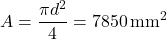
5. Sample Calculation
Given:
- Pressure = 35 bar
- Pipe diameter = 100 mm
Area:
Hydrostatic Force:

Total preload must exceed:
- Hydrostatic force
- Gasket seating force
Engineering Interpretation
- Bolt preload must always exceed separating forces
- Safety factor typically applied (1.5 – 2.5)
- Uneven preload leads to leakage
E. Mechanical Properties Table
| Material | Yield Strength (MPa) | Tensile Strength (MPa) | Elongation (%) | Hardness (HB) |
|---|---|---|---|---|
| ASTM A105 | ≥ 250 | 485–620 | ≥ 22 | 137–187 |
| ASTM A350 LF2 | ≥ 250 | 485–620 | ≥ 22 | 121–187 |
| ASTM A182 F304 | ≥ 205 | 515–720 | ≥ 30 | ≤ 201 |
| ASTM A182 F316 | ≥ 205 | 515–720 | ≥ 30 | ≤ 217 |
| ASTM A182 F11 | ≥ 275 | 415–585 | ≥ 20 | ≤ 187 |
| ASTM A182 F22 | ≥ 415 | 585–760 | ≥ 18 | ≤ 217 |
F. Corrosion Resistance Table
| Material | Marine | Chemical | Humidity | Hydrocarbon |
|---|---|---|---|---|
| Carbon Steel (A105) | Poor | Poor | Moderate | Good |
| Stainless Steel 304 | Moderate | Moderate | Good | Good |
| Stainless Steel 316 | Excellent | Excellent | Excellent | Good |
| Alloy Steel (F11/F22) | Moderate | Moderate | Moderate | Excellent |
9. Inspection & Quality Control
Inspection Philosophy
Inspection ensures:
- Compliance with ASME B16.5
- Material traceability
- Structural integrity
- Dimensional accuracy
1. Positive Material Identification (PMI)
- Confirms chemical composition
- Ensures correct material grade
- Conducted using spectrometers
2. Ultrasonic Testing (UT)
- Detects internal defects
- Identifies inclusions and voids
- Applicable for forged flanges
3. Magnetic Particle Inspection (MPI)
- Detects surface and near-surface cracks
- Applicable for ferromagnetic materials
4. Dye Penetrant Inspection (DPI)
- Used for stainless steel and non-magnetic materials
- Detects surface discontinuities
5. Dimensional Inspection
Verification of:
- OD, BCD, thickness
- Bolt hole alignment
- Flatness of face
6. Hardness Testing
- Ensures compliance with material specifications
- Confirms heat treatment effectiveness
7. Hydrostatic Testing (If Applicable)
- Conducted in assembled systems
- Verifies sealing performance
8. Surface Inspection
- Visual examination
- Detection of machining defects
- Corrosion or surface irregularities
9. Certification & Documentation
EN 10204 Certification
- 3.1 Certificate — Manufacturer test report
- 3.2 Certificate — Third-party validated
10. Third-Party Inspection (TPI)
Inspection agencies may include:
- Client-appointed inspectors
- Independent certification bodies
Scope includes:
- Raw material verification
- In-process inspection
- Final inspection and documentation
10. Industries Served
ASME B16.5 Flat Flanges are deployed across multiple process industries where controlled sealing, accessibility, and compatibility with low to moderate pressure systems are required.
Oil & Gas
Applications include:
- Utility piping systems
- Firewater distribution networks
- Storage tank connections
- Low-pressure hydrocarbon service
Engineering Requirement:
- Reliability under cyclic operation
- Compatibility with carbon steel piping
- Ease of inspection and replacement
Petrochemical Plants
Used in:
- Chemical transfer lines
- Cooling water circuits
- Auxiliary process systems
Material Preference:
- Stainless steel (F304 / F316) for corrosion resistance
- Carbon steel for non-corrosive service
Power Generation
Applications:
- Cooling water systems
- Boiler auxiliary lines
- Condensate piping
Engineering Focus:
- Thermal expansion management
- Structural stability under vibration
LNG Terminals
Used in:
- Low-pressure auxiliary lines
- Utility systems
Material Requirement:
- ASTM A350 LF2 for low-temperature service
Water Treatment Plants
Applications:
- Pump discharge piping
- Clarifier systems
- Filtration networks
Advantages of Flat Face Flanges:
- Uniform gasket compression
- Compatibility with cast iron pumps and valves
Chemical Processing Industries
Used where:
- Corrosive fluids are handled
- Frequent maintenance is required
Material Selection:
- Stainless steel (F316) for aggressive environments
11. Procurement & Installation View
Procurement Considerations
EPC and procurement teams evaluate ASME B16.5 Flat Flanges based on:
- Compliance with ASME B16.5
- Material certification (ASTM)
- Pressure class suitability
- Dimensional accuracy
- Inspection documentation
Documentation Requirements
Typical supply documentation includes:
- Mill Test Certificates (MTC)
- Heat treatment records
- NDT reports (UT, MPI, DPI)
- Dimensional inspection reports
- EN 10204 3.1 / 3.2 certification
Gasket Selection
Flat face flanges require:
- Full-face gaskets
- Materials such as:
- Non-asbestos fiber
- PTFE
- Rubber (EPDM, NBR)
Selection Criteria:
- Pressure
- Temperature
- Fluid compatibility
Bolt Tightening Sequence
Proper tightening is critical to sealing integrity.
Cross (Star) Pattern Tightening
- Initial snug tightening
- 30% torque application
- 60% torque application
- 100% final torque
Ensures:
- Uniform gasket compression
- Avoidance of flange distortion
Torque Application Practice
- Use calibrated torque wrench
- Apply torque in multiple passes
- Verify torque after 24 hours (re-torque if required)
Field Inspection Checkpoints
- Surface cleanliness
- Gasket alignment
- Bolt lubrication condition
- Torque verification
- Flange face condition
Storage & Handling
To maintain integrity:
- Store in dry, covered environment
- Protect flange faces with covers
- Avoid stacking damage
- Apply protective coating if required
12. Export Capability
Global Supply Regions
Super Industries supplies ASME B16.5 Flat Flanges to:
- United States
- European Union
- Middle East (UAE, Saudi Arabia, Qatar)
- Southeast Asia
Export Packaging Standards
- Wooden crates (fumigated)
- Palletized loads
- Moisture protection wrapping
- Face protection covers
Logistics Handling
- Containerized shipping (FCL / LCL)
- Break bulk for large consignments
- Marking for identification and traceability
Export Documentation
Provided documentation includes:
- Commercial invoice
- Packing list
- Certificate of origin
- Mill test certificates
- Inspection release notes
Compliance & Traceability
Each flange is traceable through:
- Heat number
- Material grade
- Manufacturing batch
Ensures alignment with:
- EPC documentation requirements
- Third-party inspection protocols
13. Custom Engineering Capabilities
Super Industries supports project-specific requirements beyond standard ASME configurations.
Custom Drilling
- Non-standard bolt hole patterns
- Special bolt sizes
- Project-specific BCD modifications
Custom Thickness
- Increased flange thickness for higher rigidity
- Reinforcement for special loading conditions
Special Coatings
- PTFE coating
- Epoxy coating
- High-temperature coatings
Project-Specific Marking
- Client tagging systems
- Barcode / QR traceability
- Heat-wise identification
Dimensional Modifications
- Bore customization
- Facing adjustments
- Compatibility with legacy systems
Engineering Compliance Summary
ASME B16.5 Flat Flanges manufactured by Super Industries conform to:
- ASME B16.5 dimensional and pressure standards
- ASTM material specifications
- Controlled heat treatment processes
- Verified inspection and testing procedures
Engineering Integrity Factors
- Uniform gasket sealing via flat face geometry
- Controlled bolt preload and torque application
- Verified material properties and traceability
- Dimensional precision aligned with EPC requirements
Performance Reliability
These flanges are engineered to:
- Maintain sealing under pressure and temperature variations
- Resist deformation under bolt load
- Enable repeatable assembly and disassembly
- Support inspection and maintenance cycles
Conclusion
ASME B16.5 Flat Flanges are a defined solution for:
- Low to moderate pressure piping systems
- Applications requiring uniform gasket compression
- Installations involving brittle equipment materials
- Systems requiring frequent maintenance access
Their engineering relevance lies in:
- Controlled sealing behavior
- Standardized dimensional compatibility
- Material adaptability across service conditions
From a procurement and engineering evaluation perspective, these flanges meet:
- Pressure-temperature rating requirements
- Dimensional compliance criteria
- Inspection and certification expectations
- Installation and operational reliability standards
Final Engineering Position
For EPC contractors, consultants, and inspection authorities:
ASME B16.5 Flat Flanges represent a standardized, mechanically reliable, and inspection-accessible connection method within pressure piping systems when applied within defined service limits and material constraints.