
API FLANGES
Super Industries
“Global Manufacturer of Heavy & Custom Engineered Fasteners for Oil & Gas, Power & EPC Contractors.”
1. Industry Context & System Relevance
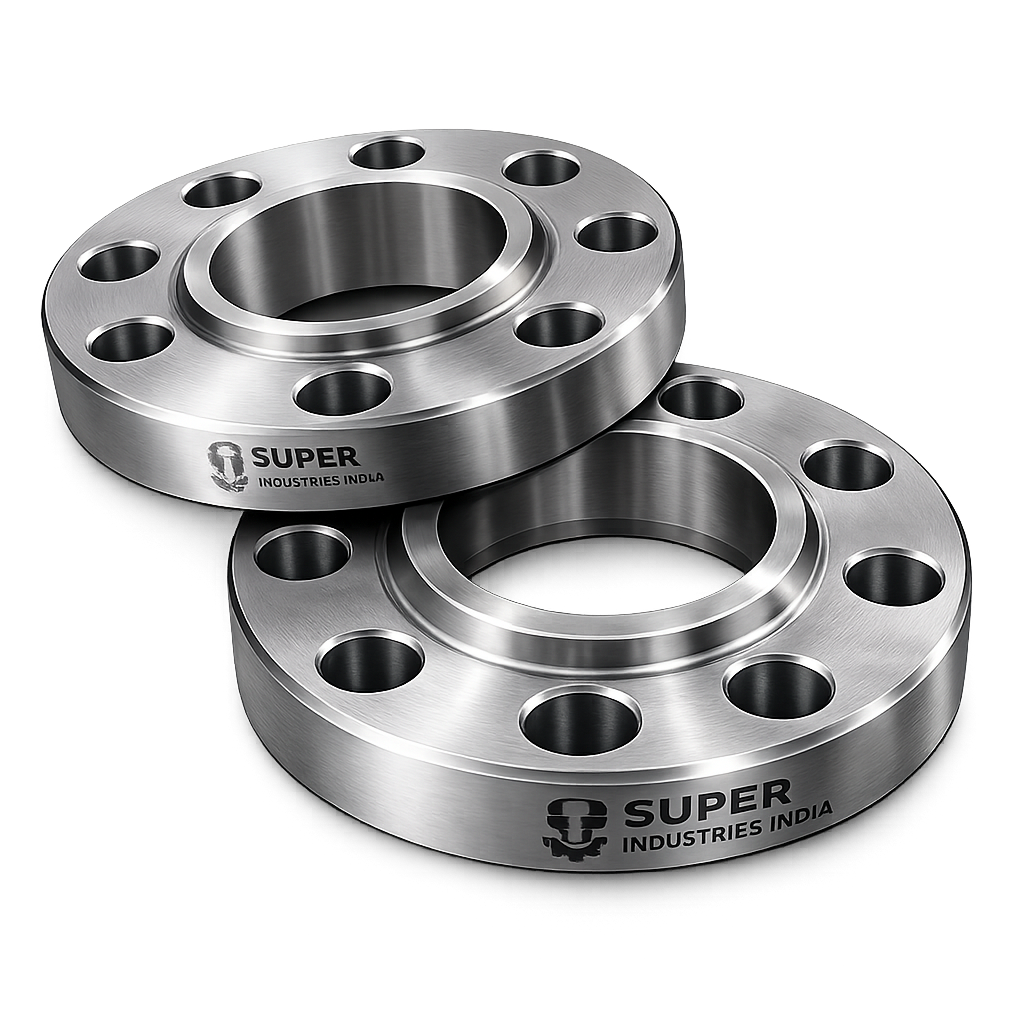
Role of API Flanges in High-Pressure Systems
API Flanges are critical pressure-retaining components used in high-pressure, high-temperature hydrocarbon service environments where joint integrity directly impacts operational safety, environmental protection, and asset reliability.
They are deployed in piping systems, wellhead assemblies, pressure vessels, and flow control equipment, forming detachable mechanical joints capable of withstanding extreme service conditions.
Functional Role in Pressure Systems
In a typical pressurized pipeline or process system:
- Pipe sections, valves, and equipment are connected using flanged joints
- These joints must:
- Maintain leak-tight sealing under pressure
- Resist thermal expansion and contraction
- Withstand mechanical loads and vibration
- Allow controlled disassembly for maintenance
API Flanges are specifically engineered for oil & gas pressure control systems, where standard ASME flanges may not meet pressure or sealing requirements.
Application Across Critical Industries
Upstream Oil & Gas
- Wellhead systems
- Christmas tree assemblies
- Blowout preventers (BOP)
- High-pressure drilling lines
Refineries & Petrochemical Plants
- Hydrocarbon processing units
- Cracking and reforming systems
- High-temperature reactors
Offshore Platforms
- Subsea pipeline connections
- Marine exposure systems
- High-pressure risers
LNG Terminals
- Cryogenic pipelines
- Storage tanks
- Regasification units
Power Generation
- Steam systems
- High-pressure boiler connections
- Turbine piping
Pipeline Infrastructure
- Long-distance crude and gas pipelines
- Pumping and compression stations
Why Flanged Connections Are Preferred
Compared to fully welded or threaded systems, flanged connections provide:
1. Maintainability
- Enables disassembly without cutting or welding
- Reduces downtime during inspection or repair
2. Inspection Accessibility
- Allows internal inspection of piping and equipment
- Facilitates NDT procedures
3. Controlled Sealing Mechanism
- Uses engineered gasket systems
- Enables predictable sealing under defined bolt loads
4. Flexibility Under Load
- Accommodates thermal expansion
- Absorbs vibration and minor misalignment
5. Component Replaceability
- Individual elements (gasket, bolts, flange) can be replaced independently
2. Technical Definition of API Flanges
Definition
API Flanges are pressure-retaining mechanical joints designed for high-pressure oil and gas applications, consisting of:
- Two mating flanges
- A gasket or metal seal
- A set of high-strength bolting
They form a bolted flange connection system that ensures sealing through controlled bolt preload and gasket compression.
Primary Functional Elements
1. Flange Body
- Provides structural rigidity
- Houses bolt holes and sealing face
2. Gasket / Seal Ring
- Provides sealing interface
- Can be soft gasket (RF) or metal ring (RTJ)
3. Bolting System
- Generates preload force
- Maintains joint integrity under pressure
Types of API Flanges
1. Weld Neck Flanges
- Long tapered hub
- Butt-welded to pipe
- Suitable for high pressure and cyclic loading
2. Slip-On Flanges
- Slips over pipe and welded
- Used in lower critical applications
3. Blind Flanges
- No bore
- Used to terminate pipelines
4. Socket Weld Flanges
- Pipe inserted into socket and fillet welded
- Used for small bore, high-pressure lines
5. Threaded Flanges
- Internal threads
- Used where welding is not feasible
API vs ASME Flanges
| Parameter | API Flanges | ASME Flanges |
|---|---|---|
| Primary Use | Oil & Gas high-pressure systems | General industrial piping |
| Pressure Range | 2,000 – 20,000+ PSI | Class 150 – 2500 |
| Sealing Type | Predominantly RTJ | RF / FF / RTJ |
| Standards | API 6A, API 6BX | ASME B16.5, B16.47 |
| Design Focus | Extreme pressure & sealing reliability | General service conditions |
API 6A vs ASME B16.5 / B16.47
API 6A
- Designed for wellhead and Christmas tree equipment
- Includes:
- API 6BX flanges
- RTJ sealing mandatory
- Handles extreme pressures
ASME B16.5
- Covers standard industrial flanges
- Includes RF, FF, RTJ
- Lower pressure range compared to API
Super Industries
Global Manufacturer of Heavy & Custom Engineered Fasteners & Flanges
3. Engineering & Sealing Principle
Fundamental Sealing Mechanism
Sealing in API Flanges is achieved through:
Bolt preload → Gasket compression → Contact stress → Leak prevention
Bolt Preload Mechanics
- Bolts are tightened to induce axial tensile force
- This creates:
- Compressive force across flange faces
- Controlled gasket deformation
Key requirement:
Bolt preload must exceed internal pressure-induced separation force
Gasket Compression Behaviour
Soft Gasket (RF / FF)
- Deforms elastically/plastically
- Fills surface irregularities
RTJ (Ring Type Joint)
- Metal-to-metal sealing
- Ring is plastically deformed into groove
Flange Face Types
1. Raised Face (RF)
- Elevated sealing surface
- Uses soft gasket
2. Flat Face (FF)
- Entire face contacts
- Used in low-pressure systems
3. RTJ (Ring Type Joint)
- Precision-machined groove
- Uses metal ring gasket
Metal-to-Metal Sealing (RTJ)
- Contact occurs at high localized stress
- Ring gasket plastically deforms
- Creates pressure-tight seal without soft material
Critical factors:
- Groove accuracy
- Surface finish
- Ring hardness vs flange hardness
Surface Finish Importance
Surface roughness affects sealing:
| Face Type | Typical Ra Value |
|---|---|
| RF | 3.2 – 6.3 µm |
| RTJ Groove | 1.6 – 3.2 µm |
Too smooth → gasket slip
Too rough → leakage paths
Contact Stress Distribution
Proper sealing requires:
- Uniform bolt tightening
- Even flange face contact
- No localized overstressing
Non-uniform stress leads to:
- Leakage
- Gasket failure
- Bolt relaxation
Pressure & Load Engineering
API Pressure Classes
| API Class | Pressure Rating |
|---|---|
| 2000 | 2,000 PSI |
| 3000 | 3,000 PSI |
| 5000 | 5,000 PSI |
| 10000 | 10,000 PSI |
| 15000 | 15,000 PSI |
| 20000 | 20,000 PSI |
ASME Pressure Classes (Reference)
| Class | Pressure Range |
|---|---|
| 150 | Low pressure |
| 300 | Medium |
| 600 | Moderate |
| 900 | High |
| 1500 | Very high |
| 2500 | Extreme |
Forces Acting on Flanged Joints
1. Internal Pressure Force
Acts to separate flanges.
2. Axial Separation Force

Where:
- (P) = internal pressure
- (A) = internal cross-sectional area
Bolt Load vs Pressure Relationship
To maintain sealing:

Static vs Cyclic Loading
Static Loading
- Constant pressure
- Minimal fatigue concerns
Cyclic Loading
- Pressure fluctuations
- Leads to:
- Bolt fatigue
- Gasket creep
- Loss of preload
Fatigue Resistance
Critical in:
- Offshore systems
- Pulsating pipelines
- Compressor discharge lines
Design considerations:
- Material selection
- Stress concentration reduction
- Controlled preload
Shock Load Conditions
Occur due to:
- Pressure surges
- Valve closures
- Water hammer
API Flanges must:
- Withstand transient loads
- Maintain sealing integrity
4. Dimensional & Design Logic
Key Dimensional Parameters
1. Bolt Circle Diameter (BCD)
- Determines bolt positioning
- Affects load distribution
2. Outer Diameter (OD)
- Structural strength
3. Inner Diameter (ID)
- Matches pipe bore
4. Thickness
- Determines pressure capacity
5. Hub Dimensions
- Provides stress transition
Facing Type Geometry
- RF height
- RTJ groove depth and width
- Surface profile
Tolerance Requirements
Typical controls:
- ±0.5 mm for critical dimensions
- Tight tolerance for RTJ grooves
Alignment Requirements
- Bolt holes must align precisely
- Flange faces must be parallel
Misalignment leads to:
- Uneven gasket compression
- Leakage
Concentricity & Perpendicularity
- Bore must be concentric with flange OD
- Face must be perpendicular to bore axis
These ensure:
- Proper seating
- Uniform load distribution
5. Applicable Standards (API / ASME / ASTM / ISO / EN)
API Flanges are governed by a combination of design standards, dimensional standards, and material specifications, ensuring compatibility across global EPC projects and pressure systems.
API Standards
API 6A
Primary standard for wellhead and Christmas tree equipment, including:
- API flanges up to 20,000 PSI
- Mandatory RTJ sealing configurations
- Strict requirements for:
- Material traceability
- Pressure testing
- Heat treatment qualification
- NDT compliance
API 6BX
Subset within API 6A:
- Designed for high-pressure compact flanges
- Limited bolt configuration
- Metal-to-metal sealing integrity
- Used in:
- Subsea systems
- High-pressure drilling assemblies
ASME Standards
ASME B16.5
- Covers flanges from ½” to 24”
- Pressure classes: 150 to 2500
- Includes:
- RF, FF, RTJ facings
- Dimensional standardization
ASME B16.47
- Covers large diameter flanges (26” to 60”+)
- Series A & Series B configurations
- Used in:
- Pipeline infrastructure
- Large process plants
ASTM Material Standards`
Define chemical composition and mechanical properties:
- ASTM A105 → Carbon steel forgings
- ASTM A350 LF2 → Low-temperature carbon steel
- ASTM A182 → Alloy & stainless steel forgings
ISO Standards
- ISO 7005 → Flange dimensions and pressure ratings
- ISO 15156 → Sour service material compatibility
EN Standards (European Equivalents)
- EN 1092-1 → Flange dimensions
- EN 10222 → Forged steel materials
- EN 10204 → Inspection certification (3.1 / 3.2)
Standards Mapping to Service Conditions
| Standard | Pressure Range | Temperature Range | Application |
|---|---|---|---|
| API 6A | Up to 20,000 PSI | High | Wellhead, drilling |
| ASME B16.5 | Up to Class 2500 | Moderate to high | Process piping |
| ASTM A182 | Material dependent | High temperature | Alloy systems |
| ISO 15156 | Sour service | Controlled | H₂S environments |
6. Material & Grade Options
Material selection for API Flanges is governed by:
- Pressure rating
- Temperature range
- Corrosion environment
- Mechanical loading conditions
Carbon Steel
ASTM A105
- Standard carbon steel forging
- Suitable for:
- Ambient to moderate temperature
- General hydrocarbon service
ASTM A350 LF2
- Low-temperature carbon steel
- Impact-tested
- Used in:
- Sub-zero environments
- LNG systems
Stainless Steel
ASTM A182 F304
- General corrosion resistance
- Moderate strength
ASTM A182 F316
- Enhanced corrosion resistance
- Suitable for:
- Chloride environments
- Marine exposure
Alloy Steel
ASTM A182 F11
- Chromium-molybdenum alloy
- Elevated temperature strength
ASTM A182 F22
- Higher creep resistance
- Used in:
- Power plants
- High-temperature piping
High-Performance Alloys
Duplex Stainless Steel
- High strength + corrosion resistance
- Resistant to stress corrosion cracking
Super Duplex
- Superior chloride resistance
- Offshore applications
Inconel (Nickel Alloys)
- Extreme temperature resistance
- Severe corrosive environments
Material Selection Considerations
| Factor | Requirement |
|---|---|
| Pressure | High yield strength |
| Temperature | Creep resistance |
| Corrosion | Alloy composition |
| Sour Service | H₂S resistance |
Material Comparison Table
| Grade | Yield Strength (MPa) | Tensile Strength (MPa) | Temperature Range | Corrosion Resistance | Typical Application |
|---|---|---|---|---|---|
| ASTM A105 | ~250 | ~485 | -29°C to 425°C | Low | General oil & gas |
| ASTM A350 LF2 | ~250 | ~485 | -46°C to 345°C | Low | Low-temperature service |
| A182 F304 | ~205 | ~515 | Up to 870°C | Moderate | Chemical processing |
| A182 F316 | ~205 | ~515 | Up to 870°C | High | Marine, offshore |
| A182 F11 | ~275 | ~415 | Up to 540°C | Moderate | Power plants |
| A182 F22 | ~415 | ~585 | Up to 600°C | Moderate | High-temp systems |
| Duplex | ~450 | ~620 | Up to 300°C | Very High | Offshore pipelines |
| Super Duplex | ~550 | ~750 | Up to 300°C | Excellent | Subsea systems |
7. Heat Treatment Information
Heat treatment is essential to achieve:
- Required mechanical strength
- Toughness
- Grain refinement
- Stress relief
1. Normalizing
- Heating above critical temperature
- Air cooling
Purpose:
- Refines grain structure
- Improves uniformity
2. Quenching & Tempering
- Rapid cooling (quenching)
- Followed by controlled reheating (tempering)
Purpose:
- High strength
- Controlled hardness
- Improved toughness
3. Solution Annealing (Stainless Steel)
- Heating to high temperature
- Rapid cooling
Purpose:
- Dissolves carbides
- Improves corrosion resistance
4. Stress Relieving
- Heating below transformation temperature
Purpose:
- Removes residual stresses from forging/machining
Hardness Ranges (Typical)
| Material | Hardness (HB) |
|---|---|
| A105 | 120 – 180 |
| LF2 | 130 – 200 |
| F11 / F22 | 150 – 220 |
| Stainless Steel | 150 – 200 |
Impact Testing (Charpy V-Notch)
Required for:
- Low-temperature applications
- API 6A compliance
Ensures:
- Resistance to brittle fracture
- Adequate toughness
8. Manufacturing Process
API Flanges are manufactured through a controlled, traceable, multi-stage process ensuring compliance with pressure-system requirements.
Step 1: Raw Material Inspection
- Chemical composition verification
- Mill Test Certificate (MTC) validation
- Positive Material Identification (PMI)
Step 2: Forging
- Open-die or closed-die forging
- Controlled deformation
Purpose:
- Improves grain flow
- Eliminates internal defects
Step 3: Heat Treatment
- Applied as per material grade
- Controlled furnace conditions
- Temperature recording
Step 4: Rough Machining
- Turning operations
- Removal of excess material
Step 5: CNC Machining
- Precision machining of:
- Bore
- OD
- Bolt holes
- RTJ grooves
Step 6: Facing & Drilling
- Flange face finishing
- Bolt hole drilling with indexing
Step 7: Surface Finishing
- Application of coatings or passivation
- Cleaning and deburring
Step 8: Inspection
- Dimensional verification
- NDT testing
- Hardness checks
Step 9: Marking & Traceability
Each flange marked with:
- Material grade
- Heat number
- Size and rating
- Standard (API / ASME)
Surface Finish Options
Surface finishing is critical for:
- Corrosion protection
- Sealing performance
- Handling durability
Coating Options
Anti-Rust Coating
- Temporary protection during storage
Black Oxide
- Mild corrosion resistance
- Maintains dimensional accuracy
Phosphate Coating
- Improves paint adhesion
- Reduces corrosion
Zinc Plating
- Enhanced corrosion resistance
PTFE Coating
- Chemical resistance
- Low friction
Passivation (Stainless Steel)
- Removes free iron
- Enhances corrosion resistance
Surface Roughness Requirements
| Surface | Roughness (Ra) |
|---|---|
| RF Face | 3.2 – 6.3 µm |
| RTJ Groove | 1.6 – 3.2 µm |
RTJ Groove Finishing
Critical requirements:
- Precision machining
- Burr-free edges
- Controlled hardness compatibility with gasket
A. Dimension Tables (Representative Engineering Reference)
Dimensional values for API Flanges are governed by API 6A / ASME standards. The table below provides a representative engineering reference for typical configurations.
API Flanges – Dimensional Reference Table
| Nominal Size (NPS) | Pressure Class | Flange OD (mm) | BCD (mm) | Bolt Size | No. of Bolts | Thickness (mm) |
|---|---|---|---|---|---|---|
| 2” | 2000 PSI | 165 | 127 | M16 | 4 | 25 |
| 2” | 5000 PSI | 190 | 140 | M20 | 4 | 32 |
| 3” | 5000 PSI | 230 | 178 | M20 | 8 | 38 |
| 4” | 5000 PSI | 280 | 216 | M22 | 8 | 45 |
| 6” | 5000 PSI | 355 | 292 | M24 | 12 | 55 |
| 8” | 5000 PSI | 420 | 349 | M27 | 12 | 65 |
| 10” | 10000 PSI | 510 | 432 | M30 | 16 | 85 |
Engineering Notes:
- BCD (Bolt Circle Diameter) controls load distribution symmetry
- Thickness increases with pressure class to resist bending stress
- Bolt diameter increases with required preload capacity
B. Pressure Rating Table
API Pressure Rating vs MPa
| API Class | Pressure (PSI) | Pressure (MPa) |
|---|---|---|
| 2000 | 2,000 | 13.79 |
| 3000 | 3,000 | 20.68 |
| 5000 | 5,000 | 34.47 |
| 10000 | 10,000 | 68.95 |
| 15000 | 15,000 | 103.42 |
| 20000 | 20,000 | 137.90 |
Temperature Derating Concept
Pressure rating decreases with temperature due to:
- Reduction in material yield strength
- Increased creep deformation
| Temperature (°C) | Strength Reduction Factor |
|---|---|
| 50 | 1.00 |
| 200 | 0.90 |
| 400 | 0.75 |
| 600 | 0.60 |
Engineering Implication:

C. Torque Chart
Bolt torque must generate sufficient preload without exceeding bolt yield strength.
Torque Values (Indicative for B7 Bolting)
| Bolt Size | Torque (Nm) – Lubricated | Torque (Nm) – Dry |
|---|---|---|
| M16 | 120 | 160 |
| M20 | 240 | 320 |
| M22 | 320 | 420 |
| M24 | 450 | 600 |
| M27 | 650 | 850 |
| M30 | 900 | 1200 |
Engineering Considerations
- Lubrication reduces friction → lower torque required
- Torque must be applied in controlled increments
- Over-torque leads to:
- Bolt yielding
- Flange distortion
- Under-torque leads to:
- Leakage
- Gasket failure
D. Preload Calculation Guide
1. Bolt Stress Formula

Where:
- ( \sigma_b ) = Bolt stress
- ( F_b ) = Bolt force
- ( A_b ) = Bolt cross-sectional area
2. Preload Force Formula
Where:
- ( P ) = Internal pressure
- ( A ) = Internal area of pipe
3. Required Bolt Load

4. Sample Calculation
Given:
- Pipe ID = 100 mm
- Pressure = 5,000 PSI (≈ 34.47 MPa)
Step 1: Area

Step 2: Force

Interpretation:
- Total separating force ≈ 270 kN
- Bolt preload must exceed this value
5. Axial Force Requirement
- Must account for:
- Internal pressure
- Gasket seating stress
- External loads
E. Yield Strength Chart (Text Explanation)
Yield strength determines:
- Maximum allowable stress before plastic deformation
- Bolt tightening limits
- Pressure containment capacity
Typical hierarchy:
- Carbon steel < Stainless steel < Alloy steel < Duplex
Higher yield strength enables:
- Higher pressure ratings
- Reduced flange thickness (in optimized design)
F. Mechanical Property Table
| Material | Yield Strength (MPa) | Tensile Strength (MPa) | Hardness (HB) | Elongation (%) | Impact Toughness |
|---|---|---|---|---|---|
| A105 | 250 | 485 | 120–180 | 20 | Moderate |
| LF2 | 250 | 485 | 130–200 | 22 | High (low temp) |
| F304 | 205 | 515 | 150–200 | 30 | High |
| F316 | 205 | 515 | 150–200 | 30 | High |
| F11 | 275 | 415 | 150–220 | 18 | Moderate |
| F22 | 415 | 585 | 170–220 | 16 | Moderate |
G. Corrosion Resistance Table
| Material | Marine | Sour Service (H₂S) | Hydrocarbon | Chemical |
|---|---|---|---|---|
| Carbon Steel | Poor | Limited | Good | Poor |
| SS304 | Moderate | Moderate | Good | Good |
| SS316 | Good | Good | Excellent | Excellent |
| Duplex | Excellent | Excellent | Excellent | Excellent |
| Alloy Steel | Moderate | Limited | Good | Moderate |
9. Inspection & Quality Control Methods
Inspection ensures compliance with:
- API standards
- Project specifications
- Third-party inspection requirements
1. PMI (Positive Material Identification)
- Verifies chemical composition
- Ensures correct material grade
2. UT (Ultrasonic Testing)
- Detects internal defects
- Ensures forging integrity
3. MPI (Magnetic Particle Inspection)
- Surface/subsurface crack detection
- Applicable for ferromagnetic materials
4. DPI (Dye Penetrant Inspection)
- Detects surface cracks
- Used for stainless and non-magnetic materials
5. Hydrostatic Testing
- Pressure testing using water
- Confirms leak-tight integrity
6. Dimensional Inspection
- OD, ID, thickness verification
- Bolt hole alignment checks
- RTJ groove measurement
7. Hardness Testing
- Confirms heat treatment effectiveness
- Ensures compliance with API limits
Third-Party Inspection (TPI)
Conducted by:
- Independent inspection agencies
- Client-appointed inspectors
Certification
- EN 10204 3.1
- Manufacturer test certificate
- EN 10204 3.2
- Third-party verified certificate
Traceability Requirements
Each API flange must be traceable to:
- Heat number
- Material certificate
- Inspection records
- Manufacturing batch
10. Industries Served
API Flanges are deployed in high-integrity pressure systems across multiple capital-intensive industries where containment reliability, inspection accessibility, and compliance with international standards are mandatory.
Oil & Gas Industry
- Wellhead assemblies
- Christmas tree systems
- Blowout preventers (BOP)
- High-pressure drilling manifolds
Upstream (Exploration & Production)
Engineering Requirement:
- API 6A compliance
- High-pressure resistance (10,000–20,000 PSI)
- RTJ sealing integrity
Midstream (Transportation & Storage)
- Crude oil pipelines
- Natural gas transmission systems
- Pumping and compressor stations
Engineering Requirement:
- Fatigue resistance under cyclic pressure
- Leak-tight performance over long distances
- Compatibility with pigging operations
Downstream (Refining & Processing)
- Distillation units
- Cracking and reforming systems
- High-temperature hydrocarbon processing
Engineering Requirement:
- Resistance to thermal expansion
- Corrosion resistance
- High-temperature strength
Petrochemical Industry
- Chemical reactors
- Process piping systems
- Solvent handling systems
Engineering Requirement:
- Chemical compatibility
- Stainless steel or alloy materials
- Controlled sealing performance
LNG Infrastructure
- Cryogenic pipelines
- Storage tanks
- Regasification units
Engineering Requirement:
- Low-temperature toughness (LF2, stainless steel)
- Impact-tested materials
- Leak prevention under thermal contraction
Power Generation
- Boiler piping systems
- Steam lines
- Turbine connections
Engineering Requirement:
- High-temperature strength (F11, F22)
- Creep resistance
- Long-term stability
Offshore & Marine Systems
- Subsea pipelines
- Offshore platforms
- Marine risers
Engineering Requirement:
- Corrosion resistance (SS316, Duplex)
- Fatigue resistance under wave loading
- Compact high-pressure flange designs
Pipeline Infrastructure
- Long-distance pipelines
- Distribution networks
- Terminal stations
Engineering Requirement:
- Standardized dimensions
- Ease of installation and maintenance
- Reliable sealing over extended service life
11. Export Capability & Global Supply
Super Industries operates as a manufacturer and global exporter of API Flanges, supplying to EPC contractors and project owners across multiple regions.
Global Supply Regions
- North America (USA, Canada)
- Europe (EU region)
- Middle East (UAE, Saudi Arabia, Qatar)
- Southeast Asia
- Africa
Export Packaging
Designed to protect dimensional integrity and surface finish:
- Wooden crates (fumigated as per ISPM 15)
- Individual flange protection caps
- Rust-preventive wrapping
- Segregated packing by size and heat number
Documentation Package
Each shipment includes:
- Commercial invoice
- Packing list
- Mill Test Certificates (MTC)
- EN 10204 3.1 / 3.2 certification
- Inspection reports (NDT, dimensional)
- Heat treatment charts
- PMI reports (if required)
Project Logistics Capability
- Bulk supply for EPC projects
- Lot-wise traceability
- Coordination with third-party inspection agencies
- Compliance with project-specific documentation formats
12. Procurement & Installation View
This section reflects field-level engineering practices and EPC installation requirements.
1. Bolt Tightening Sequence
Proper tightening is critical for achieving uniform gasket compression.
Cross-Pattern Tightening
- Bolts are tightened in a star/cross pattern
- Ensures:
- Even load distribution
- Prevention of flange distortion
2. Multi-Stage Tightening Procedure
Typical sequence:
- Initial snug tightening (30% torque)
- Intermediate tightening (60% torque)
- Final tightening (100% torque)
3. Re-Torque Procedure
- Conducted after initial pressurization or temperature stabilization
- Compensates for:
- Gasket creep
- Bolt relaxation
4. Gasket Selection
Selection depends on:
| Parameter | Consideration |
|---|---|
| Pressure | RTJ for high pressure |
| Temperature | Material compatibility |
| Fluid type | Chemical resistance |
| Surface finish | RF vs RTJ compatibility |
5. Installation Inspection Checkpoints
Before installation:
- Verify flange rating and size
- Check RTJ groove condition
- Confirm gasket type and material
- Ensure bolt material compatibility
During installation:
- Ensure alignment of flanges
- Avoid excessive force during fit-up
- Apply lubrication to bolts (if specified)
After installation:
- Torque verification
- Leak testing
- Documentation of installation parameters
6. Storage Conditions
Improper storage affects sealing performance.
Recommended Conditions:
- Dry, covered environment
- Protection from moisture
- RTJ grooves protected with caps
- Segregation by material grade
10. Custom Engineering Capabilities
Super Industries supports project-specific manufacturing requirements aligned with EPC specifications.
1. Non-Standard Sizes
- Custom OD, ID, thickness
- Project-specific dimensional requirements
2. Special Pressure Ratings
- Beyond standard API classes
- Design validation based on load calculations
3. Custom RTJ Groove Profiles
- Special groove geometries
- Compatibility with project-specific ring gaskets
4. Special Coatings
- PTFE coatings
- Anti-corrosion systems
- Offshore-grade protection
5. Project-Specific Markings
- Client tagging systems
- Heat number traceability
- Barcode / QR identification (if required)
Final Engineering Summary
API Flanges function as critical pressure-retaining interfaces in high-pressure piping and wellhead systems. Their performance is governed by:
- Accurate dimensional control
- Proper material selection
- Controlled bolt preload application
- Reliable sealing mechanism (RTJ/RF)
- Compliance with API / ASME / ASTM standards
From an EPC and consultant evaluation perspective, acceptance of an API flange manufacturer depends on:
- Demonstrated understanding of pressure containment mechanics
- Capability to maintain tight dimensional tolerances
- Full compliance with international standards and inspection protocols
- Ability to provide traceable documentation and third-party verification
Conclusion
The engineering design, manufacturing, and application of API Flanges require integration of material science, pressure mechanics, machining precision, and inspection discipline.
For use in critical hydrocarbon and energy infrastructure, API Flanges must consistently deliver:
- Structural integrity under high pressure
- Leak-tight sealing performance
- Compatibility with global standards
- Reliability across the service lifecycle