
BS10 FLANGES
Super Industries
“Global Manufacturer of Heavy & Custom Engineered Fasteners for Oil & Gas, Power & EPC Contractors.”
1. Industry Context & System Relevance
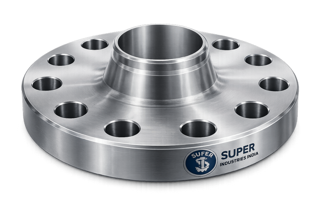
BS10 Flanges are a legacy yet operationally relevant flange system used across low to medium pressure piping networks, particularly in regions and industries influenced by British engineering standards. Their continued use is not incidental—it is driven by installed base compatibility, system continuity, and suitability for moderate-duty service conditions.
Functional Role in Piping Systems
BS10 Flanges provide a detachable mechanical joint for piping systems, enabling:
- Assembly and disassembly for maintenance
- Equipment integration (valves, pumps, strainers)
- Controlled sealing under moderate pressure conditions
- Alignment of piping segments
They are primarily deployed where ease of installation and cost-efficiency outweigh high-pressure performance requirements.
Application Domains
BS10 Flanges are commonly applied in:
Water Treatment Plants
- Raw water intake lines
- Filtration units
- Chemical dosing systems
Marine & Shipbuilding
- Ballast systems
- Cooling water circuits
- Bilge and discharge piping
Fire Protection Systems
- Hydrant lines
- Sprinkler systems
- Pump discharge networks
HVAC Systems
- Chilled water pipelines
- Condenser circuits
- Air handling units
Power Plants (Auxiliary Systems)
- Cooling water lines
- Low-pressure steam drains
- Service water networks
General Industrial Piping
- Utility lines (air, water, low-pressure fluids)
- Process lines with non-critical pressure conditions
Legacy System Relevance
BS10 Flanges are prevalent in:
- Commonwealth countries
- Older infrastructure installations
- Marine vessels built under British classification systems
Their continued use is driven by:
- Interchangeability within existing systems
- Availability of matching components
- Cost-effective replacement strategy
Comparison with ANSI/ASME Systems
| Parameter | BS10 Flanges | ANSI/ASME Flanges |
|---|---|---|
| Pressure Rating | Table-based | Class-based (150, 300, etc.) |
| Sealing Type | Flat Face | Raised Face / RTJ |
| Pressure Range | Low to Moderate | Medium to High |
| Standardization | Dimensional tables | Pressure-temperature ratings |
| Application | Utilities, marine, water | Oil & gas, high pressure systems |
Engineering Note:
BS10 Flanges are not designed for high-pressure or high-temperature applications where ASME B16.5 or B16.47 systems are required.
Pressure & Temperature Suitability
Typical operating conditions:
- Pressure: Up to ~20 bar (depending on table)
- Temperature: Ambient to moderate (~200°C depending on material)
Their suitability is limited by:
- Flat face sealing constraints
- Lower bolt load capacity
- Reduced flange thickness
2. Technical Definition
BS10 Flanges are defined as:
A British Standard flange system where pressure ratings are indirectly defined through dimensional tables (Table A, B, C, D, E, F, H, J, etc.), rather than explicit pressure-temperature ratings.
Table-Based Classification System
Each BS10 table defines:
- Flange outer diameter (OD)
- Bolt circle diameter (PCD)
- Number of bolt holes
- Bolt size
- Flange thickness
Typical Table Hierarchy
| Table | Relative Pressure Capacity |
|---|---|
| A | Very low |
| B | Low |
| C | Low |
| D | Moderate |
| E | Moderate |
| F | Medium |
| H | Medium-high |
| J | Highest within BS10 |
Pressure vs Table Relationship
BS10 does not explicitly define pressure ratings. However, industry approximations exist:
- Table D: ~7–10 bar
- Table E: ~10–16 bar
- Table F: ~16–20 bar
These values depend on:
- Material grade
- Temperature
- Gasket type
- Bolt preload
Flange Type Characteristics
- Face Type: Flat Face (FF)
- Sealing: Gasket-based
- Connection: Bolted joint
- Surface Finish: Smooth or serrated
Super Industries
Global Manufacturer of Heavy & Custom Engineered Fasteners & Flanges
3. Engineering & Sealing Principle
Load Transfer Mechanism
The integrity of a BS10 flange joint is governed by:
- Bolt preload application
- Gasket compression
- Flange face contact
The bolts apply axial force, compressing the gasket between two flat flange faces.
Gasket Compression Theory
The gasket acts as a deformable sealing element:
- Initial compression fills surface irregularities
- Elastic recovery maintains sealing under pressure
- Compression must exceed internal pressure force
Typical gasket types:
- Non-asbestos fiber
- Rubber
- PTFE
Flat Face Sealing Behavior
Unlike raised face flanges:
- Entire flange face is in contact
- Load is distributed uniformly
- Lower stress concentration
However:
- Requires careful alignment
- Sensitive to uneven bolt tightening
Bolt Preload Logic
Bolt preload must:
- Exceed internal pressure force
- Maintain gasket compression
- Prevent joint separation
Key factors:
- Bolt diameter
- Material grade
- Lubrication condition
Leakage Prevention Principles
Leakage is prevented when:
- Gasket stress > internal fluid pressure
- Flange faces remain parallel
- Bolt preload is uniformly distributed
Failure modes include:
- Under-tightening → leakage
- Over-tightening → gasket crushing
- Uneven tightening → flange distortion
4. Pressure & Load Engineering
Static Load Conditions
BS10 Flanges are designed for:
- Internal pressure loading
- Bolt tensile loading
- Gasket compression forces
They are suitable for:
- Steady-state flow systems
- Non-cyclic operations
Dynamic Load Limitations
BS10 Flanges are not recommended for:
- High-frequency pressure fluctuations
- Hydraulic shock systems
- Pulsating loads
Reason:
- Lower flange rigidity
- Reduced bolt load capacity
- Flat face sealing limitations
Stress Limitations
Compared to ANSI/ASME:
- Lower allowable stress
- Reduced safety margins
- No defined pressure-temperature curves
Safety Factor Considerations
Typical design safety approach:
- Conservative table selection
- Oversizing where required
- Material selection based on environment
Unsuitability for High-Pressure Systems
BS10 Flanges should not be used in:
- Hydraulic systems (>20 bar)
- High-temperature steam lines
- Critical oil & gas pipelines
Limitations arise from:
- Flat face design
- Limited bolt preload capacity
- Lack of standardized pressure rating curves
Dimensional & Design Logic
Key Dimensional Parameters
Each BS10 flange includes:
- Outer Diameter (OD)
- Pitch Circle Diameter (PCD)
- Number of Bolt Holes
- Bolt Hole Diameter
- Flange Thickness
- Nominal Bore (NB)
Table-Based Standardization
Dimensions are fixed per table:
- Ensures compatibility within same table
- Prevents cross-table interchangeability
Tolerance Philosophy
- Machining tolerances applied to OD, bore, and PCD
- Bolt hole alignment critical for installation
- Face flatness influences sealing performance
Interchangeability Limitations
- Table D flange ≠ Table E flange
- BS10 ≠ ANSI compatibility
- Requires strict adherence to table designation
Face Design
- Flat Face (FF) standard
- Surface finish affects gasket seating
- No raised face or RTJ provision
5. Applicable Standards
BS10 Flanges are governed by a combination of dimensional standards, material specifications, and inspection protocols. While BS10 defines geometry, it does not independently define material grades or pressure-temperature ratings. Therefore, cross-referencing with other standards is mandatory for EPC-level compliance.
Primary Dimensional Standard
BS10 (British Standard Table of Flanges)
Defines:
- Flange dimensions based on tables (A, B, C, D, E, F, H, J)
- Bolt circle diameter (PCD)
- Number of bolt holes
- Flange thickness
- Nominal bore compatibility
Engineering Implication:
BS10 is a dimensional standard, not a full design code. Pressure capability must be evaluated separately based on material and service conditions.
Relevant International Standards (Cross-Reference)
BS EN 1092-1
- European flange standard replacing older BS systems
- Defines pressure classes (PN6, PN10, PN16, etc.)
- Used for comparison and partial equivalence
Comparison Context:
| BS10 Table | Approximate EN Equivalent |
|---|---|
| Table D | PN6 / PN10 |
| Table E | PN10 / PN16 |
| Table F | PN16 |
Note: Direct interchangeability is not guaranteed due to dimensional differences.
ASTM Material Standards
Material selection for BS10 Flanges is typically aligned with:
- ASTM A105 → Carbon steel forging
- ASTM A350 LF2 → Low-temperature carbon steel
- ASTM A182 F304 / F316 → Stainless steel forgings
DIN / EN Equivalence
- DIN 2573 / 2576 (PN6 / PN10) used for approximate comparison
- EN standards used in export documentation
Engineering Constraint:
Dimensional mismatch prevents direct substitution without verification.
Standard Selection in EPC Projects
Selection depends on:
- Project specification
- Client standardization
- Operating pressure & temperature
- Regional compliance requirements
6. Material & Grade Options
Material selection governs:
- Pressure containment capability
- Corrosion resistance
- Temperature tolerance
- Weldability and machinability
Carbon Steel Grades
ASTM A105
- Forged carbon steel
- Suitable for ambient to moderate temperatures
- Good machinability and strength
ASTM A350 LF2
- Low-temperature carbon steel
- Improved impact resistance
- Suitable for sub-zero applications
Stainless Steel Grades
ASTM A182 F304
- Austenitic stainless steel
- General corrosion resistance
- Suitable for water and mild chemicals
ASTM A182 F316
- Molybdenum-bearing stainless steel
- Enhanced corrosion resistance
- Suitable for marine and chloride environments
Mild Steel (Low-Pressure Applications)
- Used in non-critical systems
- Lower strength compared to forged grades
- Cost-effective for utility lines
Material Comparison Table
| Grade | Yield Strength (MPa) | Tensile Strength (MPa) | Temperature Range (°C) | Corrosion Resistance | Typical Use |
|---|---|---|---|---|---|
| ASTM A105 | ~250 | ~485–620 | -29 to 425 | Low | General industrial piping |
| ASTM A350 LF2 | ~250 | ~485–620 | -46 to 345 | Low | Low-temperature service |
| ASTM A182 F304 | ~205 | ~515–720 | -196 to 870 | Moderate | Water, chemical systems |
| ASTM A182 F316 | ~205 | ~515–720 | -196 to 870 | High | Marine, corrosive fluids |
| Mild Steel | ~200 | ~400–500 | 0 to 300 | Low | Utility pipelines |
7. Heat Treatment Information
Heat treatment is applied to achieve:
- Required mechanical properties
- Grain refinement
- Residual stress reduction
Carbon Steel Heat Treatment
Normalizing
- Refines grain structure
- Improves toughness
- Ensures uniform mechanical properties
Quenching & Tempering (Q&T)
- Increases strength and hardness
- Improves fatigue resistance
Stress Relieving
- Removes residual stresses after machining
- Reduces distortion risk
Stainless Steel Heat Treatment
Solution Annealing
- Heating followed by rapid cooling
- Dissolves carbides
- Restores corrosion resistance
Hardness Ranges
| Material | Typical Hardness (HB) |
|---|---|
| A105 | 120–180 |
| A350 LF2 | 120–180 |
| F304 | 150–200 |
| F316 | 150–200 |
Microstructure Considerations
- Carbon steel: Ferrite-pearlite structure
- Stainless steel: Austenitic structure
These directly influence:
- Strength
- Ductility
- Corrosion resistance
Impact Testing (Charpy V-Notch)
Applicable for:
- Low-temperature service (A350 LF2)
Ensures:
- Resistance to brittle fracture
- Compliance with project specifications
8. Manufacturing Process
BS10 Flanges are produced through controlled and traceable manufacturing processes to ensure dimensional accuracy and material integrity.
Raw Material Inspection
- Verification of mill test certificates
- Chemical composition analysis
- Visual inspection
Forging / Plate Cutting
Forged Flanges:
- Hot forging improves grain flow
- Enhances mechanical strength
Plate-Cut Flanges:
- Used for low-pressure applications
- Machined from steel plates
CNC Machining
- Bore machining
- Outer diameter finishing
- Bolt circle precision machining
Ensures:
- Tight tolerances
- Repeatability
Drilling
- Bolt holes drilled as per PCD
- Angular spacing maintained
- Alignment critical for installation
Facing
- Flat face machining
- Surface finish control
- Ensures proper gasket seating
Heat Treatment (If Required)
- Performed post-forging or machining
- Controlled furnace cycles
Surface Coating
- Anti-corrosion treatment
- Application based on service environment
Final Inspection
- Dimensional verification
- Visual inspection
- NDT (if required)
Marking & Traceability
Each flange marked with:
- Material grade
- Heat number
- Table designation (e.g., Table D, E)
- Manufacturer identification
Ensures:
- Full traceability
- Inspection compliance
Surface Finish Options
Surface condition affects both:
- Corrosion resistance
- Sealing performance
Black Finish
- As-machined or forged surface
- Minimal protection
- Suitable for dry environments
Zinc Plating
- Electroplated coating
- Moderate corrosion protection
- Suitable for indoor applications
Hot-Dip Galvanizing (HDG)
- Thick zinc coating
- High corrosion resistance
- Suitable for outdoor and marine environments
Paint Coating
- Epoxy or industrial coatings
- Applied for project-specific requirements
Stainless Steel Passivation
- Chemical treatment
- Enhances oxide layer
- Improves corrosion resistance
Surface Roughness Consideration
- Affects gasket sealing performance
- Typical Ra values controlled during machining
9. Engineering Tables & Dimensional Data
BS10 Flanges are governed by table-based dimensional standardization, where each table defines a complete geometry set. The following tables represent commonly used configurations for EPC reference and preliminary design validation.
A. BS10 Table Dimension Chart (Representative Values)
Note: Values are indicative for engineering reference. Project-specific drawings and verified standards must be used for procurement.
Table D Flanges (Moderate Pressure – Utility Systems)
| Nominal Bore (NB) | OD (mm) | PCD (mm) | Bolt Size | No. of Holes | Thickness (mm) |
|---|---|---|---|---|---|
| 15 mm | 95 | 65 | M12 | 4 | 10 |
| 25 mm | 115 | 85 | M12 | 4 | 12 |
| 50 mm | 165 | 125 | M16 | 4 | 14 |
| 80 mm | 200 | 160 | M16 | 8 | 16 |
| 100 mm | 220 | 180 | M16 | 8 | 18 |
| 150 mm | 285 | 240 | M20 | 8 | 20 |
| 200 mm | 340 | 295 | M20 | 8 | 22 |
Table E Flanges (Higher Moderate Pressure)
| Nominal Bore (NB) | OD (mm) | PCD (mm) | Bolt Size | No. of Holes | Thickness (mm) |
|---|---|---|---|---|---|
| 15 mm | 95 | 65 | M12 | 4 | 12 |
| 25 mm | 115 | 85 | M12 | 4 | 14 |
| 50 mm | 165 | 125 | M16 | 4 | 16 |
| 80 mm | 200 | 160 | M16 | 8 | 18 |
| 100 mm | 235 | 190 | M20 | 8 | 20 |
| 150 mm | 300 | 250 | M20 | 8 | 22 |
| 200 mm | 360 | 310 | M24 | 8 | 24 |
Table F Flanges (Upper Range of BS10 Capability)
| Nominal Bore (NB) | OD (mm) | PCD (mm) | Bolt Size | No. of Holes | Thickness (mm) |
|---|---|---|---|---|---|
| 25 mm | 115 | 85 | M12 | 4 | 16 |
| 50 mm | 165 | 125 | M16 | 4 | 18 |
| 80 mm | 210 | 170 | M20 | 8 | 20 |
| 100 mm | 250 | 210 | M20 | 8 | 22 |
| 150 mm | 320 | 270 | M24 | 8 | 24 |
| 200 mm | 380 | 330 | M24 | 12 | 26 |
Dimensional Engineering Notes
- Bolt circle (PCD) governs load distribution
- Flange thickness directly impacts bending resistance
- Bolt size correlates with required preload
- Higher tables → increased rigidity and pressure tolerance
B. Pressure Rating Approximation Table
BS10 does not define pressure ratings explicitly. The following table provides engineering approximations for design evaluation.
| BS10 Table | Approx Pressure (Bar) | Approx Pressure (PSI) | Typical Application | Safety Margin Consideration |
|---|---|---|---|---|
| Table D | 7–10 bar | 100–150 psi | Water systems | Moderate |
| Table E | 10–16 bar | 150–230 psi | HVAC / fire systems | Moderate |
| Table F | 16–20 bar | 230–300 psi | Industrial piping | Lower margin |
Engineering Interpretation
- Values depend on material, temperature, and gasket selection
- Safety margins must be validated per project specification
- Not suitable for cyclic or surge pressure systems
C. Torque Chart (Bolt Tightening Reference)
Torque values ensure adequate preload without overstressing bolts or damaging gaskets.
Torque Values (Indicative)
| Bolt Size | Bolt Grade | Dry Torque (Nm) | Lubricated Torque (Nm) |
|---|---|---|---|
| M12 | 8.8 | 70 | 50 |
| M16 | 8.8 | 170 | 120 |
| M20 | 8.8 | 330 | 230 |
| M24 | 8.8 | 570 | 400 |
Torque Engineering Notes
- Lubrication reduces friction → lower torque required
- Over-torque can crush gasket and distort flange
- Under-torque leads to leakage
D. Preload Calculation Guide
Proper preload is critical for maintaining gasket compression and preventing leakage.
Fundamental Bolt Load Formula

Where:
- F = Bolt preload force (N)
- σ = Allowable bolt stress (MPa)
- A = Tensile stress area (mm²)
Torque–Preload Relationship

Where:
- T = Torque (Nm)
- K = Torque coefficient (≈ 0.18–0.25)
- F = Preload force (N)
- d = Bolt diameter (m)
Sample Calculation (M16 Bolt)
Assumptions:
- Bolt stress (σ) = 200 MPa
- Tensile area (A) = 157 mm²
Preload force:
- F = 200 × 157 = 31,400 N
Torque (assuming K = 0.2, d = 0.016 m):
- T = 0.2 × 31,400 × 0.016
- T ≈ 100 Nm
Engineering Considerations
- Preload must exceed internal pressure force
- Gasket seating stress must be maintained
- Safety factor typically applied (1.5–2.5)
E. Mechanical Property Table
| Material | Yield Strength (MPa) | Tensile Strength (MPa) | Elongation (%) | Hardness (HB) |
|---|---|---|---|---|
| ASTM A105 | ~250 | 485–620 | 20–25 | 120–180 |
| ASTM A350 LF2 | ~250 | 485–620 | 22–28 | 120–180 |
| ASTM A182 F304 | ~205 | 515–720 | 30–40 | 150–200 |
| ASTM A182 F316 | ~205 | 515–720 | 30–40 | 150–200 |
Engineering Interpretation
- Higher elongation → better ductility
- Stainless steel → superior corrosion resistance
- Carbon steel → higher load-bearing efficiency
F. Corrosion Resistance Table
| Material | Marine Environment | Water Systems | Industrial Fluids |
|---|---|---|---|
| Carbon Steel | Poor | Moderate | Moderate |
| SS304 | Moderate | Good | Moderate |
| SS316 | Excellent | Excellent | Excellent |
Material Selection Logic
- Marine: SS316 preferred
- Water systems: SS304 acceptable
- General industry: Carbon steel with coating
10. Inspection & Quality Control
Inspection ensures that BS10 Flanges meet:
- Dimensional requirements
- Material specifications
- Mechanical integrity
Positive Material Identification (PMI)
- Verifies chemical composition
- Confirms material grade (CS, SS)
- Required for critical applications
Non-Destructive Testing (NDT)
Ultrasonic Testing (UT)
- Detects internal defects
- Applicable for forged flanges
Magnetic Particle Inspection (MPI)
- Surface crack detection (carbon steel)
Dye Penetrant Inspection (DPI)
- Surface defect detection (stainless steel)
Dimensional Inspection
- OD, PCD, thickness verification
- Bolt hole alignment
- Bore concentricity
Hydrostatic Testing (If Applicable)
- Assembly-level testing
- Verifies sealing performance
- Not typically applied to individual flanges
Hardness Testing
- Confirms heat treatment effectiveness
- Ensures compliance with material standards
Documentation Standards
EN 10204 Certification
- 3.1 Certificate: Manufacturer test certificate
- 3.2 Certificate: Third-party inspection validation
Traceability Requirements
Each flange must maintain:
- Heat number traceability
- Material grade marking
- Table identification (e.g., BS10 Table E)
- Inspection records
Inspection Philosophy
- Prevention over correction
- Batch-level verification
- Compliance with EPC specifications
11. Industries Served
BS10 Flanges are deployed across sectors where moderate pressure, system compatibility, and maintenance accessibility are key design drivers.
Water Treatment & Distribution
Applications include:
- Raw water intake pipelines
- Clarification and filtration systems
- Chemical dosing lines
- Treated water distribution
Engineering Basis:
- Moderate pressure operation
- Compatibility with legacy BS piping systems
- Corrosion protection via coatings or stainless steel
Marine & Shipbuilding
Applications include:
- Ballast water systems
- Sea water cooling lines
- Bilge discharge piping
Material Selection Consideration:
- SS316 for chloride resistance
- Hot-dip galvanized carbon steel for cost-controlled systems
Fire Protection Systems
Applications include:
- Hydrant networks
- Sprinkler systems
- Pump discharge lines
Engineering Requirement:
- Reliable sealing under static pressure
- Compliance with system pressure ratings (typically ≤16 bar)
HVAC & Building Services
Applications include:
- Chilled water lines
- Condenser water systems
- Utility piping networks
Design Consideration:
- Ease of installation and maintenance
- Compatibility with low-pressure systems
Power Plants (Auxiliary Systems)
Applications include:
- Cooling water pipelines
- Service water lines
- Low-pressure steam drains
Engineering Limitation:
- Not used in high-pressure steam circuits
- Restricted to auxiliary and non-critical systems
Infrastructure & General Industry
Applications include:
- Industrial utility lines
- Process water systems
- Non-critical fluid transport
12. Procurement & Installation Engineering View
BS10 Flanges must be evaluated not only as components, but as part of a complete bolted joint system.
Gasket Selection & Placement
- Flat face flanges require full-face gaskets
- Gasket material must match:
- Fluid compatibility
- Temperature range
- Pressure class
Improper gasket selection leads to:
- Leakage
- Premature failure
Bolt Tightening Sequence
A cross-pattern tightening sequence is mandatory to ensure uniform load distribution.
Typical Sequence:
1 → 3 → 5 → 7
2 → 4 → 6 → 8
Engineering Objective:
- Prevent flange distortion
- Achieve uniform gasket compression
Tightening Methodology
- Initial snug tightening
- Incremental torque application (30% → 60% → 100%)
- Final pass for uniformity
Re-Tightening Practice
- Recommended after initial pressurization
- Accounts for gasket relaxation
- Must be performed under controlled conditions
Field Inspection Requirements
Inspection during installation includes:
- Alignment verification
- Bolt torque validation
- Gasket positioning
- Surface cleanliness
Storage & Handling Guidelines
- Store in dry, covered conditions
- Protect flange faces from damage
- Apply rust preventive coatings (if carbon steel)
13. Custom Engineering Capabilities
BS10 Flanges are often adapted to project-specific requirements where standard tables require modification or enhancement.
Dimensional Customization
- Non-standard bolt drilling
- Modified PCD
- Increased flange thickness for higher rigidity
Material Upgrades
- Transition from carbon steel to stainless steel
- Low-temperature service materials
- Corrosion-resistant alloys (project-specific)
Surface Protection Customization
- Project-specific coating systems
- Multi-layer paint coatings
- Enhanced galvanizing thickness
Marking & Identification
- Client-specific tagging
- Heat number traceability
- Project code stamping
Documentation Alignment
- Compliance with EPC specifications
- Integration with inspection plans (ITP)
- Third-party inspection readiness
14. Export Capability
Super Industries supplies BS10 Flanges for international projects with structured export and compliance processes.
Regions Served
- Middle East
- Europe
- Southeast Asia
- Africa
Packaging Standards
- Wooden crates / pallets
- Moisture protection
- Individual tagging for traceability
Export Documentation
Typical documentation includes:
- Commercial invoice
- Packing list
- Mill test certificates (EN 10204 3.1 / 3.2)
- Certificate of origin
- Inspection reports
Logistics & Project Handling
- Batch segregation based on heat number
- Containerized shipment planning
- Coordination with EPC logistics teams
Compliance Documentation
- Material traceability records
- NDT reports
- Dimensional inspection reports
- Coating inspection records
Engineering Limitations & Selection Guidance
BS10 Flanges must be selected with full awareness of their limitations.
Pressure Limitation
- Suitable for low to moderate pressure systems only
- Not recommended beyond ~20 bar
Temperature Limitation
- Material-dependent
- Typically limited to moderate temperatures
Sealing Limitation
- Flat face design requires:
- Accurate alignment
- Proper gasket selection
- Controlled bolt tightening
Dynamic Load Restriction
Not suitable for:
- Pulsating pressure systems
- Hydraulic shock environments
- High vibration pipelines
Interchangeability Restriction
- Not interchangeable with ANSI/ASME flanges
- Not interchangeable across BS10 tables
Engineering Summary
BS10 Flanges represent a dimensionally standardized, table-based flange system engineered for low to medium pressure applications where:
- Flat face sealing is sufficient
- System pressures remain within moderate limits
- Compatibility with existing BS infrastructure is required
Technical Positioning
- Defined by BS10 dimensional tables
- Governed by material standards (ASTM)
- Verified through inspection and testing protocols
- Applied in utility, marine, and general industrial systems
Design Philosophy
- Conservative load handling
- Simplicity in sealing mechanism
- Ease of installation and maintenance
- Compatibility-driven usage
Procurement Perspective
For EPC contractors and consultants, evaluation of BS10 Flanges should include:
- Table selection aligned with pressure requirements
- Material compatibility with service conditions
- Verification of dimensional compliance
- Inspection and certification requirements
Final Engineering Statement
BS10 Flanges are suitable for non-critical, moderate-pressure piping systems where:
- Operational conditions are stable
- Installation practices are controlled
- Design limitations are clearly understood
They are not a substitute for high-pressure flange systems, but remain a relevant and technically viable solution within their defined application envelope.