
DIN FLANGES
Super Industries
“Global Manufacturer of Heavy & Custom Engineered Fasteners for Oil & Gas, Power & EPC Contractors.”
1. Industry Context & System Relevance
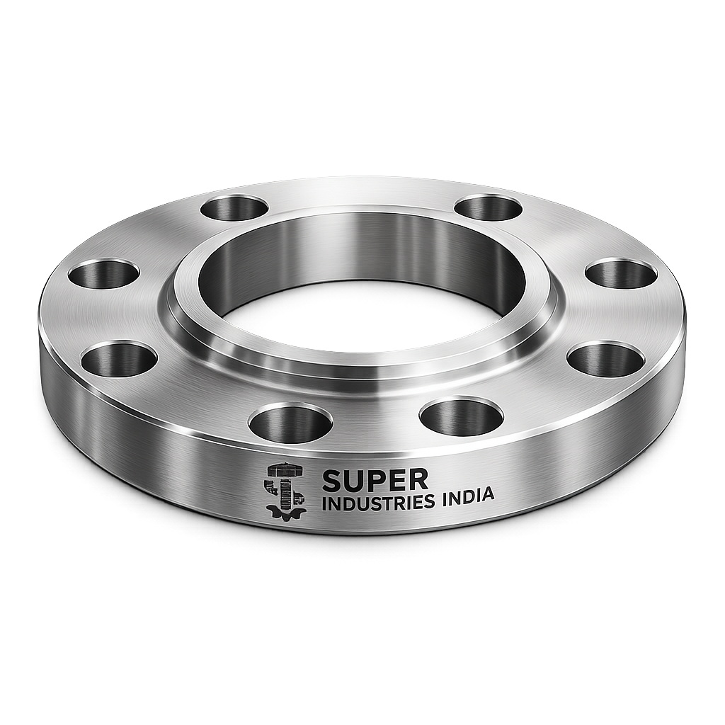
Role of DIN Flanges in Pressure Piping Systems
DIN Flanges serve as mechanical connection interfaces in pressurized piping networks, enabling:
- Assembly and disassembly of piping systems
- Integration of valves, pumps, and equipment
- Inspection, maintenance, and replacement without cutting or welding
They function as pressure boundary components, maintaining system integrity under:
- Internal pressure
- Thermal expansion
- External mechanical loads
Application Across Industrial Sectors
Oil & Gas (Upstream / Midstream / Downstream)
- Pipeline manifolds
- Wellhead connections
- Process skids
- Compressor stations
Refineries & Petrochemical Plants
- High-temperature hydrocarbon lines
- Reactor connections
- Distillation units
Power Generation
- Steam lines (high pressure / high temperature)
- Boiler feedwater systems
- Turbine connections
Chemical Processing Plants
- Corrosive fluid handling
- Acid and solvent pipelines
- Reactor vessels
Water & Wastewater Treatment
- Pumping stations
- Filtration systems
- Municipal pipeline networks
Shipbuilding & Marine Systems
- Ballast systems
- Cooling water circuits
- Fuel transfer lines
Infrastructure & Utility Pipelines
- District cooling
- Irrigation systems
- Industrial utilities
Why Flanged Joints Are Used
Comparison with Welded Joints
| Parameter | Flanged Joint | Welded Joint |
|---|---|---|
| Disassembly | Possible | Not possible |
| Maintenance | Easy | Difficult |
| Installation | Faster (bolting) | Slower (welding + NDT) |
| Leak Risk | Controlled via gasket | Minimal if weld integrity maintained |
| Use Case | Equipment connections | Permanent pipelines |
Conclusion:
Flanges are preferred where periodic maintenance, inspection, or equipment removal is required.
Comparison with Threaded Joints
| Parameter | Flanged Joint | Threaded Joint |
|---|---|---|
| Pressure Capacity | High | Limited |
| Leakage Risk | Controlled via gasket | Higher risk |
| Size Range | Large diameters possible | Limited to small sizes |
| Application | Industrial systems | Low-pressure services |
Conclusion:
Threaded joints are unsuitable for high-pressure, large-diameter, or critical service systems, where DIN Flanges are applied.
2. Technical Definition of DIN Flanges
Fundamental Definition
DIN Flanges are:
- Pressure-retaining bolted joints
- Designed as circular mechanical interfaces
- Manufactured to DIN / EN dimensional standards
- Utilizing gasket-based sealing systems
- Engineered for axial compressive sealing between mating faces
Functional Components of a Flanged Joint
A complete DIN flange connection consists of:
- Two mating flanges
- Gasket (sealing element)
- Bolting system (bolts, nuts, washers)
- Pipe or equipment interface
DIN Flange Types (EN 1092-1 Classification)
1. Weld Neck Flange (Type 11)
- Long tapered hub
- Butt-welded to pipe
- Suitable for:
- High pressure
- High temperature
- Cyclic loading
2. Slip-On Flange (Type 01 / 02)
- Pipe inserted into bore
- Fillet welded (internal + external)
- Used in:
- Moderate pressure systems
- Utility pipelines
3. Blind Flange (Type 05)
- No bore
- Used for:
- Line termination
- Pressure testing
4. Threaded Flange (Type 13)
- Internal threads
- No welding required
- Limited to:
- Low pressure
- Non-critical systems
5. Lap Joint Flange (Type 02 with Stub End)
- Used with stub end
- Allows rotational alignment
- Applied where:
- Frequent dismantling required
- Expensive materials used (stub end only)
Pressure Rating System (PN System)
DIN Flanges are classified using PN (Pressure Nominal) ratings:
| PN Rating | Nominal Pressure (bar) |
|---|---|
| PN6 | 6 bar |
| PN10 | 10 bar |
| PN16 | 16 bar |
| PN25 | 25 bar |
| PN40 | 40 bar |
| PN63 | 63 bar |
| PN100 | 100 bar |
Note:
PN rating is a reference classification, not the actual allowable pressure at all temperatures.
Super Industries
Global Manufacturer of Heavy & Custom Engineered Fasteners & Flanges
3. Engineering & Sealing Principle
Bolt Preload Mechanics
Flange sealing depends on controlled bolt tension.
When bolts are tightened:
- Bolt elongates elastically
- Generates compressive force across flange faces
- Compresses gasket material
This preload must:
- Exceed internal pressure forces
- Maintain sealing under operating conditions
Gasket Compression Behavior
Gaskets function by:
- Filling surface irregularities
- Creating a leak-tight barrier
Critical parameters:
- Seating stress (initial compression)
- Operating stress (maintained during service)
- Recovery capability (ability to rebound under load variation)
Flange Face Types
1. Flat Face (FF)
- Entire surface contacts gasket
- Used in:
- Cast iron systems
- Low-pressure pipelines
2. Raised Face (RF equivalent in EN)
- Elevated sealing surface
- Concentrates load on gasket
- Common in:
- PN16–PN40 systems
3. Tongue & Groove (T&G)
- Interlocking faces
- Provides:
- Improved alignment
- Enhanced sealing
4. Ring Type Joint (RTJ)
- Metal-to-metal sealing with ring gasket
- Used in:
- High-pressure systems
- Critical hydrocarbon services
Surface Finish & Its Impact on Sealing
Surface roughness directly affects gasket performance.
Typical Ra values:
| Gasket Type | Recommended Ra |
|---|---|
| Soft gasket | 3.2 – 6.3 µm |
| Spiral wound | 3.2 – 5.0 µm |
| RTJ | Smooth precision finish |
Too smooth → insufficient grip
Too rough → leakage paths
Sealing Stress vs Internal Pressure
Sealing condition:
Bolt preload ≥ Internal pressure force + safety margin
If:
- Bolt load decreases (relaxation, temperature)
- Internal pressure increases
→ Leakage may occur
Leakage Prevention Theory
Leak-free performance depends on:
- Proper gasket selection
- Correct bolt preload
- Uniform load distribution
- Controlled surface finish
- Flange rigidity
4. Pressure & Load Engineering
PN Rating vs Actual Pressure-Temperature Relationship
PN rating is defined at reference temperature (typically 20°C).
As temperature increases:
- Material strength decreases
- Allowable pressure reduces
This requires temperature derating based on material standards.
Static vs Cyclic Loading
Static Loading
- Constant internal pressure
- Minimal stress variation
Cyclic Loading
- Pressure fluctuations
- Thermal cycles
- Causes:
- Fatigue
- Bolt loosening
- Gasket degradation
Thermal Expansion Stress
Pipelines expand due to temperature:

This induces:
- Axial forces
- Bending moments at flanges
Pipeline Bending Stress
Misalignment or external loads generate:
- Bending stress at flange interface
- Uneven gasket compression
- Potential leakage
Fatigue Loading
Repeated stress cycles may cause:
- Bolt fatigue failure
- Crack initiation in flange hub
- Loss of preload
Bolt Load vs Gasket Seating Stress
Two critical conditions:
- Initial Seating Condition
- Sufficient stress to compress gasket
- Operating Condition
- Maintain stress despite pressure and temperature
Safety Factor Philosophy
Engineering design incorporates:
- Material safety factors
- Bolt load margins
- Gasket stress margins
To ensure:
- Leak-free performance
- Structural integrity
- Long-term reliability
Dimensional & Design Logic
Key Geometrical Parameters
1. Bolt Circle Diameter (PCD)
- Determines bolt load distribution
- Must align precisely with mating flange
2. Number of Bolt Holes
- Increases with:
- Diameter
- Pressure rating
3. Flange Thickness
- Provides structural rigidity
- Prevents rotation under load
4. Hub Dimensions (Weld Neck Flange)
- Tapered hub reduces stress concentration
- Improves fatigue resistance
5. Facing Dimensions
- Defines gasket seating area
- Must comply with EN tolerances
Tolerance Requirements (EN Standards)
Controlled parameters:
- Flatness
- Parallelism
- Concentricity
- Bore tolerance
These ensure:
- Proper alignment
- Uniform gasket compression
Surface Roughness
Specified in Ra (µm)
Critical for:
- Gasket sealing
- Frictional grip
Geometric Accuracy Requirements
| Parameter | Importance |
|---|---|
| Flatness | Prevent leakage |
| Parallelism | Uniform load |
| Concentricity | Alignment |
| Surface finish | Seal integrity |
5. Applicable Standards (CORE SECTION)
DIN EN 1092-1 (Primary Governing Standard)
DIN Flanges are primarily manufactured in accordance with:
DIN EN 1092-1 — Flanges and their joints — Circular flanges for pipes, valves, fittings and accessories, PN designated
This standard defines:
- Flange types (Type 01, 02, 05, 11, 13, etc.)
- PN pressure ratings
- Dimensional requirements (DN sizes, PCD, thickness)
- Facing types and surface finish
- Tolerances and permissible deviations
- Marking and identification requirements
It serves as the primary dimensional and pressure reference for DIN flange systems across Europe and international EPC projects.
DIN Legacy Standards (Pre-EN Harmonization)
Prior to EN standardization, DIN flanges were governed by individual standards:
| DIN Standard | Description |
|---|---|
| DIN 2501 | General flange dimensions |
| DIN 2573 | PN6 plate flanges |
| DIN 2576 | PN10 plate flanges |
| DIN 2633 | PN16 weld neck flanges |
| DIN 2635 | PN40 weld neck flanges |
Engineering Relevance:
- Still referenced in brownfield projects
- Used in replacement and retrofit systems
- Dimensional equivalence is often required during project execution
EN 1759 (Class-Designated Flanges)
EN 1759 introduces Class-based flanges aligned with ASME systems:
- Class 150
- Class 300
- Class 600
Used when:
- Projects require compatibility with ASME-based systems
- Hybrid specifications exist (EN + ASME)
ASTM Material Standards (Material Compliance)
DIN Flanges use materials compliant with ASTM standards for global acceptance:
| Material Type | ASTM Standard |
|---|---|
| Carbon Steel | ASTM A105 |
| Low Temperature CS | ASTM A350 LF2 |
| Stainless Steel | ASTM A182 |
| Alloy Steel | ASTM A182 F11 / F22 |
These define:
- Chemical composition
- Mechanical properties
- Heat treatment requirements
ISO Standards (Supplementary Alignment)
ISO standards provide:
- General dimensional harmonization
- Inspection and testing frameworks
- Quality management alignment
Comparison: DIN PN vs ASME Class
Approximate equivalence used for global project referencing:
| DIN PN Rating | Approx. ASME Class |
|---|---|
| PN6 | Class 150 (lower range) |
| PN10 | Class 150 |
| PN16 | Class 150 |
| PN25 | Class 300 |
| PN40 | Class 300 |
| PN63 | Class 600 |
| PN100 | Class 600+ |
Important Engineering Note:
- This is not a direct substitution
- Pressure-temperature ratings differ
- Material group and temperature must be verified before interchange
6. Material & Grade Options
Material selection for DIN Flanges is governed by:
- Pressure requirements
- Temperature range
- Corrosion environment
- Fluid characteristics
Carbon Steel Grades
ASTM A105
- Standard forging grade
- Used for:
- Ambient to moderate temperature systems
- Oil & gas pipelines
P250GH (EN 10222)
- European pressure vessel steel
- Suitable for:
- Elevated temperature service
- Boiler and pressure systems
Low Temperature Carbon Steel
ASTM A350 LF2
- Designed for sub-zero applications
- Impact tested (Charpy V-notch)
- Used in:
- LNG systems
- Cold climate pipelines
Stainless Steel Grades
ASTM A182 F304 / F304L
- General corrosion resistance
- Suitable for:
- Water systems
- Chemical service (non-chloride)
ASTM A182 F316 / F316L
- Enhanced corrosion resistance
- Molybdenum addition improves:
- Chloride resistance
- Pitting resistance
Duplex Stainless Steel
F51 / F60
- Dual-phase microstructure
- High strength + corrosion resistance
- Used in:
- Offshore platforms
- Seawater systems
Alloy Steel Grades
F11 / F22
- Chromium-molybdenum steels
- High temperature strength
- Used in:
- Power plants
- Steam systems
Material Comparison Table
| Grade | Yield Strength (MPa) | Tensile Strength (MPa) | Temperature Range | Corrosion Resistance | Typical Applications |
|---|---|---|---|---|---|
| ASTM A105 | ~250 | 485–620 | -20°C to 425°C | Low | Oil & gas pipelines |
| P250GH | ~250 | 410–540 | Up to 450°C | Moderate | Pressure vessels |
| ASTM A350 LF2 | ~250 | 485–620 | Down to -46°C | Low | LNG, low-temp service |
| F304 | ~205 | 515–720 | -196°C to 425°C | Good | Water, chemicals |
| F316 | ~205 | 515–720 | -196°C to 550°C | Very good | Marine, chlorides |
| Duplex F51 | ~450 | 620–880 | -50°C to 300°C | Excellent | Offshore |
| F11 | ~275 | 415–585 | Up to 540°C | Moderate | Steam lines |
| F22 | ~415 | 585–760 | Up to 600°C | Moderate | High-temp power |
Material Selection Logic
| Condition | Recommended Material |
|---|---|
| High pressure, ambient temp | A105 |
| Low temperature | A350 LF2 |
| Corrosive environment | F316 |
| Marine / offshore | Duplex F51 |
| High temperature steam | F11 / F22 |
7. Heat Treatment Information
Heat treatment ensures:
- Required mechanical properties
- Grain refinement
- Stress relief
Normalizing
- Heating above critical temperature
- Air cooling
Effect:
- Refines grain structure
- Improves toughness
Quenching & Tempering
- Rapid cooling (quenching)
- Controlled reheating (tempering)
Effect:
- Increased strength
- Controlled hardness
Used for:
- Alloy steel flanges
Solution Annealing (Stainless Steel)
- Heating to high temperature
- Rapid quenching
Effect:
- Dissolves carbides
- Improves corrosion resistance
Stress Relieving
- Heating below transformation temperature
Purpose:
- Remove residual stresses from:
- Forging
- Machining
Grain Structure Control
Critical for:
- Fatigue resistance
- Impact strength
- Structural integrity
Impact Testing (Charpy V-Notch)
Required for:
- Low-temperature applications
Measures:
- Energy absorption during fracture
Hardness Ranges (Typical)
| Material | Hardness (HB) |
|---|---|
| A105 | 120–187 |
| LF2 | 120–200 |
| F11/F22 | 150–220 |
| Stainless Steel | 140–200 |
8. Manufacturing Process
DIN Flanges are manufactured through a controlled sequence ensuring compliance with dimensional and material standards.
1. Raw Material Verification
- Mill Test Certificate (MTC) verification
- Chemical composition check
- Heat number traceability
2. Forging Process
Open Die Forging
- Used for:
- Large diameter flanges
- Custom sizes
Closed Die Forging
- Used for:
- Standard sizes
- High repeatability
Engineering Benefit:
- Improved grain flow
- Enhanced mechanical strength
3. Rough Machining
- Removal of excess material
- Preparation for final machining
4. CNC Finish Machining
- Precision machining of:
- Bore
- Facing
- Bolt holes
Ensures:
- Tight tolerances
- Surface finish compliance
5. Facing & Drilling
- Serrated or smooth finish applied
- Bolt holes drilled as per PCD
6. Heat Treatment
Performed as per:
- Material specification
- Project requirement
7. Surface Coating
Based on service conditions:
- Anti-corrosion protection
- Temporary storage protection
8. Final Inspection
Includes:
- Dimensional verification
- Surface finish inspection
- NDT (if required)
9. Marking & Traceability
Each DIN flange is marked with:
- Standard (DIN EN 1092-1)
- Material grade
- DN size
- PN rating
- Heat number
- Manufacturer identification
Surface Finish Options
Protective Coatings
| Finish Type | Application |
|---|---|
| Anti-rust oil | Temporary protection |
| Black painting | General industrial use |
| Zinc plating | Corrosion resistance |
| Hot-dip galvanizing | Outdoor / marine |
| PTFE coating | Chemical resistance |
| Passivation (SS) | Corrosion resistance |
| Shot blasting | Surface cleaning |
Facing Surface Finish (Critical)
| Finish Type | Ra Value (µm) | Application |
|---|---|---|
| Smooth finish | ≤ 3.2 | Metal gaskets |
| Serrated finish | 3.2 – 6.3 | Soft gaskets |
| RTJ groove finish | Precision machined | High-pressure systems |
Engineering Importance
Surface finish affects:
- Gasket seating
- Frictional resistance
- Leak prevention
A. DIN Flange Dimension Tables (Representative – EN 1092-1)
The following tables provide indicative dimensional data for commonly used DIN Flanges. Final dimensions must always be verified against DIN EN 1092-1 based on flange type and facing.
PN16 DIN Flange Dimensions (Type 11 / Type 01 – Representative)
| DN (mm) | Flange OD (mm) | Thickness (mm) | PCD (mm) | Bolt Size | No. of Bolts |
|---|---|---|---|---|---|
| 15 | 95 | 14 | 65 | M12 | 4 |
| 25 | 115 | 16 | 85 | M12 | 4 |
| 50 | 165 | 18 | 125 | M16 | 4 |
| 80 | 200 | 20 | 160 | M16 | 8 |
| 100 | 220 | 22 | 180 | M16 | 8 |
| 150 | 285 | 24 | 240 | M20 | 8 |
| 200 | 340 | 26 | 295 | M20 | 12 |
| 300 | 460 | 28 | 410 | M20 | 12 |
PN40 DIN Flange Dimensions (Representative)
| DN (mm) | Flange OD (mm) | Thickness (mm) | PCD (mm) | Bolt Size | No. of Bolts |
|---|---|---|---|---|---|
| 15 | 95 | 16 | 65 | M12 | 4 |
| 25 | 115 | 18 | 85 | M12 | 4 |
| 50 | 165 | 20 | 125 | M16 | 4 |
| 80 | 200 | 24 | 160 | M16 | 8 |
| 100 | 235 | 26 | 190 | M20 | 8 |
| 150 | 300 | 30 | 250 | M20 | 8 |
| 200 | 375 | 34 | 320 | M24 | 12 |
| 300 | 515 | 40 | 450 | M24 | 16 |
Dimensional Engineering Notes
- PCD (Pitch Circle Diameter) governs bolt load distribution
- Increasing PN rating → higher thickness & bolt size
- Bolt quantity increases to maintain uniform gasket compression
- Weld neck flanges include additional hub geometry (not shown in table)
B. Pressure Rating Table (PN System)
Nominal Pressure vs Actual Pressure
| PN Rating | Pressure (bar) | Pressure (MPa) |
|---|---|---|
| PN6 | 6 | 0.6 |
| PN10 | 10 | 1.0 |
| PN16 | 16 | 1.6 |
| PN25 | 25 | 2.5 |
| PN40 | 40 | 4.0 |
| PN63 | 63 | 6.3 |
| PN100 | 100 | 10.0 |
Temperature Derating Concept
Actual allowable pressure is a function of:
- Material strength at temperature
- Design safety factor
Example (Carbon Steel A105)
| Temperature (°C) | Allowable Pressure (% of PN) |
|---|---|
| 20°C | 100% |
| 200°C | ~85% |
| 300°C | ~70% |
| 400°C | ~50% |
Engineering Interpretation
- PN rating is not constant across temperature
- High temperature → reduced allowable pressure
- Material selection must align with pressure-temperature envelope
C. Torque Chart
Bolt tightening torque ensures required preload for sealing.
Torque Values (Indicative – Lubricated vs Dry)
| Bolt Size | Grade | Torque (Nm) Lubricated | Torque (Nm) Dry |
|---|---|---|---|
| M12 | 8.8 | 70 | 90 |
| M16 | 8.8 | 170 | 220 |
| M20 | 8.8 | 330 | 420 |
| M24 | 8.8 | 570 | 720 |
| M30 | 8.8 | 1100 | 1400 |
| M20 | 10.9 | 470 | 600 |
| M24 | 10.9 | 800 | 1000 |
| M30 | 10.9 | 1500 | 1900 |
| 3/4” | B7 | 250 | 320 |
| 1” | B7 | 500 | 650 |
| 1-1/4” | B7 | 900 | 1150 |
Torque Engineering Notes
- Lubrication reduces friction → lower torque required
- Dry tightening increases variability
- Torque must align with:
- Bolt grade
- Gasket type
- Flange rating
D. Preload Calculation Guide
Bolt Stress Formula

Where:
- σ = Bolt stress (MPa)
- F = Applied force (N)
- A = Bolt cross-sectional area (mm²)
Preload Force Formula

Torque–Preload Relationship

Where:
- T = Torque (Nm)
- K = Torque coefficient (≈ 0.18–0.25)
- F = Preload (N)
- d = Nominal bolt diameter (m)
Sample Calculation
Given:
- Bolt: M20 (Area ≈ 245 mm²)
- Target stress: 200 MPa
Step 1: Preload Force
F = 200 × 245 = 49,000 N
Step 2: Torque Calculation
Assume:
- K = 0.2
- d = 0.02 m
T = 0.2 × 49,000 × 0.02 = 196 Nm
Gasket Seating Stress
Gasket requires:
- Minimum seating stress
- Maintained stress during operation
Typical values:
| Gasket Type | Seating Stress (MPa) |
|---|---|
| Soft gasket | 10–30 |
| Spiral wound | 50–100 |
| RTJ | 150+ |
Safety Margin
Preload must account for:
- Relaxation
- Temperature variation
- Pressure fluctuations
Engineering practice:
Apply 1.5–2.0 safety factor on required gasket stress
E. Mechanical Property Table
| Material | Yield Strength (MPa) | Tensile Strength (MPa) | Elongation (%) | Hardness (HB) | Impact (J) |
|---|---|---|---|---|---|
| A105 | 250 | 485–620 | 20 | 120–187 | Not mandatory |
| LF2 | 250 | 485–620 | 22 | 120–200 | ≥ 27 J @ -46°C |
| F304 | 205 | 515–720 | 30 | ≤ 200 | High |
| F316 | 205 | 515–720 | 30 | ≤ 200 | High |
| Duplex F51 | 450 | 620–880 | 25 | ≤ 290 | High |
| F11 | 275 | 415–585 | 20 | 150–220 | Moderate |
| F22 | 415 | 585–760 | 18 | 150–220 | Moderate |
F. Corrosion Resistance Table
| Material | Marine | Acidic | High Humidity | Hydrocarbon |
|---|---|---|---|---|
| Carbon Steel | Poor | Poor | Moderate | Good |
| SS304 | Moderate | Moderate | Good | Good |
| SS316 | Good | Good | Excellent | Good |
| Duplex F51 | Excellent | Excellent | Excellent | Excellent |
| Alloy Steel | Poor | Poor | Moderate | Excellent |
Engineering Interpretation
- Carbon steel requires coating in corrosive environments
- SS316 preferred for chloride exposure
- Duplex used for combined strength + corrosion resistance
9. Inspection & Quality Control Methods
Material Verification
PMI (Positive Material Identification)
- Confirms alloy composition
- Ensures correct grade
Non-Destructive Testing (NDT)
Ultrasonic Testing (UT)
- Detects internal flaws
Magnetic Particle Inspection (MPI)
- Surface crack detection (ferromagnetic materials)
Dye Penetrant Inspection (DPI)
- Surface defects (non-magnetic materials)
Dimensional Inspection
Verification of:
- OD, ID
- Thickness
- PCD
- Bolt hole alignment
Using:
- Vernier calipers
- CMM (Coordinate Measuring Machine)
Hydro Testing (Assembly Level)
- Applied when flange is part of assembled system
- Verifies:
- Leak-tightness
- Structural integrity
Hardness Testing
- Confirms heat treatment effectiveness
- Ensures compliance with material standards
Third-Party Inspection
Conducted by:
- Independent inspection agencies
Scope includes:
- Dimensional verification
- Material validation
- Documentation review
Certification
EN 10204 3.1
- Manufacturer test certificate
EN 10204 3.2
- Third-party validated certificate
Traceability Requirements
Each DIN flange is traceable through:
- Heat number
- Material batch
- Inspection records
10. Industries Served
DIN Flanges are deployed across multiple sectors where pressure integrity, maintainability, and standardization are required.
Oil & Gas Industry
Upstream
- Wellhead connections
- Flowlines
- Gathering systems
Midstream
- Transmission pipelines
- Pumping stations
- Metering skids
Downstream
- Refinery process units
- Storage terminals
- Loading/unloading systems
Engineering Requirements:
- High pressure capability
- Resistance to hydrocarbons
- Compliance with inspection standards
Refineries & Petrochemical Plants
Applications include:
- Distillation columns
- Heat exchangers
- Reactor piping systems
Key Considerations:
- Elevated temperatures
- Corrosive process fluids
- Cyclic operating conditions
Power Generation
Thermal Power Plants
- Steam lines (high temperature / high pressure)
- Boiler connections
Combined Cycle Plants
- Gas turbine auxiliaries
- Cooling water systems
Nuclear (Non-safety Class Applications)
- Auxiliary piping systems
Engineering Focus:
- Thermal fatigue resistance
- Alloy steel material selection (F11 / F22)
Chemical Processing Industry
Used in:
- Acid handling pipelines
- Solvent systems
- Process reactors
Material Selection Priority:
- Stainless steel (F316 / F316L)
- Duplex stainless steel
Water & Wastewater Systems
Applications:
- Pumping stations
- Treatment plants
- Distribution networks
Requirements:
- Corrosion resistance
- Cost-effective material selection
- Long service life
Marine & Shipbuilding
Used in:
- Ballast systems
- Cooling water circuits
- Fuel systems
Critical Factors:
- Saltwater corrosion
- Vibration and fatigue resistance
Infrastructure & Utility Pipelines
Includes:
- District cooling
- Irrigation systems
- Industrial utilities
Focus:
- Standardization
- Ease of installation and maintenance
11. Export Capability & Global Supply
Super Industries supplies DIN Flanges aligned with international EPC procurement frameworks.
Export Regions
Europe
- Compliance with DIN EN 1092-1 mandatory
- Documentation and traceability critical
Middle East
- Oil & gas and infrastructure projects
- Third-party inspection requirements
Southeast Asia
- Power and chemical industries
- Mixed DIN / ASME project specifications
United States (Project-Based Supply)
- Supplied under equivalence evaluation
- DIN to ASME compatibility review required
Packaging Standards
- Wooden crates (ISPM-15 compliant)
- Moisture protection wrapping
- Anti-corrosion coating before dispatch
Export Documentation
Provided documentation includes:
- Commercial invoice
- Packing list
- Mill Test Certificates (EN 10204 3.1 / 3.2)
- Inspection reports
- Country of origin certificate
Project Logistics
- Batch-wise traceability maintained
- Segregation by:
- Size (DN)
- PN rating
- Material grade
- Coordination with:
- Freight forwarders
- EPC logistics teams
Compliance Documentation
- Material certificates
- Heat treatment records
- NDT reports
- Dimensional inspection reports
11. Procurement & Installation View
This section aligns with site-level execution requirements for EPC contractors.
Bolt Tightening Sequence
Correct tightening ensures uniform gasket compression.
Cross Pattern Tightening
Typical sequence:
1 → 3 → 5 → 7 → 2 → 4 → 6 → 8
Engineering Outcome:
- Even load distribution
- Reduced flange distortion
Torque Control Procedure
- Initial snug tightening
- Intermediate torque (50%)
- Final torque (100%)
- Verification pass
Gasket Installation Guidelines
- Ensure clean flange faces
- Align gasket centrally
- Avoid reuse of gaskets
- Select gasket based on:
- Pressure
- Temperature
- Fluid compatibility
Re-Torque Practices
Required when:
- High temperature operation
- Gasket relaxation expected
Performed:
- After initial pressure cycle
- At ambient condition (if applicable)
Inspection Checkpoints (Site)
- Flange face condition
- Bolt grade verification
- Torque value confirmation
- Alignment and parallelism
Storage Conditions
- Dry, covered storage
- Protection from:
- Moisture
- Dust
- Mechanical damage
- Use of:
- End protectors
- Anti-rust coatings
12. Custom Engineering Capabilities
Super Industries supports project-specific DIN Flanges beyond standard catalog dimensions.
Non-Standard DN Sizes
- Large diameter flanges
- Project-specific pipeline requirements
Special Drilling Patterns
- Custom bolt hole configurations
- Interface compatibility with existing systems
Increased Thickness / Reinforced Designs
- Higher pressure applications
- Structural reinforcement for:
- Bending loads
- External forces
Special Coatings
- PTFE for chemical resistance
- Epoxy coatings for buried service
- Galvanizing for marine exposure
Project Marking & Identification
- Client-specific stamping
- Tag numbers
- Heat traceability integration
Final Engineering Conclusion
DIN Flanges are standardized pressure-retaining components designed to provide:
- Reliable sealing under controlled bolt preload
- Dimensional compatibility across global systems
- Maintainability through bolted connections
Their performance depends on:
- Correct material selection
- Compliance with DIN EN 1092-1
- Controlled manufacturing processes
- Proper installation and torque application
For EPC and capital projects, DIN Flanges must be evaluated based on:
- Pressure-temperature ratings
- Mechanical properties
- Inspection and certification compliance
- Dimensional accuracy and tolerance control
Super Industries manufactures DIN Flanges aligned with:
- DIN / EN standards
- International material specifications
- Inspection and traceability requirements
This enables integration into:
- Oil & gas systems
- Power generation facilities
- Chemical processing plants
- Infrastructure pipelines
Where pressure integrity, compliance, and maintainability are mandatory engineering requirements.