
ASME FLANGES
“Global Manufacturer of Heavy & Custom Engineered Fasteners for Oil & Gas, Power & EPC Contractors.”
1. Industry Context & System Relevance
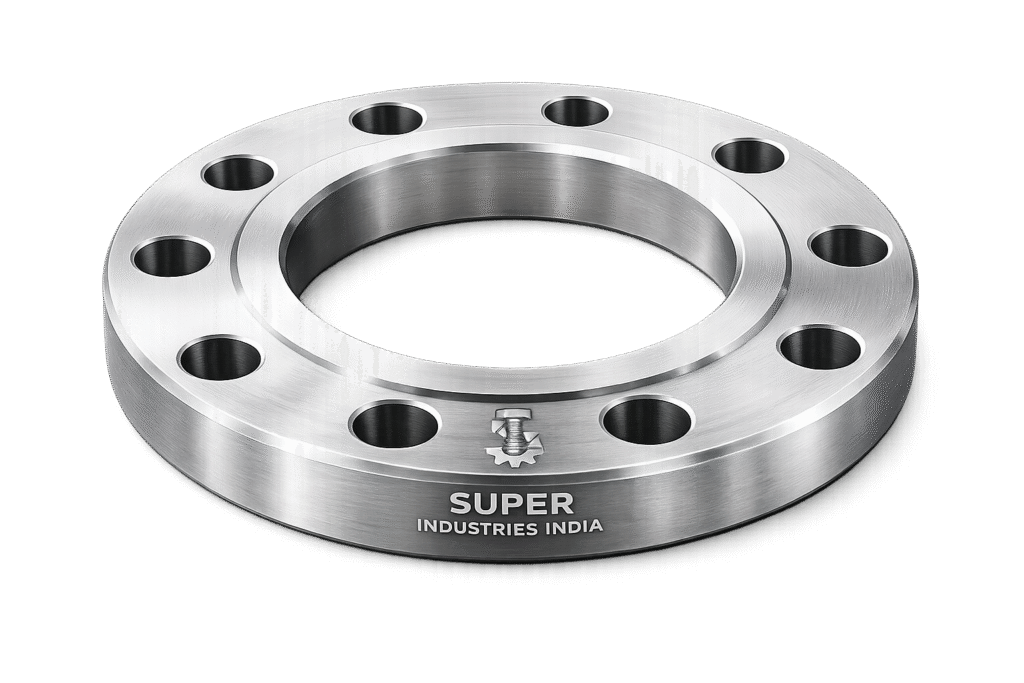
ASME flanges form a fundamental component of pressure-containing piping systems used across capital-intensive industrial infrastructure. These components provide a mechanically detachable connection between pipes, valves, pressure vessels, and rotating equipment, while maintaining pressure boundary integrity under defined operating conditions.
Role of ASME Flanges in Piping Systems
In engineered piping systems designed per ASME codes (notably B31.3 and Section VIII), flanges serve the following critical functions:
- Mechanical joining of piping components
- Facilitating periodic maintenance and inspection
- Allowing equipment isolation without cutting/welding
- Maintaining leak-tight pressure boundaries under load
- Providing flexibility in modular system design
Unlike permanent welded joints, flanged connections enable controlled disassembly, making them indispensable in systems requiring:
- Frequent inspection (e.g., refinery units)
- Equipment replacement (e.g., pumps, exchangers)
- Process cleaning (e.g., chemical reactors)
Industrial Applications
ASME flanges are deployed across a wide spectrum of industrial sectors:
Oil & Gas
- Upstream gathering lines
- Midstream transmission pipelines
- Downstream refinery units
Refineries
- Distillation columns
- Heat exchangers
- Reactor feed systems
Power Generation
- Boiler piping systems
- Steam headers
- Turbine inlet/outlet connections
LNG Terminals
- Cryogenic piping systems
- Storage tank connections
Petrochemical Plants
- High-pressure reactors
- Polymer processing units
Offshore Platforms
- Compact piping layouts
- High vibration and cyclic loading environments
Chemical Processing
- Corrosive fluid transport
- Acid handling systems
Flanged vs Welded vs Threaded Connections
| Parameter | Flanged Joint | Welded Joint | Threaded Joint |
|---|---|---|---|
| Disassembly | Yes | No | Limited |
| Leak Integrity | High (with gasket) | Very High | Moderate |
| Maintenance | Easy | Difficult | Moderate |
| Installation Complexity | Medium | High | Low |
| Pressure Capability | High | Very High | Low–Moderate |
| Inspection Access | Excellent | Limited | Limited |
Why Flanged Joints Are Preferred
Flanged joints are selected over welded joints when:
- System requires periodic disassembly
- Equipment needs frequent replacement
- Inspection access is mandated by codes
- Thermal expansion requires flexible connection interfaces
They are preferred over threaded joints in:
- High-pressure systems
- Large diameter pipelines
- Critical service conditions
Pressure Containment & Sealing Reliability
Flanged joints rely on a bolted joint mechanism combined with gasket compression to achieve sealing.
Key sealing principles:
- Gasket deformation fills surface irregularities
- Bolt preload maintains continuous compression
- Internal pressure enhances sealing up to a threshold
Failure to maintain correct bolt load leads to:
- Gasket relaxation
- Flange rotation
- Leakage initiation
Super Industries
Global Manufacturer of Heavy & Custom Engineered Fasteners & Flanges
2. Technical Definition of ASME Flanges
Definition
ASME flanges are forged or plate-derived mechanical components designed to:
- Connect piping systems
- Provide pressure sealing via bolting and gaskets
- Conform to dimensional and pressure standards defined in:
- ASME B16.5 (NPS ½” to 24”)
- ASME B16.47 (NPS 26” to 60”)
Primary Flange Types
1. Weld Neck Flange (WN)
- Long tapered hub
- Butt-welded to pipe
- Designed for high-pressure, high-temperature service
Engineering Advantage:
- Smooth stress transition
- Reduced stress concentration at weld zone
2. Slip-On Flange (SO)
- Slides over pipe
- Fillet welded (internal + external)
Characteristics:
- Lower cost
- Reduced strength vs WN
- Suitable for moderate pressure systems
3. Blind Flange (BL)
- Solid flange without bore
- Used to close pipeline ends
Application:
- System isolation
- Pressure testing
4. Socket Weld Flange (SW)
- Pipe inserted into socket
- Fillet welded externally
Use Case:
- Small diameter, high-pressure piping
5. Threaded Flange (TH)
- Internal threading
- No welding required
Application:
- Low-pressure systems
- Hazardous environments where welding is restricted
6. Lap Joint Flange (LJ)
- Used with stub end
- Rotatable flange
Advantage:
- Ease of alignment
- Suitable for systems requiring frequent dismantling
Facing Types
Raised Face (RF)
- Most common
- Provides gasket compression zone
Flat Face (FF)
- Used with cast iron equipment
- Prevents flange distortion
Ring Type Joint (RTJ)
- Metal-to-metal sealing
- Used in high-pressure/high-temperature systems
3. Engineering & Stress Principles of Flanged Joints
Flanged joints operate under complex mechanical and pressure-induced stress conditions. Their performance depends on bolt load distribution, gasket behavior, and flange rigidity.
Bolt Load & Gasket Compression Mechanics
The sealing mechanism is governed by two key stages:
1. Gasket Seating Condition
- Initial bolt tightening compresses gasket
- Required load = gasket seating stress
2. Operating Condition
- Internal pressure acts to separate flanges
- Bolt load must counteract:
- Pressure force
- Gasket relaxation
Internal Pressure Effects
Internal pressure generates:
- Axial force (end force) → tends to separate flanges
- Radial stress (hoop stress) → acts circumferentially
Stress Types in Flange Joints
1. Hoop Stress (Circumferential Stress)
- Acts around pipe circumference
- Caused by internal pressure
2. Longitudinal Stress
- Acts along pipe axis
- Result of pressure and thermal loads
3. Bolt Stress
- Tensile stress due to tightening
- Must remain within allowable limits
Flange Rotation & Leakage Risk
Under load, flanges tend to rotate about the hub:
- Excessive rotation → reduces gasket compression
- Leads to edge leakage
This is influenced by:
- Flange thickness
- Bolt preload
- Gasket stiffness
Why Weld Neck Flanges Perform Better
Weld neck flanges are preferred in critical systems because:
- Gradual hub transition reduces stress concentration
- Load is distributed along pipe wall
- Improved fatigue resistance under cyclic loading
Hub Design Importance
The tapered hub:
- Transfers stress from flange to pipe
- Reduces abrupt geometric discontinuity
- Improves fatigue life
Sealing Integrity Under Cyclic Loading
In systems with:
- Temperature fluctuations
- Pressure cycling
- Vibration
The flange must maintain:
- Consistent gasket stress
- Bolt preload retention
Failure modes include:
- Bolt relaxation
- Gasket creep
- Flange distortion
Summary of Engineering Behavior
| Parameter | Influence on Performance |
|---|---|
| Bolt Load | Determines sealing force |
| Gasket Type | Controls sealing adaptability |
| Flange Thickness | Controls rigidity |
| Hub Design | Reduces stress concentration |
| Pressure | Creates separation force |
| Temperature | Affects material expansion |
4. Applicable Standards (ASME / ASTM / EN / DIN)
ASME flanges are governed by a structured framework of dimensional, material, and design standards. These standards ensure interchangeability, pressure integrity, and global acceptability across EPC projects.
Primary Dimensional Standards
ASME B16.5 — Pipe Flanges and Flanged Fittings
- Applicable Range: NPS ½” to 24”
- Pressure Classes: 150 to 2500
- Covers:
- Dimensions
- Tolerances
- Facing types (RF, FF, RTJ)
- Bolt patterns
Engineering Relevance:
- Ensures compatibility across manufacturers
- Defines flange thickness vs pressure class
- Establishes bolt circle and drilling standards
ASME B16.47 — Large Diameter Flanges
Applicable for NPS 26” to 60”, divided into:
Series A (MSS SP-44 Based)
- Higher strength
- Fewer bolts, larger size
- Preferred in high-pressure pipeline systems
Series B (API 605 Based)
- Smaller bolt size, more bolts
- Lower load per bolt
- Used where legacy compatibility is required
Design & System Standards
ASME B31.3 — Process Piping
- Governs piping system design
- Defines allowable stresses, pressure limits
- Specifies flange usage within piping systems
ASME Section VIII — Pressure Vessels
- Relevant for:
- Nozzle flanges
- Vessel connections
- Defines:
- Design pressure criteria
- Stress limits
- Inspection requirements
Material Standards (ASTM)
Flange materials are specified under ASTM standards:
- ASTM A105 — Carbon steel forgings
- ASTM A350 LF2 — Low-temperature carbon steel
- ASTM A182 — Alloy and stainless steel forgings
These standards define:
- Chemical composition
- Mechanical properties
- Heat treatment conditions
- Testing requirements
EN / DIN Equivalents
For projects involving European specifications:
| ASME / ASTM | EN / DIN Equivalent |
|---|---|
| ASTM A105 | EN 10222-2 P250GH |
| ASTM A182 F304 | EN 1.4301 |
| ASTM A182 F316 | EN 1.4401 |
| ASTM A350 LF2 | EN 1.0460 |
Standards Mapping to Engineering Parameters
| Standard | Controls | Engineering Impact |
|---|---|---|
| ASME B16.5 | Dimensions | Interchangeability |
| ASME B16.47 | Large flange design | Pipeline integrity |
| ASME B31.3 | System design | Stress compliance |
| ASME Sec VIII | Pressure boundary | Safety validation |
| ASTM | Material properties | Strength & durability |
5. Material & Grade Options
Material selection is governed by:
- Pressure and temperature conditions
- Corrosive environment
- Mechanical loading
- Project specifications
Carbon Steel Flanges
ASTM A105
- Standard forged carbon steel
- Used in ambient and high-temperature systems
ASTM A350 LF2
- Designed for low-temperature service
- Improved notch toughness
Stainless Steel Flanges
ASTM A182 F304
- General corrosion resistance
- Suitable for non-chloride environments
ASTM A182 F316
- Enhanced corrosion resistance
- Contains molybdenum
- Suitable for marine and chemical exposure
Alloy Steel Flanges
ASTM A182 F11
- Chromium-molybdenum alloy
- Used in elevated temperature service
ASTM A182 F22
- Higher strength than F11
- Improved creep resistance
Duplex & Super Duplex Stainless Steel
- Dual-phase microstructure (austenite + ferrite)
- High strength + corrosion resistance
- Excellent performance in:
- Chloride environments
- Offshore systems
Material Comparison Table
| Grade | Yield Strength (MPa) | Tensile Strength (MPa) | Temperature Range | Corrosion Resistance | Typical Industry Use |
|---|---|---|---|---|---|
| ASTM A105 | ~250 | ~485 | -29°C to 425°C | Low | Oil & Gas, General piping |
| ASTM A350 LF2 | ~250 | ~485 | -46°C to 345°C | Low | Low-temp pipelines |
| A182 F304 | ~205 | ~515 | -196°C to 870°C | Moderate | Food, chemical |
| A182 F316 | ~205 | ~515 | -196°C to 870°C | High | Marine, chemical |
| F11 | ~275 | ~415 | Up to 540°C | Moderate | Power plants |
| F22 | ~415 | ~585 | Up to 600°C | Moderate | High-temp systems |
| Duplex SS | ~450 | ~620 | -50°C to 300°C | Very High | Offshore, seawater |
6. Heat Treatment Requirements
Heat treatment is critical for achieving:
- Required mechanical strength
- Grain refinement
- Toughness and ductility
- Residual stress reduction
Heat Treatment Processes
1. Normalizing
- Heating above critical temperature
- Air cooling
Purpose:
- Grain refinement
- Uniform microstructure
2. Quenching & Tempering (Q&T)
- Rapid cooling (quenching)
- Followed by reheating (tempering)
Purpose:
- Increased strength
- Controlled hardness
- Improved toughness
3. Stress Relieving
- Heating below transformation temperature
Purpose:
- Reduce residual stresses from forging/machining
- Improve dimensional stability
4. Solution Annealing (Stainless Steel)
- Heating to high temperature
- Rapid quenching
Purpose:
- Restore corrosion resistance
- Dissolve carbides
- Prevent sensitization
Impact Testing Relevance
For low-temperature service (e.g., LNG systems):
- Charpy V-notch testing required
- Ensures material toughness
- Prevents brittle fracture
Heat Treatment vs Performance
| Process | Property Improved |
|---|---|
| Normalizing | Grain structure |
| Q&T | Strength + toughness |
| Stress relieving | Residual stress reduction |
| Solution annealing | Corrosion resistance |
7. Manufacturing Process of ASME Flanges
Manufacturing follows a controlled sequence to ensure dimensional accuracy, metallurgical integrity, and traceability.
Step-by-Step Manufacturing Flow
1. Raw Material Inspection
- Verification of:
- Chemical composition
- Mill Test Certificates (MTC)
- Positive Material Identification (PMI)
2. Forging / Plate Cutting
Forged Flanges
- Billet heated and shaped using:
- Open-die forging
- Closed-die forging
Plate Flanges (Blind / Large Sizes)
- CNC or profile cutting
3. Heat Treatment
- As per ASTM requirements
- Controlled furnace cycles
- Temperature recording
4. Rough Machining
- Removal of excess material
- Preparation for final machining
5. CNC Machining
Critical machining operations:
- Bore machining (as per pipe schedule)
- Outer diameter finishing
- Hub profiling (for WN flanges)
6. Drilling of Bolt Holes
- Precision drilling on bolt circle
- Ensures:
- Proper alignment
- Interchangeability
7. Facing Machining
Depending on requirement:
- Raised Face (RF):
- Serrated finish (phonographic spiral)
- RTJ:
- Groove machining with tight tolerance
- Flat Face:
- Smooth surface finish
8. Surface Finishing
- Cleaning and preparation
- Application of protective coatings
9. Inspection & Testing
- Dimensional inspection
- NDT testing (covered in Part 3)
- Hardness testing
10. Marking & Traceability
Each flange is marked with:
- Material grade
- Heat number
- Size and pressure class
- Manufacturer identification
Ensures full traceability to raw material.
Surface Finish Options
Surface finishing is applied to protect flanges during:
- Storage
- Transportation
- Installation phase
Available Surface Finishes
1. Anti-Rust Oil Coating
- Temporary protection
- Easily removable before installation
2. Black Painting
- Basic corrosion resistance
- Used for carbon steel flanges
3. Galvanizing (Hot-Dip)
- Zinc coating
- Suitable for:
- Outdoor environments
- Water systems
4. Passivation (Stainless Steel)
- Chemical treatment
- Enhances corrosion resistance
5. PTFE Coating
- Chemical resistance
- Used in aggressive environments
Corrosion Protection Logic
| Environment | Recommended Finish |
|---|---|
| Indoor dry | Anti-rust oil |
| Outdoor | Galvanizing |
| Marine | SS + passivation |
| Chemical | PTFE coating |
Engineering Considerations
- Coating must not affect:
- Gasket seating surface
- Bolt hole tolerance
- RF/RTJ faces are typically protected with:
- Plastic covers
- VCI packaging
A. Flange Size & Dimension Table (Representative — ASME B16.5, Class 150, RF)
The following table illustrates typical dimensional parameters. Final values shall always be verified against the latest ASME B16.5 edition.
| NPS (in) | Outside Diameter (mm) | Flange Thickness (mm) | Bolt Circle Diameter (mm) | No. of Bolts | Bolt Size (mm) |
|---|---|---|---|---|---|
| 1/2 | 89 | 9.6 | 60.3 | 4 | M14 |
| 1 | 108 | 11.2 | 79.4 | 4 | M16 |
| 2 | 152 | 14.3 | 120.7 | 4 | M19 |
| 4 | 229 | 17.5 | 190.5 | 8 | M16 |
| 6 | 279 | 20.6 | 241.3 | 8 | M20 |
| 8 | 343 | 22.4 | 298.5 | 8 | M20 |
| 10 | 406 | 25.4 | 362.0 | 12 | M24 |
| 12 | 483 | 28.6 | 431.8 | 12 | M24 |
| 16 | 597 | 31.8 | 539.8 | 16 | M27 |
| 20 | 699 | 35.1 | 635.0 | 20 | M30 |
| 24 | 813 | 38.1 | 749.3 | 20 | M33 |
Dimensional Engineering Logic
- Outside Diameter (OD): Ensures structural rigidity
- Thickness: Increases with pressure class
- Bolt Circle Diameter (BCD): Governs load distribution
- Bolt Count & Size: Determined by required clamping force
Dimensional standardization ensures full interchangeability across global suppliers.
B. Pressure–Temperature Rating Table (Conceptual — ASME B16.5)
Pressure class is not a direct pressure value; it is a rating index dependent on temperature and material.
| Pressure Class | Max Pressure @ 38°C (bar) | Max Pressure @ 200°C (bar) | Max Pressure @ 400°C (bar) |
|---|---|---|---|
| 150 | ~19.6 | ~15.6 | ~10.2 |
| 300 | ~51.1 | ~40.8 | ~26.5 |
| 600 | ~102.1 | ~81.6 | ~53.0 |
| 900 | ~153.1 | ~122.5 | ~79.5 |
| 1500 | ~255.3 | ~204.2 | ~132.6 |
| 2500 | ~425.5 | ~340.4 | ~221.0 |
Engineering Interpretation
- As temperature increases, allowable pressure decreases
- Material strength reduction governs rating
- Selection must consider:
- Operating temperature
- Transient conditions
- Safety margins
C. Bolt Load Calculation
Flange joint integrity depends on correct bolt preload, which must satisfy both:
- Gasket Seating Condition
- Operating Condition
1. Gasket Seating Load

Where:
- ( W_{m1} ) = Minimum gasket seating load
- ( b ) = Effective gasket width
- ( G ) = Gasket diameter
- ( y ) = Gasket seating stress
2. Operating Load Condition

Where:
- ( W_{m2} ) = Required bolt load during operation
- ( P ) = Internal pressure
- ( m ) = Gasket factor
Design Requirement

Sample Calculation (Illustrative)
Assume:
- Gasket diameter ( G = 200 , mm )
- Gasket width ( b = 10 , mm )
- Pressure ( P = 2 , MPa )
- ( y = 50 , MPa ), ( m = 3 )
Step 1 — Seating Load:

Step 2 — Operating Load:


Result:
- Governing load = 314,159 N
- Bolt system must be designed for this load
Engineering Implications
- Under-tightening → leakage
- Over-tightening → bolt yielding / gasket crushing
- Controlled torque application is mandatory
D. Flange Stress Analysis
Flange joints are subjected to combined stresses:
1. Bolt Stress

- ( W ) = Applied bolt load
- ( A_b ) = Bolt cross-sectional area
2. Flange Rotation
Occurs due to:
- Internal pressure
- Uneven bolt tightening
Effect:
- Reduction in gasket contact pressure
- Initiation of leakage at outer edge
3. Radial & Circumferential Stress
- Caused by pressure acting on bore
- Managed through flange thickness and hub geometry
4. Leakage Conditions
Leakage occurs when:
- Gasket stress < minimum required sealing stress
- Bolt preload is lost due to:
- Creep
- Thermal expansion mismatch
- Relaxation
5. Thermal Effects
- Differential expansion between:
- Bolts
- Flange
- Pipe
Leads to:
- Loss of preload
- Cyclic fatigue
Flange Integrity Criteria
| Parameter | Requirement |
|---|---|
| Bolt Stress | Within allowable limits |
| Gasket Stress | Above minimum sealing stress |
| Flange Rotation | Within acceptable range |
| Thermal Expansion | Compensated |
E. Mechanical Property Table (Typical Values)
| Material | Yield Strength (MPa) | Tensile Strength (MPa) | Hardness (HB) | Elongation (%) | Impact (J) |
|---|---|---|---|---|---|
| ASTM A105 | ≥250 | 485–620 | 137–187 | ≥22 | ~27 |
| A350 LF2 | ≥250 | 485–620 | 137–187 | ≥22 | ≥20 @ -46°C |
| F304 | ≥205 | ≥515 | ≤201 | ≥30 | High |
| F316 | ≥205 | ≥515 | ≤217 | ≥30 | High |
| F11 | ≥275 | 415–585 | ≤217 | ≥20 | Moderate |
| F22 | ≥415 | 585–760 | ≤241 | ≥18 | Moderate |
F. Corrosion Resistance Comparison Table
| Material | Marine | Acidic | Hydrocarbon | High Temperature |
|---|---|---|---|---|
| Carbon Steel | Poor | Poor | Good | Moderate |
| SS304 | Moderate | Moderate | Excellent | Good |
| SS316 | High | High | Excellent | Good |
| Duplex SS | Very High | High | Excellent | Moderate |
| Alloy Steel | Moderate | Low | Excellent | Very High |
8. Inspection & Quality Control Methods
Inspection ensures compliance with:
- ASME standards
- Project specifications
- Third-party requirements
1. Positive Material Identification (PMI)
- Confirms chemical composition
- Ensures correct material grade
2. Ultrasonic Testing (UT)
- Detects internal defects
- Applicable for forged flanges
3. Magnetic Particle Inspection (MPI)
- Surface/subsurface crack detection
- Used for carbon/alloy steels
4. Dye Penetrant Testing (DPT)
- Surface crack detection
- Used for stainless steel
5. Dimensional Inspection
Checks:
- OD, ID
- Thickness
- Bolt circle accuracy
- Facing tolerances
6. Hardness Testing
- Confirms heat treatment effectiveness
- Prevents brittle failure
7. Hydrostatic Testing (If Applicable)
- Verifies pressure containment
- More common for assembled systems
Certification & Documentation
EN 10204 3.1
- Manufacturer test certificate
EN 10204 3.2
- Third-party witnessed certification
Third-Party Inspection Agencies
Typical involvement:
- Witnessing tests
- Verifying documentation
- Approving dispatch
Inspection Summary Table
| Test Method | Purpose |
|---|---|
| PMI | Material verification |
| UT | Internal defect detection |
| MPI | Surface crack detection |
| DPT | Fine crack detection |
| Dimensional | Compliance with ASME |
| Hardness | Mechanical validation |
9. Industries Served
ASME flanges are deployed in critical pressure-containing systems where joint integrity, maintainability, and compliance with international codes are mandatory. The following sector-wise breakdown reflects typical engineering applications and service conditions.
Oil & Gas (Upstream, Midstream, Downstream)
Applications:
- Wellhead piping systems
- Gathering and transmission pipelines
- Refinery processing units
Engineering Conditions:
- High pressure (Class 600–2500)
- Hydrocarbon exposure
- Sour service (H₂S environments)
- Cyclic pressure loading
Flange Types Used:
- Weld Neck Flanges (primary for high-pressure lines)
- RTJ flanges for critical sealing
Refineries
Applications:
- Distillation columns
- Reactor feed and discharge systems
- Heat exchanger connections
Engineering Considerations:
- Elevated temperature service
- Thermal cycling
- Corrosive media
Preferred Materials:
- Alloy steels (F11, F22)
- Stainless steels (F304, F316)
Petrochemical Plants
Applications:
- Polymer units
- Aromatics processing
- Chemical transfer systems
Engineering Conditions:
- Aggressive chemicals
- High purity requirements
- Controlled leakage tolerance
Flange Requirements:
- Precision machining
- Corrosion-resistant materials
- Reliable gasket sealing
Power Generation
Applications:
- Boiler feed systems
- Steam piping networks
- Turbine inlet and exhaust connections
Engineering Conditions:
- High temperature (up to 600°C)
- High pressure steam
- Thermal fatigue
Typical Flanges:
- Weld Neck Flanges (Class 900–2500)
- Alloy steel grades (F11, F22)
LNG Terminals & Cryogenic Systems
Applications:
- Cryogenic pipelines
- Storage tank connections
- Regasification units
Engineering Conditions:
- Extremely low temperatures (-196°C)
- Thermal contraction
- Impact toughness requirements
Material Selection:
- ASTM A350 LF2
- Stainless steel grades
Offshore Platforms
Applications:
- Compact piping modules
- Subsea tie-ins
- Marine exposure systems
Engineering Conditions:
- Saltwater corrosion
- Vibration and fatigue
- Space constraints
Preferred Materials:
- Duplex / Super Duplex stainless steel
Chemical Processing Industry
Applications:
- Acid handling systems
- Solvent transfer lines
- Reaction vessels
Engineering Conditions:
- Corrosive fluids
- Variable temperature
- Safety-critical containment
Flange Requirements:
- Chemical-resistant coatings
- Precision sealing surfaces
10. Export Capability & Global Supply
Super Industries operates as an ASME flange manufacturer and industrial flange supplier supporting EPC contractors and global sourcing teams with structured export capability.
Global Supply Regions
- United States (ASME-compliant projects)
- European Union (EN/DIN-integrated projects)
- Middle East (Oil & Gas EPC projects)
- Southeast Asia & Far East
Export Packaging Standards
Flanges are packed to prevent:
- Mechanical damage
- Corrosion during transit
- Facing surface damage
Typical Packaging Methods:
- Wooden crates (ISPM-15 compliant)
- Palletized loads for bulk shipments
- Individual protection for RTJ/RF faces
- VCI (Volatile Corrosion Inhibitor) wrapping
Documentation Package (EPC Requirement)
Each shipment is supported with a structured documentation set:
- Mill Test Certificates (MTC) — Chemical & mechanical properties
- Inspection Test Plan (ITP) — Approved inspection stages
- Dimensional inspection reports
- NDT reports (UT, MPI, DPT)
- Heat treatment charts
- Third-party inspection release note
- Packing list & traceability records
Project Logistics Capability
- Bulk supply for large EPC packages
- Lot-wise traceability for project segregation
- Coordination with freight forwarders
- Compliance with project delivery schedules
Supply Chain Considerations
- Batch consistency in material properties
- Heat number traceability across lots
- Alignment with EPC-approved vendor lists
11. Procurement & Installation Engineering View
Flanged joints require correct selection and installation practices to ensure long-term sealing integrity.
1. Gasket Selection
Gasket type is selected based on:
- Pressure class
- Temperature
- Fluid compatibility
Common Types:
- Spiral wound gaskets (most common)
- Ring Type Joint (RTJ) metallic gaskets
- Full face gaskets (for FF flanges)
2. Bolt Selection
- Material must match service conditions
- Typical standards:
- ASTM A193 (bolting)
- ASTM A194 (nuts)
3. Bolt Tightening Sequence
Proper tightening ensures uniform gasket compression.
Procedure:
- Cross-pattern tightening (star sequence)
- Multi-stage torque application:
- 30% → 60% → 100% of final torque
- Final pass for uniform stress distribution
4. Torque Requirements
Torque depends on:
- Bolt size
- Lubrication condition
- Gasket type
Engineering Requirement:
- Achieve required bolt preload without exceeding yield strength
5. Alignment & Fit-Up
Improper alignment leads to:
- Uneven gasket compression
- Excessive flange stress
Checks:
- Parallelism of flange faces
- Concentric alignment of bores
- Bolt hole alignment
6. Leak Testing
Performed after installation:
- Hydrostatic testing
- Pneumatic testing (for sensitive systems)
Ensures:
- Joint integrity
- No leakage under operating pressure
7. Field Installation Best Practices
- Clean flange faces before assembly
- Avoid reuse of compressed gaskets
- Use calibrated torque tools
- Protect sealing surfaces during handling
12. Custom Engineering Capabilities
ASME flanges can be engineered beyond standard configurations to meet project-specific requirements.
Custom Manufacturing Scope
1. Non-Standard Dimensions
- Modified OD, thickness, bore size
- Designed based on project calculations
2. Special Facing Requirements
- RTJ groove machining
- Custom serration finishes
3. High-Pressure Custom Flanges
- Designed beyond standard pressure classes
- Based on ASME Section VIII calculations
4. Special Drilling Patterns
- Non-standard bolt hole configurations
- Equipment-specific compatibility
5. Large Diameter Flanges
- Beyond standard B16.47 sizes
- Fabricated or forged depending on design
Engineering Validation
Custom flanges require:
- Stress analysis
- Material verification
- Dimensional approval
- Inspection compliance
13. Quality & Compliance Positioning
Super Industries maintains a documentation-first manufacturing approach, aligned with:
- ASME dimensional compliance
- ASTM material traceability
- EPC inspection protocols
All products are supplied with:
- Verified material properties
- Controlled manufacturing processes
- Inspection-backed release documentation
Engineering Conclusion
ASME flanges are critical pressure-retaining components whose performance is governed by:
- Material integrity
- Dimensional precision
- Bolt load control
- Gasket sealing mechanics
Their correct selection and application require:
- Understanding of pressure-temperature ratings
- Knowledge of flange types and stress behavior
- Compliance with ASME and ASTM standards
From an EPC and consultant evaluation perspective, a technically suitable flange manufacturer must demonstrate:
- Capability to produce ASME B16.5 and B16.47 compliant flanges
- Control over forging, machining, and heat treatment processes
- Ability to deliver inspection-backed, traceable products
- Understanding of bolted joint mechanics and field performance requirements
ASME flanges, when properly designed, manufactured, and installed, provide:
- Reliable pressure containment
- Maintainable system connections
- Long-term operational integrity in critical industrial systems