
PLATE FLANGES
Super Industries
“Global Manufacturer of Heavy & Custom Engineered Fasteners for Oil & Gas, Power & EPC Contractors.”
1. Industry Context & System Relevance
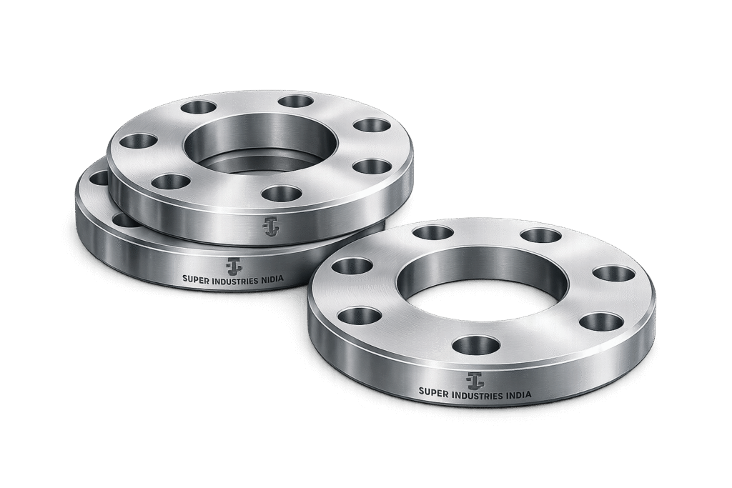
Plate Flanges are widely utilized in low to medium pressure piping systems where cost efficiency, fabrication flexibility, and dimensional adaptability are prioritized over high-pressure structural performance. Within EPC project environments, these flanges serve as a practical solution for utility-grade piping, non-critical process lines, and infrastructure networks.
From a system design standpoint, Plate Flanges are primarily applied where:
- Internal pressures remain within moderate limits
- Temperature cycles are not severe
- Structural fatigue is minimal
- Ease of fabrication and replacement is required
Functional Role in Piping Systems
Plate Flanges provide a detachable, bolted connection interface between:
- Pipe-to-pipe joints
- Pipe-to-valve connections
- Pipe-to-equipment nozzles
Unlike forged flanges, which are integrally shaped for strength, Plate Flanges are cut and machined from flat plate material, making them more suitable for applications where:
- Structural loading is predictable and moderate
- System criticality is low to intermediate
- Fabrication cost optimization is required
Typical Applications
Plate Flanges are extensively used across the following sectors:
Water & Wastewater Systems
- Pump discharge lines
- Treatment plant distribution systems
- Clarifier and filtration piping
HVAC & Utility Systems
- Chilled water pipelines
- Cooling tower connections
- Air handling unit piping
Firefighting Systems
- Sprinkler system mains
- Hydrant pipelines
- Firewater distribution networks
Low-Pressure Oil & Gas Lines
- Utility service lines
- Drain and vent systems
- Non-critical hydrocarbon transfer
Chemical & Process Plants
- Low-pressure chemical transfer lines
- Utility headers (steam condensate, cooling water)
Infrastructure & Civil Projects
- Municipal pipelines
- Irrigation systems
- Industrial utility corridors
Why Plate Flanges Are Used Instead of Forged Flanges
From an EPC procurement and engineering evaluation perspective, the selection of Plate Flanges over forged flanges is driven by several technical and economic considerations:
a. Cost Efficiency
- Plate material is significantly less expensive than forged billets
- Lower machining complexity reduces manufacturing cost
- Ideal for bulk procurement in infrastructure projects
b. Fabrication Flexibility
- Can be manufactured in large diameters not easily achievable with forging
- Custom drilling patterns can be introduced
- Thickness can be tailored to project-specific requirements
c. Material Availability
- Plate stock is widely available across carbon steel and stainless steel grades
- Reduced lead time compared to forged components
Cost vs Pressure Trade-Off
The primary limitation of Plate Flanges lies in their structural performance under pressure and temperature.
| Parameter | Plate Flanges | Forged Flanges |
|---|---|---|
| Manufacturing Cost | Lower | Higher |
| Pressure Capability | Limited | High |
| Structural Integrity | Moderate | Superior |
| Grain Structure | Rolled | Forged (refined) |
| Fatigue Resistance | Lower | Higher |
Engineering Interpretation:
- Plate Flanges are acceptable where pressure containment is not critical
- Forged flanges are mandatory in high-pressure, high-temperature, cyclic loading environments
Fabrication Advantages
From a manufacturing engineering standpoint:
- No forging dies required
- CNC cutting enables precise profiling
- Reduced material wastage
- Scalability for large-diameter flanges (>60”)
This makes Plate Flanges particularly suitable for EPC bulk supply contracts where consistency and cost control are essential.
Super Industries
Global Manufacturer of Heavy & Custom Engineered Fasteners & Flanges
2. Technical Definition of Plate Flanges
Plate Flanges are defined as:
Flat, circular metallic components manufactured from rolled plate material, machined to incorporate a central bore and bolt holes, and used to form bolted connections in piping systems.
Structural Characteristics
Key features include:
- Flat profile (no hub)
- Uniform thickness across the cross-section
- Machined bore matching pipe OD or ID requirement
- Bolt circle drilled as per standard or custom pattern
Unlike Weld Neck Flanges:
- No tapered hub
- No stress transition geometry
- Lower resistance to bending and stress concentration
Configuration: Slip-On Compatibility
Plate Flanges are typically used in:
Slip-On Welding Configuration
- Pipe is inserted into the bore
- Fillet weld applied internally and externally
- Provides moderate strength and sealing capability
Engineering Implication:
- Reduced welding complexity
- Suitable for non-critical systems
- Lower fatigue resistance compared to butt weld joints
Facing Types
Plate Flanges are commonly supplied in:
a. Flat Face (FF)
- Entire flange face is flat
- Used with soft gaskets
- Common in:
- Cast iron systems
- Low-pressure pipelines
b. Raised Face (RF)
- Raised sealing surface around bore
- Concentrates gasket load
- Improves sealing performance
Face Finish Consideration:
- Typically serrated (phonographic or concentric)
- Enhances gasket grip and sealing integrity
Pressure Limitations
Plate Flanges are generally used in:
- ASME Class 150
- Occasionally Class 300 (with caution)
Limitations arise due to:
- Absence of forged grain structure
- Lower resistance to bending stress
- Reduced load distribution capability
Structural Comparison vs Forged Flanges
| Feature | Plate Flanges | Forged Flanges |
|---|---|---|
| Grain Flow | Random (rolled) | Directional (forged) |
| Strength | Moderate | High |
| Stress Resistance | Limited | Superior |
| Crack Propagation | Higher risk | Lower risk |
| Load Distribution | Uniform but weaker | Optimized |
Super Industries
Global Manufacturer of Heavy & Custom Engineered Fasteners & Flanges
3. Engineering & Sealing Principle
The sealing performance of Plate Flanges is governed by bolt preload, gasket compression, and internal pressure interaction.
Bolt Preload Mechanics
When bolts are tightened:
- Tensile force is induced in bolts
- Compressive force is applied on flange faces
- Gasket is compressed between mating surfaces
Preload Objective:
- Achieve sufficient gasket stress to prevent leakage
Gasket Compression Behavior
Gasket performance depends on:
- Material type (soft vs metallic)
- Surface finish
- Applied compressive load
Key Principle:
Sealing occurs when gasket stress exceeds internal fluid pressure.
Sealing Stress vs Internal Pressure
- Internal pressure tends to separate flange faces
- Bolt preload must counteract this force
Failure Condition:
Leakage occurs when:
- Bolt load < pressure-induced separating force
- Gasket stress falls below sealing threshold
Load Distribution Across Plate Flanges
Due to the absence of a hub:
- Load distribution is less efficient
- Bending stresses are higher
- Flange rotation may occur under load
Engineering Limitation:
- Plate Flanges are more prone to:
- Flange face distortion
- Uneven gasket compression
Gasket Seating Stress
Initial tightening must achieve:
- Minimum seating stress (y-value)
- Ensures gasket conforms to surface irregularities
Then during operation:
- Maintain operating gasket stress (m-factor)
Face Finish Impact
Surface roughness affects:
- Gasket grip
- Micro-leakage paths
- Long-term sealing reliability
Typical finish:
- 3.2 – 6.3 µm Ra (serrated finish)
Leakage Prevention Theory
Leakage prevention depends on balancing:
- Bolt preload
- Gasket compression
- Internal pressure forces
Plate Flanges have limitations because:
- Lower rigidity leads to flange rotation
- Reduced ability to maintain uniform gasket stress
Engineering Limitation in High-Pressure Sealing
Plate Flanges are not suitable for:
- High-pressure hydrocarbon systems
- High-temperature cyclic service
- Critical containment applications
Reasons include:
- Lack of structural reinforcement
- Increased susceptibility to deformation
- Reduced fatigue resistance
4. Pressure & Load Engineering
Pressure Capability Overview
Plate Flanges are typically used in:
- Low to moderate pressure systems
- Systems where design pressure is predictable and stable
Internal Pressure vs Bolt Load
Internal pressure generates:
- Axial separating force
- Radial stress on flange
Bolt load must:
- Maintain compression
- Prevent separation
Thermal Expansion Considerations
Thermal effects introduce:
- Differential expansion between pipe and flange
- Bolt relaxation
- Gasket stress reduction
Plate Flanges are less suitable because:
- Lower stiffness amplifies deformation
Structural Rigidity Limitations
Compared to forged flanges:
- Plate Flanges exhibit higher deflection
- Increased risk of leakage under load variation
Suitability Boundary
Plate Flanges are acceptable when:
- Pressure < moderate range
- Temperature < moderate range
- System criticality is low
They are not recommended for:
- High-pressure steam lines
- Offshore hydrocarbon systems
- High-temperature process units
Dimensional & Design Logic
Key Dimensions
Plate Flanges are defined by:
- Outside Diameter (OD)
- Thickness (t)
- Bore Diameter (ID)
- Bolt Circle Diameter (BCD)
- Number of Bolt Holes
- Bolt Hole Diameter
- Facing Type (RF/FF)
ASME B16.5-Dimensional Compatibility
Although not forged, Plate Flanges are often:
- Machined to match ASME B16.5 drilling patterns
- Compatible with standard mating flanges
Important Distinction:
- Dimensional compatibility ≠ full compliance
Thickness vs Pressure Relationship
Thickness is selected based on:
- Internal pressure
- Bolt load requirements
- Flange rigidity
General principle:
Higher pressure → increased thickness required to resist bending.
Bore Diameter Logic
Bore is machined to:
- Match pipe OD (slip-on)
- Ensure proper fit and weldability
Bolt Circle Design
Bolt circle determines:
- Load distribution
- Clamping force uniformity
Incorrect BCD leads to:
- Uneven gasket compression
- Leakage risk
Design Limitation Summary
- No hub → higher stress concentration
- Flat geometry → reduced stiffness
- Plate origin → lower mechanical strength
5. Applicable Standards (ASTM / DIN / ISO / ASME)
Plate Flanges operate within a framework of dimensional compatibility standards and material specifications, rather than full forging-based compliance standards. For EPC evaluation, it is critical to distinguish between geometry conformity and material/process qualification.
ASME B16.5 — Dimensional Compatibility
ASME B16.5 defines:
- Flange outside diameters
- Bolt circle diameters (BCD)
- Bolt hole sizes and quantity
- Facing types (RF, FF)
- Pressure class envelope (Class 150, 300, etc.)
Engineering Interpretation:
Plate Flanges are often machined to match ASME B16.5 drilling and facing dimensions, ensuring interchangeability with:
- Forged slip-on flanges
- Weld neck flanges
- Blind flanges
However:
Plate Flanges are not inherently ASME B16.5 compliant unless manufactured from approved materials and validated through applicable design rules.
DIN EN 1092-1 — Plate Flange Standardization
DIN EN 1092-1 provides:
- Standardized plate flange types (Type 01, Type 05)
- PN pressure ratings (PN6, PN10, PN16, PN25, etc.)
- European drilling standards
Relevance:
- Widely used in water, HVAC, and infrastructure projects
- Preferred in EU-based EPC contracts
ISO Standards
Relevant ISO frameworks include:
- ISO 7005 (Metallic flanges)
- ISO 15649 (Piping systems fabrication)
These standards define:
- General flange geometry
- System-level requirements
ASTM Material Standards
Material compliance for Plate Flanges is governed by ASTM specifications:
Carbon Steel
- ASTM A36 (structural plate)
- ASTM A105 (only if plate meets equivalent requirements and is normalized)
Stainless Steel
- ASTM A240 (plate material for 304, 316 grades)
Alloy & Duplex Steels
- ASTM A387 (alloy plate)
- ASTM A240 (duplex grades when available in plate form)
Forged vs Plate Compliance Distinction
| Parameter | Forged Flanges | Plate Flanges |
|---|---|---|
| Governing Standard | ASME B16.5 + ASTM A105 | Dimensional + ASTM Plate Standards |
| Grain Structure | Forged | Rolled |
| Certification | Fully standardized | Conditional |
| Design Validation | Codified | Engineering judgement required |
Certification Limitations
Plate Flanges may face limitations in:
- High-pressure code acceptance
- Critical service approvals
- Nuclear or offshore compliance
Typical certification includes:
- EN 10204 3.1 Material Test Certificate (MTC)
- Dimensional inspection reports
- Optional third-party inspection
6. Material & Grade Options
Material selection directly impacts:
- Pressure capability
- Temperature resistance
- Corrosion performance
- Weldability
Carbon Steel Plate Flanges
ASTM A36
- Most widely used plate grade
- Good weldability
- Moderate strength
ASTM A105 (Plate Equivalent Condition)
- Used when plate is normalized and meets forging-equivalent properties
- Higher strength than A36
Applications:
- Water systems
- Utility pipelines
- Low-pressure oil & gas
Stainless Steel Plate Flanges
ASTM A240 Type 304
- General corrosion resistance
- Suitable for atmospheric and mild chemical exposure
ASTM A240 Type 316
- Enhanced resistance to chlorides
- Suitable for marine and chemical environments
Alloy Steel Plate Flanges
Used in limited scenarios where:
- Elevated temperature resistance required
- Moderate pressure conditions exist
Common grades:
- ASTM A387 (Cr-Mo steels)
Duplex & Super Duplex Plate Flanges
Where plate availability permits:
- Duplex (e.g., UNS S31803)
- Super Duplex (e.g., UNS S32750)
Advantages:
- High strength
- Excellent corrosion resistance
Limitation:
- Availability and cost
Material Comparison Table
| Grade | Yield Strength (MPa) | Tensile Strength (MPa) | Temperature Range | Corrosion Resistance | Typical Industry Use |
|---|---|---|---|---|---|
| ASTM A36 | ~250 | 400–550 | -29°C to 400°C | Low | Water, infrastructure |
| ASTM A105 (Normalized) | ~250–300 | 485–620 | -29°C to 425°C | Low | Oil & gas utilities |
| ASTM A240 304 | ~205 | 515–750 | -196°C to 870°C | Moderate | Food, water, HVAC |
| ASTM A240 316 | ~205 | 515–750 | -196°C to 870°C | High | Chemical, marine |
| Duplex S31803 | ~450 | 620–880 | -50°C to 300°C | Very High | Offshore, chemical |
| Super Duplex S32750 | ~550 | 750–950 | -50°C to 300°C | ممتاز | Aggressive environments |
Engineering Interpretation
- Carbon steel plate flanges are cost-effective but corrosion-prone
- Stainless steel provides corrosion resistance but lower yield strength compared to duplex
- Duplex offers strength + corrosion resistance, but fabrication control is critical
7. Heat Treatment Information
Heat treatment of plate materials significantly influences:
- Mechanical properties
- Residual stress levels
- Grain structure
Plate Rolling Condition
Plate material is typically supplied as:
- Hot rolled
- Controlled rolled
Characteristics:
- Non-directional grain structure
- Residual stresses from rolling
Normalizing (Carbon Steel)
Process:
- Heating above transformation temperature
- Air cooling
Effects:
- Refines grain structure
- Improves toughness
- Enhances uniformity
Stress Relieving
Applied after machining or welding:
- Reduces residual stresses
- Minimizes distortion during service
Solution Annealing (Stainless Steel)
Process:
- Heating to high temperature
- Rapid quenching
Effects:
- Restores corrosion resistance
- Dissolves carbides
- Improves ductility
Grain Structure Comparison
| Feature | Plate Material | Forged Material |
|---|---|---|
| Grain Orientation | Random | Directional |
| Defect Closure | Limited | Enhanced |
| Mechanical Uniformity | Moderate | High |
Mechanical Property Impact
Heat treatment improves:
- Yield strength consistency
- Toughness
- Crack resistance
However:
Plate materials do not achieve the same structural refinement as forged components.
8. Manufacturing Process of Plate Flanges
Manufacturing is based on subtractive machining from rolled plate, requiring strict dimensional control.
Plate Procurement & Inspection
- Raw material sourced as per ASTM standards
- Verification of:
- Chemical composition
- Mechanical properties
- Plate thickness tolerance
CNC / Profile Cutting
- Plasma, laser, or waterjet cutting
- Circular blank preparation
Objective:
- Achieve near-net shape with minimal distortion
Machining of Bore
- Precision boring operation
- Ensures correct fit for slip-on configuration
Tolerance control is critical for:
- Weld quality
- Alignment
Facing Machining (RF / FF)
- Lathe machining to achieve:
- Flat Face (FF)
- Raised Face (RF)
Surface finish:
- Serrated for gasket seating
Drilling of Bolt Holes
- CNC drilling for positional accuracy
- Bolt holes aligned with BCD requirements
Edge Finishing
- Deburring
- Chamfering
Prevents:
- Handling damage
- Stress concentration
Surface Preparation
- Cleaning
- Shot blasting (if required)
Final Inspection
- Dimensional verification
- Surface finish check
- Visual inspection
Marking & Traceability
Each Plate Flange is marked with:
- Material grade
- Size (NPS)
- Pressure class
- Heat number
- Manufacturer identification
9. Surface Finish Options
Surface treatment is essential for:
- Corrosion protection
- Storage stability
- Service life
Anti-Rust Oil Coating
- Temporary protection
- Used for carbon steel flanges
Black Coating
- Basic corrosion resistance
- Suitable for indoor storage
Hot-Dip Galvanizing
- Zinc coating for corrosion protection
- Suitable for:
- Water systems
- Outdoor pipelines
Epoxy Coating
- Chemical-resistant barrier
- Used in aggressive environments
Passivation (Stainless Steel)
- Chemical treatment
- Enhances corrosion resistance
- Removes surface contaminants
Surface Finish & Gasket Seating
Critical factors:
- Surface roughness must match gasket type
- Excessively smooth surface → leakage risk
- Excessively rough surface → gasket damage
Engineering Consideration
Surface finish must be selected based on:
- Fluid type
- Environmental exposure
- Storage duration
- Installation timeline
10. Inspection & Quality Control Methods
Plate Flanges, being manufactured from rolled plate material, require enhanced inspection discipline to ensure dimensional accuracy, material integrity, and suitability for EPC applications.
Positive Material Identification (PMI)
- Verifies chemical composition of material
- Confirms compliance with specified ASTM grade
- Typically performed using:
- XRF analyzers
- Optical emission spectroscopy (OES)
Application:
- Mandatory for alloy and stainless steel flanges
- Recommended for EPC-critical supply chains
Dimensional Inspection
Critical parameters inspected:
- Outside Diameter (OD)
- Bore Diameter (ID)
- Thickness
- Bolt Circle Diameter (BCD)
- Bolt hole diameter and spacing
- Facing height (RF)
Tolerance Reference:
- Based on ASME B16.5 or project-specific drawings
Ultrasonic Testing (UT)
Applicable when:
- Plate thickness is significant
- Internal defects are a concern
Detects:
- Laminations
- Internal voids
- Inclusion defects
Dye Penetrant Inspection (DPI)
Used for:
- Surface crack detection
- Machined surface inspection
Particularly relevant for:
- Stainless steel flanges
- Critical sealing surfaces
Visual Inspection
Baseline inspection for:
- Surface defects
- Machining quality
- Coating uniformity
- Marking accuracy
Documentation & Certification
Typical deliverables include:
- EN 10204 3.1 Material Test Certificate
- Dimensional inspection report
- Heat number traceability
- Coating certification (if applicable)
Third-Party Inspection
EPC projects may require inspection by:
- Independent agencies
- Client-appointed inspectors
Scope includes:
- Witnessing dimensional checks
- Reviewing MTCs
- Verifying marking and traceability
A. Technical Dimension Tables (ASME B16.5 Compatibility)
Indicative dimensions for Plate Flanges (Class 150, Raised Face)
| NPS | OD (mm) | Thickness (mm) | BCD (mm) | Bolt Size | No. of Bolts |
|---|---|---|---|---|---|
| 1/2″ | 89 | 11 | 60 | M12 | 4 |
| 1″ | 108 | 13 | 79 | M12 | 4 |
| 2″ | 152 | 16 | 120 | M16 | 4 |
| 4″ | 229 | 19 | 190 | M16 | 8 |
| 6″ | 279 | 21 | 241 | M20 | 8 |
| 8″ | 343 | 24 | 298 | M20 | 8 |
| 10″ | 406 | 26 | 362 | M24 | 12 |
| 12″ | 483 | 28 | 432 | M24 | 12 |
Engineering Note:
- Values are indicative; final dimensions must align with project specification
- Thickness may be increased for Plate Flanges to compensate for reduced rigidity
B. Pressure Rating Table (Indicative)
| ASME Class | Pressure @ 38°C (bar) | Pressure @ 200°C (bar) | Typical Use |
|---|---|---|---|
| Class 150 | ~19.6 | ~15 | Water, HVAC |
| Class 300 | ~51 | ~40 | Limited process use |
Important:
- Plate Flanges are typically restricted to Class 150 applications
- Use in Class 300 requires engineering validation
C. Torque Chart
Indicative bolt tightening torque values (carbon steel bolts, standard lubrication conditions)
| Bolt Size | Torque (Nm) – Lubricated | Torque (Nm) – Dry |
|---|---|---|
| M12 | 70 | 95 |
| M16 | 170 | 230 |
| M20 | 330 | 450 |
| M24 | 570 | 770 |
| M27 | 830 | 1100 |
| M30 | 1150 | 1500 |
Torque Application Notes
- Lubrication reduces friction → lower torque required
- Dry tightening increases variability in preload
- Torque must be applied in cross-pattern sequence
D. Preload Calculation Guide
Bolt preload is critical to achieving leak-tight flange joints.
Bolt Stress Formula
\[
\sigma = \frac{F}{A}
\]
Where:
- ( \sigma ) = Bolt stress
- ( F ) = Bolt preload force
- ( A ) = Tensile stress area
Preload Force Formula
\[
F = \frac{T \times K}{d}
\]
Where:
- ( F ) = Preload force
- ( T ) = Applied torque
- ( K ) = Torque coefficient (≈ 0.18–0.25)
- ( d ) = Nominal bolt diameter
Gasket Seating Stress
\[
S_g = \frac{F}{A_g}
\]
Where:
- ( S_g ) = Gasket stress
- ( A_g ) = Effective gasket area
Sample Calculation
Given:
- Bolt size: M20
- Torque: 330 Nm (lubricated)
- Torque factor (K): 0.2
- Diameter: 20 mm
Step 1: Calculate Preload
\[
F = \frac{330 \times 0.2}{0.02} = 3300 \, \text{N}
\]
Step 2: Check Bolt Stress
\[
\sigma = \frac{3300}{A}
\]
(Where A depends on bolt thread area)
Engineering Interpretation
- Higher preload → better sealing (up to material limits)
- Excess preload → bolt yielding or gasket crushing
- Insufficient preload → leakage
E. Yield Strength Chart (Text-Based Explanation)
Yield strength defines the maximum stress before permanent deformation.
Typical hierarchy:
- Carbon Steel (A36): ~250 MPa
- Carbon Steel (A105): ~250–300 MPa
- Stainless Steel (304/316): ~205 MPa
- Duplex Steel: ~450 MPa
- Super Duplex: ~550 MPa
Implication for Plate Flanges:
- Lower yield strength → higher deformation risk
- Plate Flanges rely heavily on thickness for rigidity
F. Mechanical Property Table
| Material | Yield Strength (MPa) | Tensile Strength (MPa) | Elongation (%) | Hardness (HB) |
|---|---|---|---|---|
| A36 | 250 | 400–550 | ~20 | ~120 |
| A105 | 250–300 | 485–620 | ~22 | ~140 |
| SS 304 | 205 | 515–750 | ~40 | ~150 |
| SS 316 | 205 | 515–750 | ~40 | ~150 |
| Duplex | 450 | 620–880 | ~25 | ~250 |
G. Corrosion Resistance Table
| Environment | Carbon Steel | SS 304 | SS 316 | Duplex |
|---|---|---|---|---|
| Atmospheric | Low | Good | Excellent | Excellent |
| Marine | Poor | Moderate | Good | Excellent |
| Chemical | Poor | Moderate | Good | Excellent |
| Water Systems | Moderate (coated) | Good | Excellent | Excellent |
11. Additional Engineering Considerations
Flange Alignment
Improper alignment leads to:
- Uneven gasket compression
- Localized stress
- Leakage
Bolt Tightening Sequence
Standard method:
- Finger tightening
- 30% torque
- 60% torque
- 100% torque
- Final circular pass
Gasket Selection
Depends on:
- Pressure
- Temperature
- Fluid type
Common types:
- Non-asbestos sheet
- Spiral wound gasket
- Rubber gasket (low pressure)
Storage & Handling
- Store in dry conditions
- Protect facing surfaces
- Avoid stacking damage
Installation Controls
- Verify flange face cleanliness
- Check bolt lubrication
- Ensure uniform torque application
Industries Served
Plate Flanges are deployed across a wide range of industries where pressure containment requirements are moderate and cost-efficiency with dimensional adaptability is required. Their application is driven by system design conditions rather than universal suitability.
Water & Wastewater Infrastructure
Plate Flanges are extensively used in:
- Raw water intake systems
- Treated water distribution lines
- Effluent discharge pipelines
- Pumping stations
Engineering Rationale:
- Low to moderate pressure range
- Corrosion can be managed via coatings or stainless steel
- Large diameter pipelines favor plate-based fabrication
HVAC & Building Services
Typical usage includes:
- Chilled water systems
- Cooling water lines
- Air handling unit piping
- District cooling networks
Key Factors:
- Stable pressure conditions
- Low cyclic loading
- Ease of installation and maintenance
Fire Protection Systems
Applications:
- Firewater mains
- Sprinkler system pipelines
- Hydrant networks
Engineering Consideration:
- Systems operate under standby conditions
- Pressure is moderate and intermittent
- Plate Flanges provide adequate sealing when properly torqued
Infrastructure & Municipal Projects
Includes:
- Irrigation systems
- Sewerage pipelines
- Urban utility corridors
Advantages:
- Cost efficiency for large-scale deployment
- Flexibility in custom drilling patterns
- Availability in large diameters
Low-Pressure Oil & Gas Applications
Used in:
- Utility pipelines
- Drain and vent systems
- Non-critical hydrocarbon services
Limitations:
- Not used in high-pressure production systems
- Not suitable for critical containment zones
Chemical & Process Plants (Utility Services)
Applicable in:
- Cooling water circuits
- Chemical transfer at low pressure
- Auxiliary process lines
Material Selection Importance:
- Stainless steel or duplex may be required
- Corrosion resistance becomes primary selection factor
12. Export Capability & Global Supply
Super Industries operates as a manufacturer and exporter of Plate Flanges, supplying to EPC contractors and global project sites with documentation aligned to international procurement practices.
Export Regions
Typical supply regions include:
- Middle East (GCC countries)
- Southeast Asia
- Africa
- Europe (for infrastructure and water systems)
Packaging Standards
Packaging is designed to prevent:
- Mechanical damage
- Corrosion during transit
- Facing surface contamination
Common methods:
- Wooden pallets / crates
- Moisture-resistant wrapping
- Plastic end protection for sealing faces
Documentation Package
Standard export documentation includes:
- Commercial Invoice
- Packing List
- EN 10204 3.1 MTC
- Dimensional Inspection Report
- Coating Certificate (if applicable)
- Third-party inspection report (if specified)
Logistics & Handling
- Bulk shipment capability for large EPC orders
- Containerized loading for export
- Marking aligned with project identification systems
Traceability
Each Plate Flange is traceable through:
- Heat number
- Material grade marking
- Inspection records
Traceability ensures:
- Compliance verification
- Audit readiness
- Field-level identification
13. Procurement & Installation View
This section reflects the practical evaluation and field-level considerations used by EPC contractors and piping engineers.
Procurement Considerations
When evaluating Plate Flanges, procurement teams assess:
a. Material Compliance
- ASTM plate certification
- Mechanical property verification
b. Dimensional Accuracy
- ASME B16.5 compatibility
- Tolerance adherence
c. Application Suitability
- Pressure rating vs system design
- Temperature limits
d. Inspection Requirements
- Availability of PMI, UT, DPI
- Third-party inspection readiness
Gasket Selection Criteria
Gasket selection must align with:
- Flange facing type (FF/RF)
- Pressure and temperature conditions
- Fluid characteristics
Examples:
- Rubber gaskets → water systems
- Spiral wound → moderate pressure
- Non-asbestos sheet → general utility
Bolt Tightening Procedure
Correct tightening is critical for sealing performance.
Recommended sequence:
- Initial hand tightening
- Cross-pattern tightening at ~30% torque
- Repeat at ~60% torque
- Final tightening at 100% torque
- Circular pass for uniform load distribution
Torque Control
- Use calibrated torque wrench
- Apply lubrication where specified
- Maintain uniform preload across all bolts
Installation Checks
Before commissioning:
- Verify flange face cleanliness
- Ensure gasket alignment
- Confirm bolt material and grade
- Check for uniform gap closure
Storage & Handling Guidelines
To maintain integrity:
- Store in dry, covered environment
- Protect RF/FF surfaces with caps or coatings
- Avoid direct ground contact
- Prevent stacking damage
14. Custom Engineering Capabilities
Plate Flanges offer flexibility in fabrication, enabling customization based on project-specific requirements.
Custom Thickness
- Increased thickness for enhanced rigidity
- Adjusted based on pressure and bolt load
Non-Standard Drilling
- Custom bolt patterns
- Special BCD configurations
- Adaptation to legacy systems
Large Diameter Plate Flanges
- Suitable for diameters beyond forging limits
- Common in water transmission pipelines
Special Coatings
- Fusion bonded epoxy (FBE)
- Heavy-duty anti-corrosion coatings
- Marine-grade protection systems
Material Customization
- Duplex and super duplex (subject to plate availability)
- Alloy steels for elevated temperature
Engineering Conclusion
Plate Flanges serve a specific and well-defined role within piping systems. Their applicability is governed by pressure limitations, structural characteristics, and material properties.
Technical Suitability Summary
Plate Flanges are suitable for:
- Low to moderate pressure systems
- Utility and infrastructure applications
- Large-diameter piping
- Cost-sensitive EPC projects
Engineering Limitations
They are not suitable for:
- High-pressure systems
- High-temperature cyclic service
- Critical hydrocarbon containment
- Applications requiring high fatigue resistance
Structural Understanding
From an engineering standpoint:
- Lack of forged grain structure reduces strength
- Flat geometry limits rigidity
- Sealing depends heavily on bolt preload and gasket behavior
EPC Evaluation Perspective
For EPC contractors and consultants:
Plate Flanges are acceptable when design conditions fall within defined limits and when dimensional compatibility, material traceability, and inspection compliance are verified.
Final Technical Position
This document establishes that:
- Plate Flanges are dimensionally adaptable, fabrication-efficient components
- Their use requires clear understanding of mechanical limitations
- Proper design, material selection, and installation practices are essential for performance