
ASME B16.36 Orifice Flanges
Super Industries
“Global Manufacturer of Heavy & Custom Engineered Fasteners for Oil & Gas, Power & EPC Contractors.”
1. Industry Context & System Relevance
Role in Industrial Piping Systems
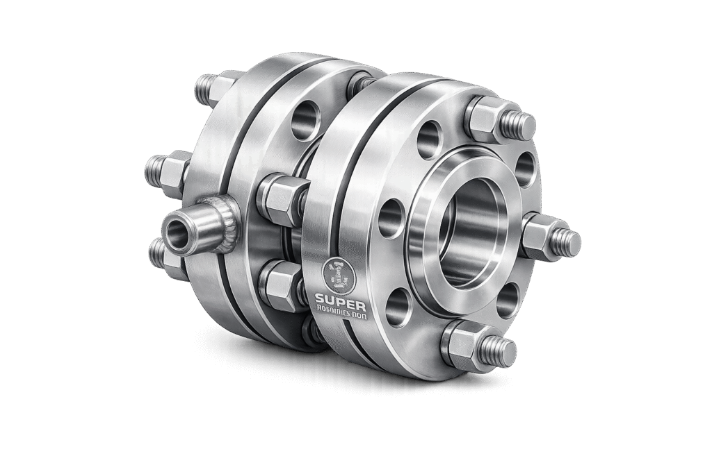
ASME B16.36 Orifice Flanges are specialized piping components designed to facilitate accurate flow measurement using the differential pressure (DP) principle. Unlike standard flanges, these are engineered specifically to integrate with orifice plate assemblies, forming a complete flow measurement flange system.
Their function is not merely mechanical joining — they act as measurement interfaces within pressurized pipelines.
Functional Purpose in Flow Measurement
In industrial process systems, particularly in hydrocarbons and utilities, flow measurement must be:
- Repeatable
- Calibratable
- Standardized
- Compatible with instrumentation
Orifice flanges provide this by enabling:
- Installation of an orifice plate inside the pipeline
- Measurement of pressure differential across the restriction
- Transmission of pressure signals to DP transmitters
System Integration Architecture
A typical orifice flange installation includes:
- Upstream flange with pressure tap
- Downstream flange with pressure tap
- Orifice plate sandwiched between flanges
- Gaskets ensuring pressure-tight sealing
- Impulse lines connected to pressure transmitters
This assembly forms a primary flow measurement element in accordance with flow measurement standards.
Applications Across Industries
Orifice flange systems are deployed in:
Oil & Gas Pipelines
- Custody transfer metering
- Gas flow measurement
- Crude oil transport monitoring
Refineries
- Process stream monitoring
- Fuel gas measurement
- Distillation unit flow control
Petrochemical Plants
- Chemical dosing control
- Reactor feed monitoring
Power Plants
- Steam flow measurement
- Boiler feedwater monitoring
LNG Terminals
- Cryogenic fluid measurement
- Vapor flow tracking
Offshore Platforms
- Compact metering solutions
- High-pressure flow systems
General Process Industries
- Water systems
- Utility distribution networks
Why Orifice Flanges Instead of Standard Flanges
Standard flanges lack the following essential features:
| Requirement | Standard Flanges | Orifice Flanges |
|---|---|---|
| Pressure tapping | Not available | Integrated |
| Orifice plate support | Not designed | Designed specifically |
| Measurement capability | None | Full DP measurement |
| Maintenance access | Limited | Jack screws provided |
| Instrumentation integration | External modification required | Built-in |
Thus, ASME B16.36 Orifice Flanges eliminate the need for external drilling, ensuring:
- Dimensional accuracy
- Repeatable measurement geometry
- Reduced installation errors
Importance in Measurement Accuracy
Flow accuracy depends heavily on:
- Precise positioning of pressure taps
- Smooth bore alignment
- Consistent restriction geometry
Orifice flanges ensure:
- Factory-controlled tap location
- Concentric alignment with pipe bore
- Compliance with flow measurement standards
This directly impacts:
- Measurement uncertainty
- Calibration reliability
- Regulatory compliance
Maintenance & Operational Advantages
Orifice flanges are equipped with jack screws, which serve a critical function:
- Facilitate separation of flanges
- Allow safe removal of the orifice plate
- Enable inspection and replacement without pipeline damage
This is essential in systems where:
- Periodic calibration is required
- Plate wear or erosion occurs
- Process conditions change
Super Industries
Global Manufacturer of Heavy & Custom Engineered Fasteners & Flanges
2. Technical Definition
Definition
ASME B16.36 Orifice Flanges are pressure-retaining flanges specifically designed to house orifice plates and enable differential pressure measurement, incorporating:
- Precisely machined pressure tap holes
- Integrated jack screws
- Controlled bore geometry
- Compatibility with standard flange dimensions
Core Design Characteristics
1. Pressure Tap Holes
Each flange includes:
- One or more radial pressure tapping points
- Threaded connections for impulse lines
- Accurate positioning relative to orifice plate
These taps are used to measure:
- Upstream pressure
- Downstream pressure
2. Tap Configurations
Common configurations include:
Flange Taps
- Located 1 inch from flange face (standard)
- Most widely used configuration
Corner Taps
- Located at plate faces
- Used in specific measurement standards
Custom Tap Configurations
- Based on ISO or project specifications
3. Jack Screws
Integrated threaded holes enable:
- Controlled flange separation
- Safe removal of orifice plate
- Prevention of flange damage
4. Bore Alignment
Critical requirement:
- Bore must align perfectly with pipe ID
- Concentricity tolerance must be tightly controlled
Misalignment leads to:
- Flow disturbances
- Measurement errors
5. Facing Types
Available as:
Raised Face (RF)
- General-purpose applications
- Suitable for most pressure classes
Ring Type Joint (RTJ)
- High-pressure systems
- Metal-to-metal sealing
6. Pressure Containment with Instrumentation Ports
Despite the presence of drilled taps:
- Structural integrity must be maintained
- Leak-proof sealing at tapping points is mandatory
Thread types typically include:
- NPT
- BSP (project-specific)
3. Engineering & Flow Measurement Principle
Fundamental Concept
Orifice flanges operate based on the differential pressure flow measurement principle, derived from fluid mechanics.
Working Mechanism
- Fluid flows through a pipeline
- Orifice plate introduces a restriction
- Velocity increases at restriction
- Static pressure decreases
- Pressure difference (ΔP) is generated
- ΔP is measured via flange taps
- Flow rate is calculated
Governing Physics
Continuity Equation
Mass conservation:

Where:
- (Q) = flow rate
- (A) = cross-sectional area
- (V) = velocity
Bernoulli’s Principle
Energy conservation:

This explains:
- Pressure drop due to velocity increase
- Relationship between pressure and flow
Flow Rate Equation (Orifice Flow)
The volumetric flow rate is given by:
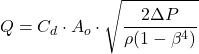
Where:
- (C_d) = discharge coefficient
- (A_o) = orifice area
- (\Delta P) = differential pressure
- (\rho) = fluid density
- (\beta) = ratio of orifice diameter to pipe diameter
Discharge Coefficient (Cd)
Accounts for:
- Non-ideal flow conditions
- Viscosity effects
- Edge sharpness
Typical range:
- 0.6 to 0.65 (depending on Reynolds number and geometry)
Flow vs Pressure Relationship
Key relationship:

Implication:
- Small measurement error in ΔP → amplified error in flow
- Requires precise tap positioning and calibration
Accuracy Considerations
Flow accuracy depends on:
- Proper installation
- Smooth upstream flow profile
- Correct plate geometry
- Accurate pressure measurement
Typical accuracy:
- ±0.5% to ±2% (depending on system design)
Limitations vs Other Flow Meters
| Parameter | Orifice Flange System | Advanced Flow Meters |
|---|---|---|
| Accuracy | Moderate | High |
| Cost | Low | High |
| Maintenance | Moderate | Low |
| Pressure loss | High | Low |
| Simplicity | High | Moderate |
Engineering Trade-Off
Orifice flange systems are preferred when:
- Standardization is required
- Cost control is critical
- Maintenance access is available
- High accuracy is not mission-critical
System Dependency on Flange Design
Measurement reliability is directly linked to:
- Tap hole precision
- Bore finish
- Plate centering
- Flange alignment
Thus, ASME B16.36 Orifice Flanges are not interchangeable with standard flanges in measurement applications.
4. Applicable Standards (ASME / ASTM / ISO / DIN)
Primary Governing Standard
ASME B16.36 — Orifice Flanges
This is the principal standard defining:
- Dimensional requirements for orifice flanges
- Pressure tap locations and configurations
- Pressure class ratings (Class 300 to 2500 typical coverage)
- Facing types (RF / RTJ)
- Bore alignment requirements
It ensures that ASME B16.36 Orifice Flanges are:
- Interchangeable across manufacturers
- Compatible with standard piping systems
- Suitable for differential pressure measurement
Related Dimensional Standard
ASME B16.5 — Pipe Flanges and Flanged Fittings
Provides:
- Bolt circle dimensions
- Flange outside diameter
- Thickness and pressure ratings
- Gasket seating details
Orifice flanges adopt these base dimensions while incorporating:
- Pressure taps
- Jack screw provisions
Flow Measurement Standards
ASME MFC-3M
Covers:
- Measurement of fluid flow in pipes using orifice plates
- Calculation methodologies
- Installation guidelines
ISO 5167
International standard governing:
- Orifice plate design
- Differential pressure measurement methods
- Flow calculation equations
- Accuracy requirements
This standard is critical for:
- Custody transfer systems
- International project compliance
Material Standards (ASTM)
Material selection for orifice flanges is governed by:
- ASTM A105 – Carbon steel forgings
- ASTM A350 LF2 – Low-temperature carbon steel
- ASTM A182 – Stainless and alloy steel forgings
These standards define:
- Chemical composition
- Mechanical properties
- Heat treatment conditions
- Testing requirements
Standards Mapping to Functional Requirements
| Requirement | Governing Standard |
|---|---|
| Dimensional accuracy | ASME B16.36 |
| Pressure rating | ASME B16.5 |
| Flow calculation | ISO 5167 / ASME MFC-3M |
| Material integrity | ASTM standards |
| Inspection documentation | EN 10204 |
5. Material & Grade Options
Material selection directly affects:
- Corrosion resistance
- Pressure-temperature capability
- Mechanical strength
- Service life
Carbon Steel Grades
ASTM A105
- Most widely used forging material
- Suitable for ambient and moderate temperature service
- Good machinability
- Cost-effective for general applications
ASTM A350 LF2
- Designed for low-temperature applications
- Improved impact toughness
- Used in LNG and cryogenic systems
Stainless Steel Grades
ASTM A182 F304
- General corrosion resistance
- Suitable for water, steam, and mild chemicals
ASTM A182 F316
- Enhanced corrosion resistance due to molybdenum
- Suitable for chlorides and aggressive chemicals
- Preferred in offshore and marine environments
Alloy Steel Grades
ASTM A182 F11 / F22
- High-temperature service
- Improved creep resistance
- Used in power plants and refineries
Duplex & Super Duplex Stainless Steels
- High strength + corrosion resistance
- Resistant to stress corrosion cracking
- Used in offshore, subsea, and aggressive chemical environments
Material Comparison Table
| Grade | Yield Strength (MPa) | Tensile Strength (MPa) | Temperature Range | Corrosion Resistance | Typical Application |
|---|---|---|---|---|---|
| A105 | ~250 | 485–620 | -29°C to 425°C | Moderate | Oil & gas pipelines |
| A350 LF2 | ~250 | 485–620 | -46°C and below | Moderate | LNG, low-temp service |
| F304 | ~205 | 515 | Up to 870°C | Good | Water, chemicals |
| F316 | ~205 | 515 | Up to 870°C | Excellent | Marine, chemical |
| F11 | ~275 | 415–585 | Up to 540°C | Moderate | Power plants |
| F22 | ~415 | 585–760 | Up to 600°C | Moderate | High-temp service |
| Duplex | ~450 | 620–880 | -50°C to 300°C | Very high | Offshore |
| Super Duplex | ~550 | 750–950 | -50°C to 300°C | ممتاز | Subsea, corrosive |
6. Heat Treatment Information
Heat treatment is essential for:
- Mechanical property enhancement
- Residual stress relief
- Dimensional stability during machining
1. Normalizing
- Refines grain structure
- Improves uniformity
- Enhances strength
Used for:
- Carbon steel flanges
2. Quenching & Tempering
- Increases strength and hardness
- Improves toughness
Used for:
- Alloy steels (F11, F22)
3. Stress Relieving
- Reduces residual stresses after machining
- Prevents distortion during service
Critical for:
- Flanges with pressure taps (stress concentration zones)
4. Solution Annealing
- Dissolves carbides
- Restores corrosion resistance
Used for:
- Stainless steels
- Duplex grades
Impact of Heat Treatment
| Property | Effect |
|---|---|
| Machinability | Improved |
| Dimensional stability | Enhanced |
| Crack resistance | Increased |
| Fatigue performance | Improved |
7. Manufacturing Process
Manufacturing of ASME B16.36 Orifice Flanges requires high precision due to:
- Flow measurement sensitivity
- Tap alignment criticality
Step-by-Step Process
1. Raw Material Inspection
- Chemical analysis (spectrometry)
- Verification against ASTM standards
- Traceability marking
2. Forging
- Open-die or closed-die forging
- Grain flow aligned with stress direction
- Eliminates internal defects
3. Heat Treatment
- As per material grade
- Ensures required mechanical properties
4. Rough Machining
- OD turning
- Bore preparation
- Face leveling
5. CNC Machining
Critical stage involving:
- Precision bore machining
- Facing (RF / RTJ)
- Bolt hole drilling
Tolerance control is essential.
6. Bore Finishing
- Surface smoothness critical for flow
- Prevents turbulence and measurement error
7. Pressure Tap Hole Drilling (CRITICAL OPERATION)
This is the defining feature of orifice flanges:
- Radial drilling at exact specified distance
- Threading (NPT or BSP)
- Alignment verification
Tolerance errors can lead to:
- Incorrect ΔP measurement
- Flow inaccuracies
8. Jack Screw Threading
- Precision tapping for jack screws
- Ensures safe plate removal
9. Facing Machining
RF:
- Serrated finish for gasket seating
RTJ:
- Groove machining with tight tolerances
10. Final Inspection
- Dimensional checks
- Tap alignment verification
- Surface finish inspection
11. Marking & Traceability
Includes:
- Heat number
- Material grade
- Size and pressure class
- Manufacturer identification
8. Surface Finish Options
Surface finishing is selected based on:
- Corrosion environment
- Storage duration
- Project specifications
Common Surface Treatments
Anti-Rust Oil
- Temporary protection
- Used for short-term storage
Black Coating
- Oxide layer formation
- Moderate corrosion resistance
Zinc Plating
- Electroplated coating
- Improved corrosion resistance
- Suitable for mild environments
Hot-Dip Galvanizing
- Thick zinc coating
- Long-term outdoor protection
Passivation
- Removes free iron
- Enhances corrosion resistance of stainless steel
Surface Roughness & Gasket Compatibility
| Facing Type | Surface Finish Requirement |
|---|---|
| RF | 125–250 AARH serrated |
| RTJ | Smooth groove finish |
Engineering Considerations
Surface finish affects:
- Gasket sealing performance
- Leak prevention
- Long-term reliability
A. Technical Dimension Tables (Representative — ASME B16.36 with B16.5 Integration)
Note: Dimensions are aligned with ASME B16.36 Orifice Flanges in conjunction with ASME B16.5 base flange geometry. Exact values may vary based on project specification, facing type, and tapping configuration.
Class 300 Orifice Flanges (Raised Face – RF)
| NPS | OD (mm) | Thickness (mm) | Bore (mm) | Bolt Circle (mm) | Bolt Size | No. of Bolts | Tap Size | Jack Screws |
|---|---|---|---|---|---|---|---|---|
| 2″ | 165 | 25 | 52.5 | 127 | M16 | 8 | 1/2″ NPT | 2 |
| 4″ | 254 | 32 | 102.3 | 190 | M20 | 8 | 1/2″ NPT | 2 |
| 6″ | 279 | 36 | 154.1 | 241 | M22 | 12 | 1/2″ NPT | 2 |
| 8″ | 343 | 41 | 202.7 | 298 | M24 | 12 | 1/2″ NPT | 2 |
| 10″ | 406 | 48 | 254.5 | 362 | M27 | 16 | 1/2″ NPT | 2 |
| 12″ | 483 | 51 | 303.2 | 432 | M30 | 16 | 1/2″ NPT | 2 |
Class 600 Orifice Flanges (Raised Face – RF)
| NPS | OD (mm) | Thickness (mm) | Bore (mm) | Bolt Circle (mm) | Bolt Size | No. of Bolts | Tap Size | Jack Screws |
|---|---|---|---|---|---|---|---|---|
| 2″ | 165 | 32 | 52.5 | 127 | M16 | 8 | 1/2″ NPT | 2 |
| 4″ | 273 | 38 | 102.3 | 190 | M20 | 8 | 1/2″ NPT | 2 |
| 6″ | 318 | 45 | 154.1 | 241 | M22 | 12 | 1/2″ NPT | 2 |
| 8″ | 381 | 51 | 202.7 | 298 | M24 | 12 | 1/2″ NPT | 2 |
| 10″ | 444 | 57 | 254.5 | 362 | M30 | 16 | 1/2″ NPT | 2 |
| 12″ | 521 | 64 | 303.2 | 432 | M33 | 16 | 1/2″ NPT | 2 |
Dimensional Engineering Considerations
- Bore tolerance: critical for flow profile stability
- Tap hole distance: typically 25.4 mm (1 inch) from flange face (flange taps)
- Concentricity: must align with pipe ID to prevent asymmetric flow
B. Pressure Rating Table (ASME B16.5 Reference)
Carbon Steel (A105) — Pressure vs Temperature
| Class | 38°C | 100°C | 200°C | 300°C | 400°C |
|---|---|---|---|---|---|
| 150 | 19.6 bar | 17.7 | 15.2 | 13.2 | 11.4 |
| 300 | 51.1 bar | 46.6 | 40.0 | 34.7 | 30.2 |
| 600 | 102.1 bar | 93.1 | 80.0 | 69.5 | 60.4 |
| 900 | 153.2 bar | 139.7 | 120.0 | 104.2 | 90.6 |
| 1500 | 255.3 bar | 232.8 | 200.0 | 173.7 | 151.0 |
| 2500 | 425.5 bar | 388.0 | 333.0 | 289.4 | 251.5 |
Engineering Interpretation
- Pressure rating reduces with temperature increase
- Material grade affects allowable stress
- Orifice flanges must maintain integrity despite tap-induced stress concentration
C. Torque Chart
Based on carbon steel bolts, standard lubrication conditions.
| Bolt Size | Torque (Nm) – Lubricated | Torque (Nm) – Dry |
|---|---|---|
| M16 | 120 | 160 |
| M20 | 240 | 320 |
| M22 | 320 | 420 |
| M24 | 420 | 560 |
| M27 | 620 | 820 |
| M30 | 850 | 1100 |
| M33 | 1150 | 1500 |
Torque Engineering Notes
- Lubrication reduces friction → lower torque required
- Over-tightening can distort orifice plate alignment
- Uniform tightening sequence is mandatory
D. Flow Calculation Guide
Orifice Flow Equation
Parameter Definitions
- (Q) = Volumetric flow rate
- (C_d) = Discharge coefficient
- (A_o) = Orifice area
- (\Delta P) = Differential pressure
- (\rho) = Fluid density
- (\beta) = Diameter ratio
Sample Calculation
Given:
- Pipe diameter = 100 mm
- Orifice diameter = 50 mm → β = 0.5
- ΔP = 10,000 Pa
- Density = 1000 kg/m³
- Cd = 0.62
Step 1: Orifice Area
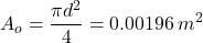
Step 2: Flow Rate



Engineering Insight
- Flow rate increases with √ΔP
- Higher β ratio reduces pressure drop but affects accuracy
- Cd must be calibrated based on Reynolds number
E. Differential Pressure vs Flow Rate Table
| ΔP (Pa) | Flow Rate (m³/s) |
|---|---|
| 2,500 | 0.0028 |
| 5,000 | 0.0040 |
| 10,000 | 0.0056 |
| 20,000 | 0.0080 |
| 40,000 | 0.0113 |
Interpretation
- Non-linear relationship
- Doubling ΔP does not double flow
- Requires calibrated instrumentation
F. Mechanical Property Table
| Material | Yield Strength (MPa) | Tensile Strength (MPa) | Hardness (HB) | Impact (J) |
|---|---|---|---|---|
| A105 | 250 | 485–620 | 120–180 | 27 |
| LF2 | 250 | 485–620 | 120–180 | 40 (low temp) |
| F304 | 205 | 515 | 150–200 | 60 |
| F316 | 205 | 515 | 150–200 | 60 |
| F22 | 415 | 585–760 | 170–220 | 30 |
| Duplex | 450 | 620–880 | 250 | 80 |
G. Corrosion Resistance Table
| Environment | Carbon Steel | SS 304 | SS 316 | Duplex | Super Duplex |
|---|---|---|---|---|---|
| Marine | Poor | Moderate | Good | Excellent | Superior |
| Acidic | Poor | Moderate | Good | Excellent | Superior |
| Hydrocarbon | Good | Excellent | Excellent | Excellent | Excellent |
| Humid | Moderate | Good | Excellent | Excellent | Superior |
9. Inspection & Quality Control Methods
Material Verification
PMI (Positive Material Identification)
- Confirms chemical composition
- Ensures correct alloy grade
Non-Destructive Testing (NDT)
Ultrasonic Testing (UT)
- Detects internal defects
- Ensures forging integrity
Magnetic Particle Inspection (MPI)
- Surface crack detection (ferromagnetic materials)
Dye Penetrant Inspection (DPI)
- Detects surface discontinuities
- Used for stainless steel
Dimensional Inspection
Critical checks:
- Bore diameter
- Flange thickness
- Bolt hole alignment
- Facing geometry
Tap Alignment Verification (CRITICAL)
- Position tolerance must meet ASME B16.36
- Angular deviation must be minimal
- Ensures accurate ΔP measurement
Pressure Tap Testing
- Leak testing at tapping points
- Thread integrity verification
- Ensures no pressure loss
Hydrostatic / Pressure Testing (if specified)
- Confirms pressure containment capability
Documentation & Certification
EN 10204 Certification
- 3.1 – Manufacturer test certificate
- 3.2 – Third-party verified certificate
Third-Party Inspection
Typically performed by:
- Independent inspection agencies
- Client-appointed inspectors
- EPC project QA/QC teams
Inspection Traceability
Each flange is traceable via:
- Heat number
- Batch number
- Inspection records
- Material certificates
10. Industries Served
ASME B16.36 Orifice Flanges are deployed in systems where repeatable, standard-compliant differential pressure flow measurement is required under varying pressure, temperature, and fluid conditions.
Oil & Gas (Upstream, Midstream, Downstream)
Functional Roles:
- Custody transfer metering (gas and liquid hydrocarbons)
- Wellhead flow monitoring
- Pipeline transmission measurement
Engineering Considerations:
- High-pressure classes (600–2500)
- Sour service compatibility (material selection critical)
- Compliance with ISO 5167 and custody transfer standards
Refineries
Applications:
- Process stream flow control
- Fuel gas measurement
- Crude distillation unit monitoring
System Requirements:
- High-temperature capability
- Resistance to corrosive hydrocarbons
- Integration with distributed control systems (DCS)
Petrochemical Plants
Applications:
- Reactor feed measurement
- Chemical dosing systems
- Utility distribution
Key Requirements:
- Chemical compatibility (SS316 / Duplex)
- Measurement stability under varying loads
Power Generation (Thermal & Nuclear Auxiliaries)
Applications:
- Steam flow measurement
- Boiler feedwater monitoring
- Condensate systems
Engineering Requirements:
- High-temperature alloy steels (F11 / F22)
- Resistance to thermal cycling
- Long-term dimensional stability
LNG & Cryogenic Systems
Applications:
- LNG transfer lines
- Vapor flow measurement
- Cryogenic storage systems
Material Requirements:
- Low-temperature toughness (A350 LF2, stainless steel)
- Impact-tested materials
Offshore & Subsea Installations
Applications:
- Platform flow monitoring
- Subsea pipeline systems
Engineering Challenges:
- Corrosion resistance (duplex / super duplex)
- Compact installation constraints
- Maintenance accessibility
Water, Utilities & Process Industries
Applications:
- Water distribution systems
- Industrial utilities
- Effluent treatment plants
Requirements:
- Cost-effective material selection
- Moderate pressure classes
- Ease of maintenance
11. Export Capability & Global Supply
Super Industries operates as a manufacturer and global exporter of ASME B16.36 Orifice Flanges, aligned with EPC project supply requirements.
Global Supply Regions
Typical export destinations include:
- Middle East (UAE, Saudi Arabia, Qatar, Kuwait)
- Southeast Asia (Singapore, Indonesia, Malaysia)
- Europe (Germany, Italy, Netherlands)
- Africa (Nigeria, Egypt)
- North America (project-specific supply)
Export Packaging Standards
Packaging is designed to ensure:
- Mechanical protection
- Corrosion prevention
- Traceability retention
Methods include:
- Wooden boxes (ISPM 15 compliant)
- Palletized loads
- Individual flange wrapping with VCI material
- End protection for facing surfaces
Documentation Package
Each shipment can be supplied with:
- Commercial invoice
- Packing list
- Material Test Certificates (EN 10204 3.1 / 3.2)
- PMI reports
- NDT reports (UT, MPI, DPI)
- Dimensional inspection reports
- Heat treatment records
- Third-party inspection release notes
Logistics & Project Handling
- Batch-wise supply for large EPC projects
- Marking aligned with project tagging systems
- Coordination with freight forwarders
- Break-bulk and container shipments
Project Supply Capability
Supports:
- EPC contractors
- Process licensors
- Engineering consultants
Capabilities include:
- Bulk production for pipeline packages
- Custom engineering for project-specific requirements
- Integration with instrumentation vendors
12. Procurement & Installation Engineering View
1. Orifice Plate Installation
Correct installation sequence:
- Verify flange orientation (tap alignment)
- Insert gasket on upstream flange
- Position orifice plate (correct flow direction marking)
- Insert downstream gasket
- Align flanges concentrically
- Install bolts and hand-tighten
2. Alignment with Pressure Taps
- Taps must be located correctly (top/bottom or side depending on service)
- Misalignment results in incorrect ΔP measurement
- Horizontal vs vertical installation must be considered
3. Gasket Selection
Depends on:
- Pressure class
- Temperature
- Fluid type
Common types:
- Spiral wound gaskets (RF)
- Ring type joint (RTJ) gaskets
4. Bolt Tightening Sequence
- Cross-pattern tightening (star sequence)
- Incremental torque application
- Final torque as per torque chart (Part 3)
Engineering objective:
- Uniform gasket compression
- Avoid flange distortion
5. Instrument Connection
- Impulse lines connected to tap holes
- Isolation valves installed
- Condensate pots (for steam service)
- Proper slope for impulse lines
6. Commissioning & Calibration
- Zero calibration of DP transmitter
- Leak testing at tap connections
- Verification against known flow conditions
7. Maintenance Using Jack Screws
Procedure:
- Depressurize system
- Loosen flange bolts
- Engage jack screws evenly
- Separate flanges gradually
- Remove orifice plate
Advantages:
- Prevents flange face damage
- Controlled separation
- Safe maintenance operation
8. Calibration & Accuracy Considerations
Accuracy depends on:
- Plate edge sharpness
- Tap cleanliness
- Instrument calibration
- Flow profile (upstream straight length)
13. Custom Engineering Capabilities
1. Non-Standard Tap Configurations
- Corner taps
- Radius taps
- Multi-tap configurations
2. High-Pressure Orifice Flanges
- Class 1500 / 2500
- Reinforced designs
- RTJ facing customization
3. Special Bore Tolerances
- Tight bore concentricity
- Custom β ratio compatibility
4. RTJ Customization
- Groove profiling
- Ring number compatibility
5. Instrument-Integrated Flange Systems
- Pre-mounted impulse connections
- Integrated manifolds (project-specific)
14. Engineering Summary & Technical Conclusion
ASME B16.36 Orifice Flanges function as precision-engineered measurement interfaces rather than conventional piping connectors.
Their performance directly influences:
- Flow measurement accuracy
- Process control stability
- Custody transfer reliability
Key Engineering Characteristics
- Integrated pressure tapping system
- Controlled bore geometry
- Compatibility with international flow standards
- Structural integrity under pressure and thermal loads
Design & Manufacturing Criticality
Reliable performance requires:
- Accurate tap positioning
- High-quality forging
- Controlled machining tolerances
- Verified inspection procedures
System-Level Importance
In a differential pressure flow system:
- Orifice plate = primary restriction element
- Orifice flange = measurement interface
- Instrumentation = data acquisition
Failure in flange design affects the entire system.
Procurement Evaluation Perspective
From an EPC and consultant standpoint, acceptable supply must demonstrate:
- Compliance with ASME B16.36 and related standards
- Documented material traceability
- Verified tap alignment and dimensional accuracy
- Complete inspection and certification records
Final Engineering Position
A properly designed and manufactured ASME B16.36 Orifice Flange system ensures:
- Repeatable and standard-compliant flow measurement
- Mechanical reliability under operating conditions
- Integration readiness with instrumentation systems