
ASME B16.5 Reducing Flanges
Global Manufacturer of Heavy & Custom Engineered Fasteners for Oil & Gas, Power & EPC Contractors.
1. Industry Context & System Relevance
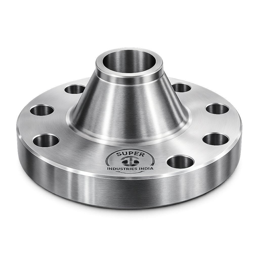
Role of ASME B16.5 Reducing Flanges in Piping Systems
In engineered piping systems, transitions between different pipe sizes are unavoidable due to:
- Flow rate adjustments
- Equipment nozzle size mismatches
- Pressure management requirements
- Layout constraints in compact installations
ASME B16.5 Reducing Flanges provide a direct, bolted transition between two different nominal pipe sizes by integrating the function of a reducer into the flange geometry itself.
Functional Role:
- Connect a larger nominal pipe size (NPS) to a smaller pipe
- Maintain a bolted joint instead of a welded transition
- Enable disassembly and maintenance access at size transition points
- Reduce system complexity in congested piping layouts
Why Use Reducing Flanges Instead of Reducer + Standard Flange
Conventional Approach:
- Pipe → Reducer (butt weld) → Pipe → Standard Flange
Reducing Flange Approach:
- Pipe → Reducing Flange (single component)
Engineering Comparison:
| Parameter | Reducer + Flange | Reducing Flange |
|---|---|---|
| Number of welds | 2 | 0 or 1 |
| Installation time | Higher | Lower |
| Alignment complexity | Moderate | Lower |
| Leak points | Higher | Reduced |
| Space requirement | Larger | Compact |
| Maintenance access | Limited | Improved |
Key Engineering Advantages:
1. Weld Reduction
- Eliminates additional butt weld joints
- Reduces welding inspection scope (RT/UT)
2. Compact System Design
- Critical in:
- Offshore modules
- Skid-mounted systems
- Pipe racks with high density
3. Maintenance Efficiency
- Bolted joint allows easy removal
- No need for cutting welded reducers
4. Cost Optimization
- Lower fabrication cost
- Reduced welding consumables and labor
Application Areas
ASME B16.5 Reducing Flanges are widely used across high-integrity industries:
Oil & Gas (Upstream / Midstream / Downstream)
- Wellhead systems
- Gathering lines
- Refinery process units
Petrochemical Plants
- Reactor inlet/outlet connections
- Pump suction and discharge lines
Power Plants
- Boiler feedwater systems
- Steam distribution lines
LNG Terminals
- Cryogenic process piping
- Regasification systems
Offshore Platforms
- Space-constrained piping networks
- Modular skid-based piping
Water & Utility Infrastructure
- Pumping stations
- Treatment plant pipelines
System Design Impact
Space Optimization
Reducing flanges eliminate the need for separate reducers, making them suitable for:
- Congested piping corridors
- Vertical pipe risers
- Skid-mounted process systems
Installation Efficiency
- Reduced field welding
- Simplified alignment
- Lower dependency on welding qualification procedures
Maintenance Considerations
- Easier disassembly
- Reduced downtime during inspection
- Simplified gasket replacement
Super Industries
Global Manufacturer of Heavy & Custom Engineered Fasteners & Flanges
2. Technical Definition
Formal Definition
ASME B16.5 Reducing Flanges are flanges in which the bore size is smaller than the nominal pipe size of the flange, enabling direct connection between pipelines of different diameters without the use of a separate reducer fitting.
Geometry Characteristics
Bore Reduction
- The flange outer dimensions correspond to the larger NPS
- The internal bore is machined to a smaller diameter
- Bore transition is typically concentric
Structural Integration
- Combines:
- Pressure-retaining flange geometry
- Flow transition geometry
Available Configurations
Weld Neck Reducing Flange
- Gradual bore transition
- Preferred for high-pressure and high-temperature service
- Better stress distribution
Slip-On Reducing Flange
- Pipe inserted into flange bore
- Used in moderate pressure applications
- Less favorable for critical services
Threaded Reducing Flange
- Used in low-pressure, non-critical systems
- Eliminates welding
Facing Types
Flat Face (FF)
- Used in low-pressure systems
- Typically for cast iron or non-metallic connections
Raised Face (RF)
- Most commonly used
- Provides controlled gasket compression
Ring Type Joint (RTJ)
- Used in high-pressure and high-temperature applications
- Metal-to-metal sealing
Concentric vs Eccentric Considerations
Concentric Reduction (Standard)
- Bore centered within flange
- Uniform stress distribution
- Standard manufacturing approach
Eccentric Reduction (Not Typical)
- Rare in flanges
- Typically achieved using eccentric reducers instead
- Used when:
- Avoiding air pockets (horizontal lines)
- Maintaining bottom or top alignment
Conclusion:
Reducing flanges are generally concentric, and eccentric transitions are handled using separate fittings.
Pressure Containment Consideration
The geometry transition introduces:
- Localized stress concentration
- Change in flow profile
- Reduced cross-sectional area
Design must ensure:
- Adequate wall thickness
- Smooth bore transition
- Compliance with ASME pressure ratings
3. Engineering & Flow Principles
Flow Behavior Through Reducing Flanges
When fluid flows from a larger pipe into a smaller bore:
- Velocity increases
- Static pressure decreases
- Flow profile changes
Continuity Principle
The continuity equation governs flow behavior:
- Flow rate remains constant
- Velocity changes inversely with cross-sectional area
Implication:
Smaller bore → Higher velocity
Bernoulli Principle Relevance
Energy balance in fluid flow:
- Increase in velocity → Decrease in pressure
- Pressure drop occurs across reduction
Engineering Impact:
- Potential cavitation (in liquids)
- Pressure loss must be accounted for
Turbulence and Flow Disturbance
Causes:
- Sudden reduction in diameter
- Improper bore transition machining
- Surface roughness
Effects:
- Increased turbulence
- Energy losses
- Noise and vibration
Erosion & Wear Risks
High-velocity flow through reduced bore can cause:
- Internal surface erosion
- Material degradation
- Reduced service life
High-Risk Fluids:
- Slurries
- Sand-laden hydrocarbons
- High-velocity steam
Impact on Downstream Equipment
Improper use of reducing flanges may affect:
- Pump suction stability
- Valve performance
- Flow meter accuracy
When Reducing Flanges Are NOT Recommended
Avoid use in:
- High turbulence-sensitive systems
- Slurry or abrasive service
- Critical flow measurement lines
- Systems requiring gradual flow transition
Comparison with Concentric Reducers
| Parameter | Reducing Flange | Concentric Reducer |
|---|---|---|
| Flow smoothness | Moderate | Better |
| Installation | Easier | More complex |
| Maintenance | Easier | Difficult |
| Pressure drop | Higher | Lower |
| Space requirement | Lower | Higher |
Engineering Decision Criteria
Use reducing flanges when:
- Space is limited
- Maintenance access is critical
- Pressure drop is acceptable
- Flow conditions are stable
Use reducers when:
- Flow stability is critical
- Turbulence must be minimized
- Erosion risk is high
Summary of Engineering Behavior
- Velocity increases through reduced bore
- Pressure decreases (Bernoulli effect)
- Turbulence may increase
- Stress concentration exists at transition
- Proper design and selection are critical
4. Applicable Standards (ASME / ASTM / DIN / ISO)
Primary Dimensional Standard — ASME B16.5
ASME B16.5 governs:
- Pressure-temperature ratings
- Dimensions (OD, thickness, bolt circle, drilling)
- Facing types (RF, FF, RTJ)
- Tolerances and marking
For ASME B16.5 Reducing Flanges, the external dimensions strictly follow the nominal pipe size (larger end), while the internal bore is reduced by machining.
Pressure Classes Covered:
- Class 150
- Class 300
- Class 600
- Class 900
- Class 1500
- Class 2500
Large Diameter Consideration — ASME B16.47
For sizes beyond NPS 24:
- ASME B16.47 Series A & B may be referenced
- Reducing configurations are less standardized and typically custom-engineered
Material Standards (ASTM)
Material selection for reducing flanges is governed by ASTM specifications:
| Material Type | Standard |
|---|---|
| Carbon Steel Forgings | ASTM A105 |
| Low Temperature CS | ASTM A350 LF2 |
| Stainless Steel | ASTM A182 (F304, F316) |
| Alloy Steel | ASTM A182 F11, F22 |
| Duplex Stainless Steel | ASTM A182 F51 / F53 |
These standards define:
- Chemical composition
- Mechanical properties
- Heat treatment requirements
- Testing criteria
European Standard — DIN EN 1092-1
Used in EU projects:
- Defines PN ratings (PN10–PN400)
- Dimensional differences from ASME
- Used in cross-standard procurement environments
ISO Standards
Relevant ISO references:
- ISO 7005 (metallic flanges)
- ISO 15649 (piping systems)
Standard Mapping for EPC Projects
| Parameter | ASME B16.5 | DIN EN 1092-1 | ISO |
|---|---|---|---|
| Pressure Rating | Class system | PN system | PN system |
| Temperature Limits | Defined | Defined | Defined |
| Global Usage | US, Middle East | Europe | International |
Engineering Relevance
Compliance ensures:
- Interchangeability
- Pressure integrity
- Acceptance in EPC projects
- Third-party inspection approval
5. Material & Grade Options
Material selection for ASME B16.5 Reducing Flanges is driven by:
- Pressure-temperature conditions
- Corrosive environment
- Mechanical loading
- Project specifications
Carbon Steel
ASTM A105
- Standard forging material
- Suitable for ambient and elevated temperatures
ASTM A350 LF2
- Designed for low-temperature service
- Improved toughness
Stainless Steel
ASTM A182 F304
- General corrosion resistance
- Used in process piping
ASTM A182 F316
- Enhanced corrosion resistance
- Suitable for chloride environments
Alloy Steel
ASTM A182 F11
- Chromium-molybdenum alloy
- Used in moderate temperature applications
ASTM A182 F22
- Higher temperature strength
- Improved creep resistance
Duplex / Super Duplex Stainless Steel
ASTM A182 F51 (Duplex)
ASTM A182 F53 (Super Duplex)
- High strength
- Superior corrosion resistance
- Used in offshore and marine environments
Material Selection Considerations
| Factor | Impact |
|---|---|
| Temperature | Determines allowable stress |
| Pressure | Governs wall thickness |
| Corrosion | Determines material grade |
| Fluid type | Influences erosion resistance |
| Design life | Impacts material durability |
Material Comparison Table
| Grade | Yield Strength (MPa) | Tensile Strength (MPa) | Temperature Range | Corrosion Resistance | Typical Industry Use |
|---|---|---|---|---|---|
| ASTM A105 | ~250 | 485–620 | -29°C to 425°C | Low | Oil & Gas, general service |
| ASTM A350 LF2 | ~250 | 485–620 | -46°C to 345°C | Low | Low-temp pipelines |
| ASTM A182 F304 | ~205 | 515–720 | -196°C to 870°C | Moderate | Chemical processing |
| ASTM A182 F316 | ~205 | 515–720 | -196°C to 870°C | High | Marine, petrochemical |
| ASTM A182 F11 | ~275 | 415–585 | Up to 540°C | Moderate | Power plants |
| ASTM A182 F22 | ~415 | 585–760 | Up to 600°C | Moderate | High-temp systems |
| Duplex F51 | ~450 | 620–880 | -50°C to 300°C | Very High | Offshore, seawater |
| Super Duplex F53 | ~550 | 750–950 | -50°C to 300°C | Excellent | Aggressive environments |
6. Heat Treatment Information
Heat treatment ensures mechanical integrity and compliance with ASTM standards.
Normalizing
- Refines grain structure
- Improves toughness
- Applied to carbon steel forgings
Quenching & Tempering (Q&T)
- Increases strength and hardness
- Controls brittleness
- Used for alloy steels
Stress Relieving
- Removes residual stresses from forging and machining
- Prevents distortion during service
Solution Annealing (Stainless Steel)
- Dissolves carbides
- Restores corrosion resistance
- Improves ductility
Heat Treatment Impact
| Property | Effect |
|---|---|
| Hardness | Controlled within specified limits |
| Strength | Increased (Q&T) |
| Toughness | Improved (normalizing) |
| Corrosion resistance | Restored (annealing) |
Charpy Impact Testing
Required for:
- Low-temperature service (A350 LF2)
- Offshore and critical systems
Ensures:
- Resistance to brittle fracture
7. Manufacturing Process
Manufacturing of ASME B16.5 Reducing Flanges follows a controlled, traceable process.
Raw Material Inspection
- Mill Test Certificate (MTC) verification
- Chemical composition analysis
- Ultrasonic testing (if required)
Forging Process
Methods:
- Closed die forging (preferred for consistency)
- Open die forging (for large sizes)
Purpose:
- Improve grain flow
- Enhance mechanical properties
Heat Treatment
- As per material specification
- Controlled furnace conditions
- Temperature monitoring and recording
CNC Machining
Critical Operations:
- Outer diameter machining
- Facing preparation
- Bolt circle generation
Bore Reduction Machining (Critical Step)
- Internal bore machined to reduced size
- Smooth transition profile required
- Concentric alignment with flange axis
Engineering Importance:
- Prevents turbulence
- Reduces stress concentration
- Ensures pressure integrity
Facing Machining
RF (Raised Face)
- Controlled height and surface finish
RTJ (Ring Type Joint)
- Precision groove machining
- Strict tolerance control
Drilling of Bolt Holes
- As per ASME B16.5 drilling template
- Uniform spacing
- Perpendicularity maintained
Surface Finishing
- Removal of burrs
- Surface cleaning
- Preparation for coating
Final Inspection
- Dimensional verification
- Visual inspection
- NDT testing
Marking & Traceability
Includes:
- Material grade
- Heat number
- Pressure class
- Size and bore
Ensures full traceability from raw material to finished product.
8. Surface Finish Options
Surface finishing is selected based on:
- Environmental exposure
- Corrosion risk
- Storage duration
Anti-Rust Oil
- Temporary protection
- Used for short-term storage
Black Coating
- Oxide layer formation
- Moderate corrosion protection
Zinc Plating
- Electroplated zinc layer
- Protection in humid environments
Hot-Dip Galvanizing
- Thick zinc coating
- Suitable for outdoor and marine use
PTFE Coating
- Chemical resistance
- Low friction surface
Passivation (Stainless Steel)
- Enhances corrosion resistance
- Removes free iron contamination
Surface Roughness (Ra)
Typical values:
- RF finish: 3.2 – 6.3 µm
- RTJ groove: As per ASME tolerance
Importance:
- Ensures proper gasket seating
- Prevents leakage
Gasket Compatibility
Surface finish must match:
- Soft gaskets (RF)
- Metal ring gaskets (RTJ)
A. Technical Dimension Tables
(Representative engineering reference based on ASME B16.5 dimensional framework — final values to be project-verified)
Dimensional Table — ASME B16.5 Reducing Flanges (Raised Face)
| NPS (Large End) | Reduced Bore (in) | Pressure Class | OD (mm) | Thickness (mm) | Bolt Size (mm) | Bolt Circle (mm) | No. of Bolts |
|---|---|---|---|---|---|---|---|
| 4” | 2” | 150 | 229 | 24 | M16 | 190 | 8 |
| 4” | 3” | 300 | 229 | 32 | M20 | 190 | 8 |
| 6” | 4” | 300 | 279 | 36 | M20 | 241 | 12 |
| 8” | 4” | 600 | 343 | 52 | M24 | 298 | 12 |
| 10” | 6” | 600 | 406 | 60 | M27 | 362 | 16 |
| 12” | 8” | 900 | 483 | 79 | M30 | 432 | 20 |
| 16” | 10” | 900 | 597 | 89 | M33 | 533 | 20 |
| 20” | 12” | 1500 | 699 | 121 | M39 | 635 | 24 |
Dimensional Engineering Notes
- OD and drilling are governed by the larger NPS
- Bore corresponds to reduced size
- Thickness increases with pressure class
- Bore machining tolerance is critical for flow and stress performance
B. Pressure Rating Table (ASME B16.5)
Pressure-Temperature Ratings (Carbon Steel – ASTM A105)
| Class | 38°C | 100°C | 200°C | 300°C | 400°C |
|---|---|---|---|---|---|
| 150 | 19.6 bar | 17.7 | 15.6 | 13.3 | 11.4 |
| 300 | 51.1 bar | 46.3 | 40.5 | 34.7 | 30.2 |
| 600 | 102.1 bar | 92.6 | 81.1 | 69.5 | 60.4 |
| 900 | 153.2 bar | 139.0 | 121.6 | 104.2 | 90.7 |
| 1500 | 255.3 bar | 231.6 | 202.7 | 173.7 | 151.1 |
| 2500 | 425.5 bar | 386.1 | 337.8 | 289.5 | 251.7 |
Engineering Interpretation
- Pressure rating decreases with temperature
- Material grade directly affects allowable stress
- Reducing flanges must consider local stress at reduced bore, not just flange class
C. Torque Chart
Bolt Torque Values (Indicative — Lubricated vs Dry)
| Bolt Size | ASTM A193 B7 (Nm) Lubricated | ASTM A193 B7 (Nm) Dry | Class 8.8 (Nm) | Class 10.9 (Nm) |
|---|---|---|---|---|
| M16 | 110 | 150 | 120 | 170 |
| M20 | 220 | 300 | 240 | 340 |
| M24 | 380 | 520 | 410 | 580 |
| M27 | 560 | 760 | 600 | 850 |
| M30 | 760 | 1040 | 820 | 1150 |
| M33 | 1020 | 1400 | 1100 | 1550 |
| M36 | 1350 | 1850 | 1450 | 2050 |
Torque Application Guidelines
- Apply torque in cross pattern sequence
- Use calibrated torque wrench or hydraulic tensioner
- Lubrication reduces friction → improves preload accuracy
- Over-torque may lead to:
- Bolt yielding
- Gasket damage
D. Flow & Velocity Calculation Guide
Continuity Equation

Where:
- ( Q ) = Flow rate
- ( A ) = Cross-sectional area
- ( V ) = Velocity
Velocity Relationship

Engineering Implication
- If bore reduces → area decreases
- Velocity increases proportionally
- Increased velocity → higher erosion risk
Sample Calculation
Given:
- Pipe 1 (4”) → Area ( A_1 = 0.0081 , m^2 )
- Pipe 2 (2”) → Area ( A_2 = 0.0020 , m^2 )
- Velocity ( V_1 = 2 , m/s )
Calculation:

Result:
- Velocity increases by ~4x
- Significant turbulence potential
Flow Engineering Notes
- Sudden reduction → higher energy loss
- Use caution in:
- Pump suction lines
- Measurement systems
- Consider reducers for smoother transition
E. Stress Consideration Guide
Stress Concentration at Reduction Zone
Reducing flanges introduce:
- Geometric discontinuity
- Localized stress intensification
Hoop Stress

Where:
- ( P ) = Internal pressure
- ( D ) = Diameter
- ( t ) = wall thickness
Axial Stress

Engineering Observations
- Reduced bore → smaller diameter → lower hoop stress locally
- Transition zone → stress concentration risk
- Weld neck design improves stress distribution
Fatigue Considerations
- Cyclic loading may initiate cracks at transition
- Critical for:
- Offshore systems
- High-pressure cyclic service
F. Mechanical Property Table
| Material | Yield Strength (MPa) | Tensile Strength (MPa) | Elongation (%) | Hardness (HB) | Impact Value (J) |
|---|---|---|---|---|---|
| ASTM A105 | 250 | 485–620 | 22 | 137–187 | 27 |
| ASTM A350 LF2 | 250 | 485–620 | 22 | 149–207 | 40 (low temp) |
| A182 F304 | 205 | 515–720 | 30 | ≤201 | 54 |
| A182 F316 | 205 | 515–720 | 30 | ≤217 | 54 |
| A182 F11 | 275 | 415–585 | 20 | 130–200 | 27 |
| A182 F22 | 415 | 585–760 | 18 | 150–220 | 27 |
| Duplex F51 | 450 | 620–880 | 25 | 290 max | 60 |
| Super Duplex F53 | 550 | 750–950 | 25 | 300 max | 65 |
G. Corrosion Resistance Table
| Material | Marine | Acidic | Hydrocarbon | Humid |
|---|---|---|---|---|
| Carbon Steel | Low | Low | Moderate | Low |
| SS304 | Moderate | Moderate | High | High |
| SS316 | High | High | High | High |
| Alloy Steel | Moderate | Low | High | Moderate |
| Duplex | Very High | High | High | Very High |
| Super Duplex | उत्कृष्ट | Very High | Very High | Very High |
9. Inspection & Quality Control Methods
Positive Material Identification (PMI)
- Confirms alloy composition
- Essential for stainless and alloy grades
Ultrasonic Testing (UT)
- Detects internal defects
- Used for forged components
Magnetic Particle Inspection (MPI)
- Detects surface cracks in ferromagnetic materials
Dye Penetrant Inspection (DPI)
- Detects surface discontinuities
- Used for stainless steel
Dimensional Inspection
Includes:
- OD verification
- Thickness measurement
- Bolt circle diameter
- Bore diameter
Bore Concentricity Verification
Critical for:
- Flow alignment
- Stress distribution
Facing Inspection
- RF surface finish (Ra)
- RTJ groove profile
Documentation & Certification
EN 10204 Certification:
- 3.1 Certificate — Manufacturer test results
- 3.2 Certificate — Third-party verified
Third-Party Inspection (TPI)
Performed by:
- Independent inspection agencies
Scope includes:
- Stage inspection
- Final inspection
- Documentation review
Traceability System
Each flange is traceable via:
- Heat number
- Material grade
- Batch identification
10. Industries Served
ASME B16.5 Reducing Flanges are deployed across process industries where controlled flow transition, pressure integrity, and maintainability are required within compact piping systems.
Upstream Oil & Gas
Applications:
- Wellhead assemblies
- Production manifolds
- Flowline connections
Engineering Requirements:
- High pressure (Class 900–2500)
- Resistance to sour service (H₂S environments)
- Compact piping due to space constraints
Relevance of Reducing Flanges:
- Direct transition between flowline sizes
- Reduced welding in hazardous zones
- Improved maintenance access
Refineries
Applications:
- Crude distillation units
- Hydrocrackers
- Desulfurization systems
Engineering Considerations:
- High temperature operation
- Corrosive hydrocarbons
- Cyclic thermal loading
Functional Role:
- Transition between process equipment nozzles and piping
- Reduction of joint count in high-density piping corridors
Petrochemical Plants
Applications:
- Reactor feed lines
- Chemical transfer systems
- Polymer processing units
Requirements:
- Corrosion-resistant materials (SS316, Duplex)
- Flow consistency for process control
Reducing Flange Advantage:
- Compact integration within skid-mounted modules
- Reduced fabrication complexity
Power Generation
Applications:
- Boiler feedwater systems
- Steam lines
- Turbine auxiliary piping
Engineering Conditions:
- High temperature and pressure
- Thermal expansion cycles
Functional Benefit:
- Simplifies transition near equipment
- Reduces stress points from additional welds
LNG Terminals
Applications:
- Cryogenic pipelines
- Regasification systems
Requirements:
- Low-temperature toughness (A350 LF2, SS grades)
- Leak-tight performance
Relevance:
- Reducing flanges minimize welded joints in cryogenic service
- Facilitate maintenance in insulated systems
Offshore Platforms
Applications:
- Modular topside piping
- Subsea interface systems
Engineering Challenges:
- Severe space limitations
- Corrosive marine environment
- Weight constraints
Reducing Flange Role:
- Reduces component count
- Minimizes installation complexity
- Enhances maintainability
Water & Infrastructure
Applications:
- Pumping stations
- Treatment plants
- Distribution networks
Requirements:
- Corrosion resistance
- Cost-effective installation
Engineering Advantage:
- Simplified piping layouts
- Reduced installation time
11. Export Capability & Global Supply
Super Industries supplies ASME B16.5 Reducing Flanges to international EPC contractors and project sites with structured export systems.
Global Supply Regions
- North America (USA, Canada)
- Europe (EU region)
- Middle East (UAE, Saudi Arabia, Qatar)
- Southeast Asia (Singapore, Indonesia, Malaysia)
- Africa (Oil & Gas and infrastructure projects)
Export Packaging Standards
Packaging Methods:
- Wooden crates (fumigated, ISPM-15 compliant)
- Palletized packaging for bulk shipments
- Individual protection for machined faces
Protection Measures:
- Rust preventive coatings
- Plastic caps on bores
- Flange face protectors
Documentation Package
Each shipment includes:
- Mill Test Certificates (EN 10204 3.1 / 3.2)
- Dimensional inspection reports
- NDT reports (UT, MPI, DPI)
- Heat treatment charts
- PMI reports (where applicable)
Logistics Handling
- Containerized shipments (FCL / LCL)
- Breakbulk for large diameters
- Marking for traceability and identification
Project Supply Capability
Supports:
- Bulk project quantities
- Multi-grade supply
- Mixed size and pressure class shipments
- Scheduled deliveries aligned with EPC timelines
12. Procurement & Installation View
Procurement Engineering Considerations
Technical Evaluation Checklist
- Compliance with ASME B16.5
- Material grade verification (ASTM)
- Pressure class suitability
- Bore reduction accuracy
- Heat treatment compliance
Vendor Documentation Review
- MTC validation
- Inspection reports
- Traceability records
- Dimensional compliance
Critical Procurement Notes
- Reducing flanges are non-standard bore configurations
- Require explicit specification in purchase order:
- Large NPS
- Reduced bore size
- Pressure class
- Facing type
Typical Purchase Description
Example:
Flange, ASME B16.5, NPS 8” × 4” Reducing, Class 600, RF, ASTM A105, WN Type
13. Installation Guidelines
Alignment Requirements
- Ensure concentric alignment with mating pipe
- Avoid angular misalignment
- Verify bore alignment to prevent turbulence
Gasket Selection
| Facing Type | Gasket Type |
|---|---|
| RF | Spiral wound / soft gasket |
| FF | Full-face gasket |
| RTJ | Metal ring gasket |
Bolt Tightening Procedure
- Use cross (star) tightening sequence
- Apply torque in stages:
- 30% → 60% → 100%
- Use calibrated torque tools
Flow Direction Considerations
- Ensure flow enters from larger diameter side
- Avoid reverse installation in critical systems
Inspection Checkpoints
- Bolt torque verification
- Gasket seating inspection
- Leak testing (hydro / pneumatic)
Installation Risks
- Misalignment → stress concentration
- Over-tightening → gasket damage
- Incorrect gasket → leakage
Storage Practices
- Store in dry, covered area
- Protect flange faces
- Maintain identification markings
14. Custom Engineering Capabilities
Super Industries manufactures ASME B16.5 Reducing Flanges with project-specific customization.
Non-Standard Bore Reductions
- Custom bore sizes beyond standard schedules
- Precision machining for controlled transition
Special Drilling Patterns
- Non-ASME drilling (project-specific)
- Compatibility with existing systems
RTJ Groove Customization
- Custom groove dimensions
- Compatibility with specific ring numbers
High-Pressure Applications
- Class 1500 and 2500 reducing flanges
- Reinforced designs for stress control
Large OD to Small Bore Transitions
- Extreme reduction ratios
- Special attention to:
- Stress concentration
- Flow turbulence
Engineering Validation
- Design verification against pressure loads
- Material suitability confirmation
- Dimensional accuracy validation
Engineering Conclusion
ASME B16.5 Reducing Flanges serve as integrated pressure-retaining and flow-transition components within piping systems.
Functional Summary
They provide:
- Direct transition between different pipe sizes
- Reduction in welding requirements
- Compact piping configuration
- Maintenance-friendly bolted joints
Engineering Considerations
Successful application requires:
- Understanding of flow behavior (velocity increase, turbulence)
- Evaluation of stress concentration at bore transition
- Selection of appropriate material for service conditions
- Compliance with ASME dimensional and pressure standards
Limitations
- Not suitable for all flow conditions
- May introduce turbulence and erosion
- Requires careful installation and alignment
Suitability for EPC Projects
When properly specified and manufactured, ASME B16.5 Reducing Flanges are suitable for:
- High-pressure systems
- Space-constrained installations
- Maintenance-critical applications
Final Technical Position
From an EPC engineering and procurement perspective:
- Reducing flanges are not simply dimensional variants
- They are engineered transition components requiring:
- Flow analysis
- Stress validation
- Manufacturing precision
- Inspection rigor
Final Assessment Statement
A manufacturer supplying ASME B16.5 Reducing Flanges must demonstrate:
- Full ASME compliance
- Material traceability
- Controlled machining of reduced bore
- Documented inspection and testing
Super Industries aligns manufacturing and inspection practices with these requirements, enabling evaluation within EPC project procurement frameworks.