
WELDO / NIPO FLANGES
Introduction
Super Industries
“Global Manufacturer of Heavy & Custom Engineered Fasteners for Oil & Gas, Power & EPC Contractors.”
Super Industries operates as a manufacturer and global exporter of Weldo / Nipolet Flanges (Weldolet / Nipolet Branch Outlet Fittings), engineered in accordance with international piping codes and designed for high-integrity branch connections in critical pressure systems.
This document is structured as a technical reference aligned with EPC contractor requirements, piping design engineering practices, and third-party inspection expectations.
1. Industry Context & System Relevance
Role of WELDO / NIPO FLANGES in Piping Systems
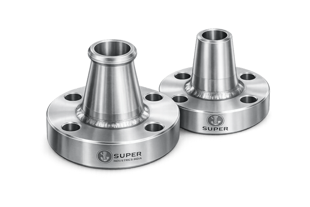
In pressurized piping systems, branch connections represent one of the most critical geometric discontinuities. The introduction of a branch alters the stress distribution within the pipe wall and introduces localized stress intensification.
Weldolet and Nipolet fittings are engineered solutions designed to:
- Create reinforced branch connections from a main pipeline (run pipe)
- Maintain pressure boundary integrity under internal pressure and external loads
- Optimize stress flow between header and branch
- Provide a compact and structurally efficient alternative to fabricated tees
Unlike fabricated or welded stub-in connections, these outlet fittings are designed with integral reinforcement geometry that complies with piping code requirements without requiring additional reinforcement pads.
Functional Purpose in High-Pressure Systems
Branch Connection Creation
Weldolets and Nipolets are used to connect smaller diameter branch pipes to larger diameter headers, typically in:
- Process piping networks
- High-pressure hydrocarbon lines
- Steam and condensate systems
They ensure:
- Structural continuity
- Reinforcement adequacy
- Controlled weld geometry
Reinforced Outlet Design
Branch openings inherently reduce the cross-sectional strength of the header pipe. Weldolets compensate for this by incorporating:
- Increased material thickness at the branch intersection
- Contoured geometry that redistributes stress
- Reinforcement equivalent to or exceeding code requirements
Compact Alternative to Tees
Compared to standard tees:
| Parameter | Weldolet / Nipolet | Reducing Tee |
|---|---|---|
| Weight | Lower | Higher |
| Space Requirement | Minimal | High |
| Fabrication Complexity | Low | Moderate |
| Stress Performance | Optimized | Standard |
Weldolets are especially beneficial where:
- Space constraints exist
- Retrofit connections are required
- Weight reduction is critical (e.g., offshore platforms)
Stress-Optimized Flow Transition
The contoured saddle design allows:
- Smooth transition of flow
- Reduced turbulence compared to sharp-edged branch connections
- Lower erosion and vibration risk
Application Domains
Weldo / Nipolet fittings are extensively used in:
Oil & Gas Pipelines
- Transmission pipelines
- Gathering systems
- Pumping stations
Refineries
- Process unit interconnections
- Utility piping systems
Power Plants
- High-pressure steam lines
- Feedwater systems
LNG Terminals
- Cryogenic service piping
- Gas distribution headers
Petrochemical Plants
- Reactor feed lines
- Chemical transfer systems
Offshore Platforms
- Weight-sensitive piping layouts
- Compact installation environments
High-Pressure Process Piping
- Systems governed by stringent design codes such as ASME B31.3
Engineering Justification Over Alternative Methods
Weldolets vs Stub-In Connections
Stub-in connections involve cutting a hole in the header pipe and welding a branch pipe directly.
Limitations of Stub-In:
- High stress concentration at weld toe
- Requires reinforcement pad (repad)
- Complex weld inspection
- Increased risk of fatigue failure
Weldolet Advantages:
- Integral reinforcement eliminates need for repad
- Reduced stress intensification factor (SIF)
- Controlled weld geometry
- Improved fatigue resistance
Nipolets for Instrumentation & Valve Take-Offs
Nipolets are specifically designed for:
- Small bore connections
- Instrumentation lines
- Pressure taps
- Drain and vent connections
They combine:
- Reinforced outlet body
- Integral nipple (threaded or socket weld)
Advantages:
- Reduced number of weld joints
- Improved leak integrity
- Simplified installation
Space, Weight, and Structural Efficiency
Space Optimization
Weldolets require significantly less axial and radial space compared to tees, making them suitable for:
- Congested piping layouts
- Skid-mounted systems
- Offshore modules
Weight Reduction
Reduced material volume leads to:
- Lower structural load on supports
- Reduced transportation cost
- Improved installation handling
Structural Efficiency
The contoured design:
- Aligns with stress flow lines
- Minimizes abrupt geometric transitions
- Enhances fatigue life under cyclic loading
Code Compliance and Reinforcement Integrity
Weldolet and Nipolet fittings are designed to meet reinforcement requirements as per:
- ASME B31.3 (Process Piping)
- ASME Section VIII (Pressure Vessel Openings)
Key compliance aspects:
- Reinforcement area equivalence
- Pressure boundary continuity
- Acceptable stress intensification factors
These fittings are considered self-reinforced branch connections, eliminating the need for additional reinforcement pads when properly selected.
Super Industries
Global Manufacturer of Heavy & Custom Engineered Fasteners & Flanges
2. Technical Definition
Weldolet Definition
A Weldolet is a forged branch outlet fitting designed for butt-weld connection between a branch pipe and a run pipe.
Key Characteristics:
- Butt-weld outlet
- Contoured base matching header curvature
- Full penetration weld at branch
- Self-reinforced geometry
Functional Role:
- Provides a structurally optimized branch connection
- Maintains pressure integrity
- Reduces stress concentration
Nipolet Definition
A Nipolet is a combination fitting consisting of:
- A Weldolet-type base
- An integral nipple extension
Outlet Types:
- Threaded (NPT / BSP)
- Socket weld
Typical Applications:
- Instrument connections
- Drain points
- Vent connections
- Small bore branch outlets
Self-Reinforced Outlet Concept
The self-reinforced design ensures:
- Additional material thickness at branch junction
- Load distribution across a wider area
- Compliance with reinforcement requirements without external pads
This is achieved through:
- Forged geometry
- Controlled wall thickness distribution
- Contour matching with run pipe
Integral Reinforcement Geometry
Unlike fabricated fittings, Weldolets incorporate:
- Gradual thickness transition
- Smooth curvature blending
- Stress-relieving geometry
This results in:
- Reduced stress gradients
- Improved fatigue performance
- Lower weld stress concentration
Pressure Boundary Continuity
Maintaining pressure boundary integrity is critical.
Weldolet/Nipolet design ensures:
- No abrupt discontinuities
- Full weld penetration at branch
- Uniform stress distribution across weld zones
3. Engineering & Stress Principles
Stress Concentration at Branch Intersections
Branch connections introduce:
- Geometric discontinuity
- Reduced load-bearing cross-section
- Localized stress concentration
Primary stress types:
- Hoop stress (circumferential)
- Longitudinal stress (axial)
- Shear stress at weld interface
Reinforcement Requirements (Code Basis)
Codes such as ASME B31.3 require:
- Replacement of material removed by branch opening
- Adequate reinforcement area within defined limits
Weldolets satisfy this by:
- Providing excess material around opening
- Distributing reinforcement over effective area
Load Distribution Mechanism
Weldolet geometry allows:
- Load transfer from branch to header
- Redistribution of stress away from weld toe
- Balanced stress flow
Internal Pressure Stress Flow
Under internal pressure:
- Hoop stress dominates
- Stress flows around the branch opening
Weldolet design ensures:
- Smooth redirection of stress paths
- Avoidance of sharp stress risers
Hoop vs Longitudinal Stress Interaction
At branch junction:
- Hoop stress is interrupted by opening
- Longitudinal stress must redistribute
Weldolet reinforcement:
- Compensates for hoop stress loss
- Supports axial load transfer
Weld Stress Zones
Critical regions:
- Weld toe (high stress concentration)
- Weld root (penetration quality critical)
- Heat Affected Zone (HAZ)
Weldolets reduce stress at these zones by:
- Providing smoother geometry
- Reducing weld volume compared to stub-in
Stress Intensification Reduction
Stress Intensification Factor (SIF):
- Lower in Weldolets vs fabricated connections
- Improved fatigue life under cyclic loads
Flow Dynamics & Turbulence Reduction
The contoured inlet:
- Reduces flow separation
- Minimizes turbulence
- Limits erosion and vibration
This is critical in:
- High-velocity fluid systems
- Slurry or multiphase flow lines
Comparative Engineering Advantage
| Parameter | Weldolet | Stub-In | Tee |
|---|---|---|---|
| Stress Concentration | Low | High | Moderate |
| Reinforcement | Integral | External Pad | Built-in |
| Installation Complexity | Moderate | High | High |
| Fatigue Resistance | High | Low | Moderate |
4. Applicable Standards (ASTM / ASME / MSS / DIN / EN)
MSS SP-97 — Primary Standard for Branch Outlet Fittings
The governing standard for Weldolet and Nipolet (branch outlet fittings) is:
- MSS SP-97 — Integrally Reinforced Forged Branch Outlet Fittings
Scope and Coverage:
- Dimensional requirements
- Design configuration
- Pressure-temperature ratings
- Manufacturing tolerances
- Marking and identification
Engineering Relevance:
MSS SP-97 defines:
- Self-reinforced geometry criteria
- Compatibility with pipe schedules
- Standard outlet configurations (butt weld, threaded, socket weld)
It forms the baseline for EPC technical approvals and vendor qualification.
ASME B31.3 — Process Piping Code
ASME B31.3 governs:
- Design of piping systems
- Branch reinforcement calculations
- Allowable stresses
- Flexibility and SIF considerations
Relevance to Weldo / Nipolet:
- Defines reinforcement area requirements
- Specifies acceptable stress limits
- Establishes criteria for pressure integrity
ASME Section VIII — Pressure Vessel Code
Applicable when:
- Branch connections are made on pressure vessels
- Nozzle reinforcement is required
Key Considerations:
- Opening reinforcement rules
- Stress analysis around nozzles
- Load transfer to shell
ASTM Material Standards
Material compliance is governed by ASTM specifications:
Carbon Steel
- ASTM A105 (forged fittings, ambient service)
- ASTM A350 LF2 (low temperature service)
Stainless Steel
- ASTM A182 F304 / F304L
- ASTM A182 F316 / F316L
Alloy Steel
- ASTM A182 F11
- ASTM A182 F22
Duplex / Super Duplex
- ASTM A182 F51
- ASTM A182 F53
These standards define:
- Mechanical properties
- Chemical composition
- Heat treatment conditions
DIN / EN Equivalents
For European project compliance:
| ASTM Grade | EN Equivalent |
|---|---|
| A105 | EN 10222-2 C22.8 |
| A182 F304 | EN 10222-5 X5CrNi18-10 |
| A182 F316 | EN 10222-5 X5CrNiMo17-12-2 |
| A350 LF2 | EN 10222-3 P355N |
Pressure-Temperature Compliance Mapping
Standards collectively ensure:
- Pressure rating compatibility
- Temperature resistance
- Material suitability
| Standard | Governs |
|---|---|
| MSS SP-97 | Geometry & design |
| ASME B31.3 | Stress & piping design |
| ASME Section VIII | Pressure vessel integration |
| ASTM | Material integrity |
| EN/DIN | Regional compliance |
5. Material & Grade Options
Material selection directly influences:
- Pressure handling capability
- Corrosion resistance
- Temperature limits
- Lifecycle performance
Carbon Steel
ASTM A105
- Standard forged carbon steel
- Suitable for ambient and moderate temperature service
ASTM A350 LF2
- Designed for low-temperature applications
- Improved impact resistance
Stainless Steel
ASTM A182 F304
- General corrosion resistance
- Suitable for water and mild chemical environments
ASTM A182 F316
- Enhanced resistance to chlorides and acids
- Preferred for offshore and marine systems
Alloy Steel
F11 (Cr-Mo Steel)
- High temperature strength
- Oxidation resistance
F22
- Higher creep resistance
- Used in power plant piping
Duplex & Super Duplex Stainless Steel
- High strength-to-weight ratio
- Superior resistance to stress corrosion cracking
- Excellent performance in aggressive environments
Material Selection Engineering Logic
| Criteria | Material Choice |
|---|---|
| High Pressure | Alloy Steel / Duplex |
| Corrosive Environment | SS316 / Duplex |
| Low Temperature | A350 LF2 |
| High Temperature | F11 / F22 |
| General Service | A105 / SS304 |
Material Comparison Table
| Grade | Yield Strength (MPa) | Tensile Strength (MPa) | Temperature Range | Corrosion Resistance | Typical Industry Use |
|---|---|---|---|---|---|
| A105 | ~250 | ~485 | -29°C to 425°C | Low | Oil & Gas, general piping |
| A350 LF2 | ~250 | ~485 | Down to -46°C | Low | Cryogenic / low temp systems |
| F304 | ~205 | ~515 | Up to 870°C | Moderate | Water, chemical |
| F316 | ~205 | ~515 | Up to 870°C | High | Marine, offshore |
| F11 | ~275 | ~515 | Up to 550°C | Moderate | Power plants |
| F22 | ~415 | ~620 | Up to 600°C | Moderate | High temp service |
| Duplex F51 | ~450 | ~620 | -50°C to 300°C | Very High | Offshore, chemical |
| Super Duplex F53 | ~550 | ~750 | -50°C to 300°C | Excellent | Severe corrosion environments |
6. Heat Treatment Information
Heat treatment ensures:
- Mechanical strength
- Microstructural stability
- Weldability
- Resistance to cracking
Normalizing
- Refines grain structure
- Improves toughness
- Used for carbon steel fittings
Quenching & Tempering (Q&T)
- Increases strength and hardness
- Controls ductility
- Common for alloy steels (F11, F22)
Stress Relieving
- Reduces residual stresses after forging/machining
- Improves dimensional stability
- Critical for thick-section fittings
Solution Annealing (Stainless Steel)
- Dissolves carbides
- Restores corrosion resistance
- Prevents intergranular corrosion
Heat Treatment Impact on HAZ
Heat treatment affects:
- Weld performance
- Crack resistance
- Fatigue life
Proper heat treatment ensures:
- Stable Heat Affected Zone (HAZ)
- Reduced hardness gradients
Impact Testing (Charpy V-Notch)
Applicable for:
- Low temperature service (LF2, Duplex)
Ensures:
- Toughness under impact loading
- Resistance to brittle fracture
7. Manufacturing Process
Manufacturing of Weldo / Nipolet fittings follows a controlled, traceable, and inspection-driven process.
Raw Material Inspection
- Verification of Mill Test Certificates (MTC)
- Chemical composition check
- PMI (Positive Material Identification)
Forging of Outlet Body
- Closed-die forging
- Controlled deformation
- Grain flow alignment with geometry
Contour Machining
- CNC machining of saddle profile
- Matching curvature to run pipe OD
Critical for:
- Proper fit-up
- Stress distribution
Heat Treatment
- Applied as per material grade
- Ensures mechanical property compliance
CNC Machining
- Precision outlet sizing
- Dimensional tolerance control
Threading (For Nipolet)
- NPT / BSP threading
- Gauging as per standards
Bevel Preparation (For Weldolet)
- Butt-weld bevel angle machining
- Ensures weld penetration
Surface Finishing
- Shot blasting
- Surface cleaning
- Coating application
Inspection & Testing
- Dimensional inspection
- NDT (UT, MPI, DPT)
- Hardness testing
Marking & Traceability
- Heat number
- Material grade
- Size and rating
- Manufacturer identification
Ensures:
- Full traceability to raw material
- Compliance with EPC documentation requirements
8. Surface Finish Options
Surface protection is selected based on:
- Environment
- Storage duration
- Corrosion exposure
Anti-Rust Coating
- Temporary protection during transport
- Suitable for carbon steel
Black Oxide Coating
- Minimal corrosion resistance
- Used for indoor applications
Hot-Dip Galvanizing
- Zinc coating for corrosion protection
- Suitable for outdoor and humid environments
Passivation (Stainless Steel)
- Removes free iron
- Enhances corrosion resistance
PTFE / Special Coatings
- Chemical resistance
- Low friction surface
- Used in aggressive environments
Corrosion Protection Logic
| Environment | Recommended Finish |
|---|---|
| Indoor Storage | Black oxide |
| Marine | SS + passivation |
| Outdoor | Galvanized |
| Chemical | PTFE coated |
| Export | Anti-rust oil + wrapping |
Engineering Tables & Dimensional Logic
Size Combination Table (Run Pipe vs Branch Size)
The selection of Weldolet / Nipolet fittings is governed by compatibility between:
- Run pipe (header) size
- Branch size
- Schedule (wall thickness)
- Outlet configuration
Typical Size Combinations
| Run Pipe Size (NPS) | Branch Size (NPS) | Outlet Type | Schedule Compatibility |
|---|---|---|---|
| 2″ | 1/2″ | Nipolet | Sch 80 / 160 |
| 3″ | 1″ | Weldolet | Sch 40 / 80 |
| 4″ | 2″ | Weldolet | Sch 40 / 80 |
| 6″ | 2″ | Weldolet | Sch 80 / 160 |
| 8″ | 3″ | Weldolet | Sch 40 / 80 |
| 10″ | 4″ | Weldolet | Sch 40 / 80 |
| 12″ | 6″ | Weldolet | Sch 40 |
| 16″ | 8″ | Weldolet | Sch 40 |
| 24″ | 12″ | Weldolet | Sch 30 / 40 |
| 36″ | 16″ | Weldolet | Custom |
Engineering Notes:
- Branch size is typically ≤ 50% of run pipe size
- Nipolets are preferred for ≤ 2″ branch connections
- Schedule compatibility must ensure pressure integrity
Dimensional Design Logic (MSS SP-97 Basis)
Key dimensional parameters:
- Run pipe OD matching: Saddle curvature must match header OD
- Branch outlet bore: Matches branch pipe ID
- Reinforcement thickness: Exceeds minimum required area
- Projection (Nipolet): Ensures threading or socket engagement
Critical Considerations:
- Improper contour matching leads to stress concentration
- Dimensional mismatch affects weld fit-up and integrity
- Schedule mismatch can lead to pressure rating inconsistency
Pressure Rating & Temperature Table
Pressure classes for Weldolet / Nipolet fittings are derived from:
- Pipe schedule
- Material strength
- Code allowable stress
Typical Pressure Class Table (Nipolets)
| Class | Approx Pressure Rating (Bar) | Temperature Limit (°C) | Typical Use |
|---|---|---|---|
| 3000 | ~207 bar | Up to 425°C | Instrument connections |
| 6000 | ~414 bar | Up to 425°C | High-pressure piping |
| 9000 | ~620 bar | Up to 425°C | Severe service |
Weldolet Pressure Logic
Weldolets do not have fixed pressure classes. Their rating depends on:
- Matching pipe schedule
- Material allowable stress
- Design temperature
Engineering Principle:
The branch connection must have equal or greater pressure rating than the run pipe.
Reinforcement Area Calculation
Code Basis (ASME B31.3)
Branch reinforcement must satisfy:
Area removed by branch opening ≤ Area available for reinforcement
Fundamental Equation

Where:
- (A_r) = Required reinforcement area
- (A_a) = Available reinforcement area
Detailed Area Components
Area Removed (Ar):

Where:
- (d) = Diameter of branch opening
- (t) = Wall thickness of run pipe
Available Reinforcement Area (Aa):

Where:
- (A_1) = Excess thickness in header
- (A_2) = Excess thickness in branch
- (A_3) = Contribution from Weldolet
Sample Calculation
Given:
- Run pipe: 10″ Sch 40
- Branch: 4″
- Run thickness: 9.27 mm
- Branch opening diameter ≈ 114 mm
Step 1: Area Removed

Step 2: Available Reinforcement
- Header excess thickness: 400 mm²
- Branch excess thickness: 250 mm²
- Weldolet contribution: 600 mm²

Step 3: Compliance Check

Result: Reinforcement requirement satisfied.
Engineering Interpretation
- Weldolet provides significant reinforcement contribution
- Eliminates need for reinforcement pad
- Ensures compliance with ASME B31.3
9. Stress Intensification Factor (SIF) Explanation
Definition
SIF represents:
- Increase in stress due to geometric discontinuity
- Ratio of actual stress to nominal stress
SIF in Branch Connections
Typical SIF values:
| Connection Type | SIF |
|---|---|
| Stub-in | High (2.0–3.0) |
| Tee | Moderate (1.5–2.0) |
| Weldolet | Lower (1.2–1.5) |
Engineering Impact
Higher SIF leads to:
- Increased fatigue risk
- Higher stress concentration
- Reduced lifecycle
Why Weldolets Reduce SIF
- Smooth contour geometry
- Gradual stress transition
- Reduced weld discontinuity
Flexibility Considerations
Weldolets provide:
- Improved flexibility at junction
- Reduced stiffness mismatch
- Better performance under thermal expansion
Mechanical Property Table
| Material | Yield Strength (MPa) | Tensile Strength (MPa) | Hardness (HB) | Elongation (%) | Impact Value (J) |
|---|---|---|---|---|---|
| A105 | 250 | 485 | 187 | 22 | 27 |
| A350 LF2 | 250 | 485 | 187 | 22 | 40 (low temp) |
| F304 | 205 | 515 | 201 | 30 | 50 |
| F316 | 205 | 515 | 217 | 30 | 50 |
| F11 | 275 | 515 | 197 | 20 | 30 |
| F22 | 415 | 620 | 217 | 18 | 27 |
| Duplex F51 | 450 | 620 | 290 | 25 | 60 |
| Super Duplex F53 | 550 | 750 | 310 | 25 | 65 |
Corrosion Resistance Table
| Material | Marine | Acidic | Hydrocarbon | High Temperature |
|---|---|---|---|---|
| Carbon Steel | Poor | Poor | Good | Moderate |
| SS304 | Moderate | Moderate | Good | Good |
| SS316 | Good | Good | Excellent | Good |
| Alloy Steel | Moderate | Poor | Excellent | Excellent |
| Duplex | Excellent | Excellent | Excellent | Moderate |
10. Inspection & Quality Control Methods
Quality assurance for Weldo / Nipolet fittings is aligned with EPC and third-party inspection requirements.
Positive Material Identification (PMI)
- Verifies alloy composition
- Ensures correct material grade
Ultrasonic Testing (UT)
- Detects internal defects
- Ensures forging integrity
Magnetic Particle Inspection (MPI)
- Surface and near-surface crack detection
- Applicable for ferromagnetic materials
Dye Penetrant Testing (DPT)
- Surface defect detection
- Used for stainless steel
Dimensional Inspection
- Verification of MSS SP-97 dimensions
- Tolerance compliance
Hardness Testing
- Confirms heat treatment effectiveness
- Ensures material property compliance
Visual Inspection
- Surface finish
- Machining quality
- Marking verification
Documentation & Certification
EN 10204 Certification
- 3.1 Certificate: Manufacturer test report
- 3.2 Certificate: Third-party validated report
Third-Party Inspection
Common agencies:
- TUV
- SGS
- BV
- DNV
Inspection Scope:
- Raw material verification
- In-process inspection
- Final inspection
- Documentation review
Traceability Requirements
Each fitting is traceable through:
- Heat number
- Batch number
- Material certificate
Ensures:
- Full lifecycle traceability
- Audit readiness for EPC projects
11. Industries Served
Weldo / Nipolet Flanges (Weldolet / Nipolet branch outlet fittings) are deployed across industries where pressure integrity, fatigue resistance, and code-compliant branch reinforcement are mandatory.
Oil & Gas (Upstream, Midstream, Downstream)
Upstream (Exploration & Production)
- Wellhead piping systems
- Flowlines and gathering systems
- High-pressure choke and kill lines
Engineering Requirement:
- High pressure containment
- Resistance to cyclic loading
- Corrosion resistance in sour service (H₂S environments)
Midstream (Transportation & Storage)
- Transmission pipelines
- Pumping and compression stations
Use Cases:
- Instrumentation take-offs via Nipolets
- Branch connections for metering lines
Downstream (Refining & Processing)
- Process piping units
- Reactor feed systems
- Utility networks
Key Requirement:
- Reliable branch connections under high temperature and pressure
Refineries
Weldolets are widely used in:
- Hydrocarbon processing units
- Distillation columns
- Cracking units
Engineering Focus:
- Resistance to thermal cycling
- Compatibility with corrosive process fluids
Petrochemical Plants
Applications include:
- Polymer processing lines
- Chemical transfer piping
- Reactor systems
Material Preference:
- Stainless steel and duplex grades for corrosion resistance
Power Generation
Thermal Power Plants
- High-pressure steam lines
- Feedwater systems
Nuclear Power (Non-safety class applications)
- Auxiliary piping
Critical Requirements:
- High temperature strength
- Creep resistance (F11, F22 materials)
LNG Terminals
- Cryogenic piping systems
- LNG transfer lines
Engineering Requirements:
- Low temperature toughness
- Impact resistance (LF2, Duplex)
Offshore Platforms
- Compact piping layouts
- Weight-sensitive installations
Advantages of Weldolets:
- Reduced structural load
- Minimal space requirement
- Improved fatigue resistance under wave-induced vibrations
Chemical Processing Industry
- Acid transfer lines
- Corrosive fluid systems
Material Selection:
- SS316, Duplex, Super Duplex
Export Capability & Global Supply
Super Industries supplies Weldo / Nipolet Flanges to EPC contractors and project sites across multiple international regions.
Global Supply Regions
- United States
- Europe (EU)
- Middle East (UAE, Saudi Arabia, Qatar, Kuwait)
- Southeast Asia
- Africa
Export Packaging Standards
Packaging is aligned with:
- Long-distance sea freight requirements
- Corrosion protection during transit
Typical Packaging Methods:
- Wooden crates (ISPM 15 compliant)
- Palletized loads
- Individual wrapping with anti-rust protection
- End protection caps for threaded outlets
Documentation Package
Each shipment is supported with EPC-compliant documentation:
- Mill Test Certificates (EN 10204 3.1 / 3.2)
- Inspection Test Plan (ITP)
- Dimensional inspection reports
- NDT reports (UT, MPI, DPT)
- Heat treatment charts
- Material traceability records
Project Logistics Capability
- Bulk supply for large-scale projects
- Lot-wise traceability management
- Coordination with EPC procurement schedules
- Multi-size consolidated shipments
Compliance with Global Procurement Standards
- Alignment with international piping specifications
- Third-party inspection acceptance
- Documentation readiness for consultant approval
12. Procurement & Installation Engineering View
Pre-Installation Considerations
- Verification of material grade (PMI)
- Dimensional check against drawings
- Surface condition inspection
Weld Preparation & Fit-Up
Weldolet Installation
- Proper alignment with run pipe curvature
- Accurate marking of branch location
- Hole cutting on header using approved methods
Fit-Up Requirements:
- Gap control for full penetration weld
- Bevel angle verification
- Root alignment accuracy
Branch Alignment
- Axis of branch must be perpendicular (unless specified otherwise)
- Misalignment leads to:
- Increased stress concentration
- Weld defects
- Reduced fatigue life
Welding Sequence
Typical Procedure:
- Tack welding for positioning
- Root pass (full penetration)
- Fill passes
- Cap pass
Welding Methods:
- GTAW (TIG) for root
- SMAW / FCAW for fill and cap
NDT Requirements During Installation
- Radiography (RT) or Ultrasonic Testing (UT) for weld integrity
- MPI/DPT for surface defects
Inspection Checkpoints
- Pre-weld inspection
- In-process weld inspection
- Post-weld NDT
- Final dimensional verification
Post-Weld Heat Treatment (PWHT)
Applicable when:
- Required by material grade (e.g., alloy steels)
- Specified in project code
Ensures:
- Reduction of residual stress
- Improved weld toughness
Field Installation Practices
- Avoid excessive heat input
- Maintain interpass temperature control
- Ensure clean weld surfaces
- Protect against contamination (especially SS and duplex)
13. Custom Engineering Capabilities
Super Industries supports project-specific customization for Weldo / Nipolet fittings.
Non-Standard Outlet Sizes
- Custom branch-to-run size combinations
- Large diameter headers with small bore outlets
Special Schedule Matching
- Thick wall headers (Sch 160, XXS)
- Custom reinforcement requirements
High-Pressure Custom Outlets
- Beyond standard MSS SP-97 configurations
- Designed for severe service conditions
Special Threading Options (Nipolet)
- NPT (ASME B1.20.1)
- BSP (BS standards)
- Custom threading as per project requirement
Large Diameter Branch Solutions
- Engineered outlet fittings for large pipelines
- Stress-optimized geometry for high load conditions
Project-Specific Engineering Support
- Dimensional customization
- Material selection assistance
- Code compliance verification
Final Engineering Conclusion
Weldo / Nipolet Flanges (Weldolet / Nipolet branch outlet fittings) are critical engineered components for branch connections in pressurized piping systems.
Their adoption in EPC projects is based on:
- Self-reinforced design compliant with ASME B31.3
- Reduced stress intensification compared to stub-in connections
- Optimized geometry for pressure and fatigue performance
- Compact and weight-efficient configuration
- Compatibility with high-pressure, high-temperature systems
From an engineering evaluation perspective, these fittings provide:
- Reliable pressure boundary continuity
- Controlled weld geometry
- Reduced installation complexity
- Long-term structural integrity under cyclic loading
Super Industries manufactures these fittings in accordance with:
- MSS SP-97 dimensional standards
- ASTM material specifications
- ASME piping design principles
with full traceability, inspection compliance, and export-ready documentation aligned to global EPC project requirements.