
LONG WELD NECK FLANGES
Super Industries
“Global Manufacturer of Heavy & Custom Engineered Fasteners for Oil & Gas, Power & EPC Contractors.”
1. Industry Context & System Relevance
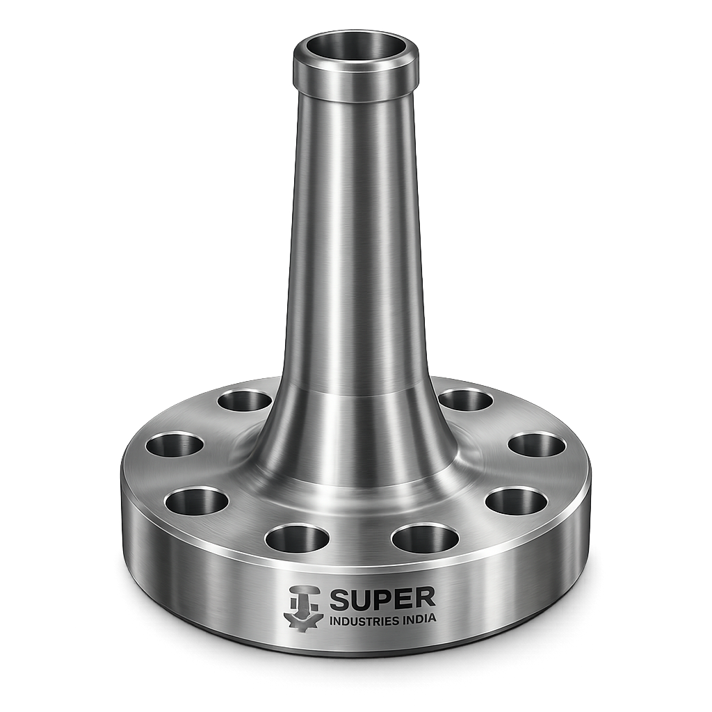
In pressure vessel and high-integrity piping systems, the interface between the vessel shell and external piping is one of the most critical stress zones in the entire system. This junction is subject to combined loading conditions including:
- Internal pressure-induced stresses
- External piping loads (forces and moments)
- Thermal expansion and contraction
- Cyclic fatigue loading
- Structural discontinuity effects
Traditionally, nozzle connections in pressure vessels are designed using:
- A set-in or set-on nozzle
- Reinforcement pad (repad)
- Welded attachments with multiple joints
However, this conventional approach introduces:
- Multiple weld seams
- Increased inspection complexity
- Higher stress concentration zones
- Greater probability of fabrication defects
- Increased NDT scope and cost
Role of Long Weld Neck Flanges in Modern Pressure Systems
Long Weld Neck Flanges (LWN Flanges)—also referred to as:
- Heavy Barrel Flanges
- Integrally Reinforced Flanges
- Pressure Vessel Nozzle Flanges
- Self-Reinforced Nozzle Flanges
—are engineered to replace traditional nozzle + repad configurations by integrating reinforcement within the flange geometry itself.
Primary Functional Role
An LWN flange acts simultaneously as:
- Pressure boundary component
- Nozzle extension
- Reinforcement element (UG-37 compliance)
- Load transfer medium between piping and vessel shell
This integration eliminates the need for external reinforcement pads while achieving equivalent or superior structural performance.
Applications in Critical Systems
LWN flanges are deployed in high-consequence environments where:
- Failure risk must be minimized
- Inspection accessibility is limited
- High loads and cyclic conditions exist
Typical Application Areas
- High-pressure reactors
- Hydroprocessing units
- Fractionation columns
- Heat exchangers (channel nozzles)
- LNG cryogenic systems
- Offshore topside modules
- Power plant pressure vessels
- Ammonia and urea plants
Why LWN Flanges Are Used Instead of Standard Weld Neck Flanges
| Parameter | Standard WN Flange | Long Weld Neck Flange |
|---|---|---|
| Hub Length | Short | Extended (custom engineered) |
| Reinforcement | None | Built-in (integral) |
| Nozzle Role | Connection only | Structural + pressure boundary |
| Stress Distribution | Localized | Gradual transition |
| Fatigue Resistance | Moderate | High |
| Suitability for Pressure Vessels | Limited | Primary choice |
Replacement of Reinforcement Pad (UG-37 Context)
Under ASME Section VIII Division 1, nozzle reinforcement is governed by:
- Area replacement method (UG-37)
In traditional design:
- Area removed from shell is compensated using repad or excess thickness
In LWN design:
- Reinforcement is achieved through extended barrel geometry
- Material is distributed along the load path rather than concentrated locally
Engineering Advantage
- Eliminates stress discontinuity caused by repads
- Removes crevice zones (corrosion risk)
- Reduces weld count (improves reliability)
System-Level Benefits
1. Stress Redistribution
The extended hub provides a gradual transition:
- From flange thickness → barrel → vessel shell
- Reducing stress intensification factors (SIF)
2. Reduced Weld Joints
- No repad welding
- Single primary weld at shell interface
3. Inspection Efficiency
- Fewer welds = reduced RT/UT scope
- Improved accessibility
4. High-Cycle Fatigue Suitability
- Critical for:
- Thermal cycling systems
- Pressure fluctuation environments
Super Industries
Global Manufacturer of Heavy & Custom Engineered Fasteners & Flanges
2. Technical Definition
What is a Long Weld Neck Flange (LWN)?
A Long Weld Neck Flange (LWN Flange) is:
A forged, integrally reinforced flange with an extended tapered hub (barrel), designed to function as a self-reinforced pressure vessel nozzle, engineered to transfer loads efficiently between piping and vessel shell.
Key Structural Features
- Extended tapered hub (long neck / barrel)
- Bore matching nozzle internal diameter
- Flange face (RF / RTJ / custom)
- Thickened section for load-bearing
- Custom geometry based on design conditions
Comparison: WN vs LWN Flange
| Feature | Weld Neck Flange | Long Weld Neck Flange |
|---|---|---|
| Hub Length | Short | Long (engineered) |
| Application | Piping systems | Pressure vessels |
| Reinforcement | External required | Integral |
| Design Standard | ASME B16.5 | Custom + B16.5 interface |
| Stress Handling | Limited | Advanced |
| Load Transfer | Localized | Distributed |
Barrel Length vs Standard Hub
The defining characteristic of LWN flange is the barrel length, which is:
- Significantly longer than standard WN hub
- Designed based on:
- Shell thickness
- Design pressure
- External loads
Bore Matching
- Bore is precision machined
- Matches nozzle internal diameter
- Ensures:
- Smooth flow transition
- Reduced turbulence
- No internal stress raisers
Integration with Vessel Shell
The LWN flange is welded directly to the vessel shell:
- Typically via full penetration weld
- Designed for:
- Load continuity
- Structural integrity
- Code compliance
Facing Options
- Raised Face (RF)
- Ring Type Joint (RTJ)
- Custom sealing profiles
3. Engineering & Stress Principle (CRITICAL SECTION)
Stress Concentration at Nozzle-to-Shell Junction
The nozzle-shell intersection is inherently a geometric discontinuity, leading to:
- Stress intensification
- Bending effects
- Localized deformation
Sources of Stress
- Internal pressure → membrane stress
- External loads → bending stress
- Thermal gradients → secondary stress
- Cyclic loading → fatigue stress
Membrane Stress vs Bending Stress
Membrane Stress
- Uniform stress across thickness
- Caused by internal pressure
Bending Stress
- Varies across thickness
- Caused by:
- External piping loads
- Structural constraints
Problem with Conventional Nozzle Design
Traditional repad design creates:
- Abrupt thickness transitions
- Weld-induced stress concentration
- Local stiffness variation
This results in:
- High Stress Intensification Factors (SIF)
- Fatigue crack initiation points
How LWN Flanges Solve This
1. Gradual Stress Transition
The extended barrel provides:
- Smooth thickness transition
- Reduced geometric discontinuity
2. Load Distribution Along Axis
Instead of concentrating stress at weld:
- Loads are distributed along the barrel length
- Reduces peak stress values
3. Reduction in Stress Intensification
LWN design lowers:
- Local peak stresses
- Stress gradients
4. Improved Fatigue Performance
- Lower stress concentration → longer fatigue life
- Suitable for cyclic service
External Load Consideration
LWN flanges are designed to handle:
- Axial forces
- Shear forces
- Bending moments
These loads originate from:
- Connected piping systems
- Thermal expansion
- Structural misalignment
Pressure-Induced Stress Behavior
Under internal pressure:
- Hoop stress develops in shell
- Nozzle introduces stress disturbance
LWN flange:
- Redistributes these stresses
- Maintains continuity
Transition from Flange to Shell Thickness
A critical design feature:
- Gradual taper from flange thickness → shell thickness
- Prevents sudden stiffness change
Fatigue Resistance Under Cyclic Loading
LWN flanges are preferred in:
- Start-stop operations
- Thermal cycling
- Pulsating pressure systems
Because:
- Reduced SIF
- Improved stress distribution
- Lower crack initiation probability
Engineering Summary of Stress Behavior
| Parameter | Conventional Nozzle | LWN Flange |
|---|---|---|
| Stress Concentration | High | Low |
| Weld Count | Multiple | Single |
| Fatigue Resistance | Moderate | High |
| Load Transfer | Localized | Distributed |
| Structural Integrity | Dependent on welds | Integral |
4. Applicable Standards & Code Framework
Long Weld Neck Flanges (LWN Flanges) operate at the intersection of pressure vessel design, piping interface standards, and material specifications. Unlike standard flanges, they are not fully governed by a single dimensional standard and must be engineered using a combination of codes.
Primary Governing Codes
ASME Section VIII Division 1 — Pressure Vessel Design
This is the core design basis for LWN flanges when used as pressure vessel nozzles.
Relevant clauses:
- UG-37 → Reinforcement of openings (area replacement method)
- UG-45 → Nozzle neck thickness requirements
- Appendix 1-7 → Reinforcement calculations
- Appendix 46 / WRC references → External load considerations
Relevance to LWN Flanges:
- LWN flange barrel acts as integral reinforcement area
- Eliminates need for repad when properly designed
- Must satisfy required reinforcement area under all load cases
ASME B16.5 — Flange Interface Standard
Although LWN flanges are custom-engineered, the flange-facing interface typically complies with B16.5:
- Bolt circle dimensions
- Number of bolts
- Facing types (RF / RTJ)
- Pressure class reference (150# to 2500# equivalent)
Important Clarification:
Only the flange interface follows B16.5.
The barrel length, thickness, and geometry are fully custom.
ASME B31.3 — Process Piping
Provides guidance for:
- External piping loads (forces & moments)
- Allowable stresses
- Flexibility and thermal expansion
Relevance:
- Nozzle loads transferred from piping must be evaluated
- LWN flange must withstand these loads without overstress
WRC Bulletins (537 / 107 / 297)
Used for:
- Local stress evaluation at nozzle-shell junction
- External load stress analysis
ASTM Material Standards
Define:
- Chemical composition
- Mechanical properties
- Heat treatment requirements
Critical Engineering Note
⚠️ LWN Flanges are not catalog products.
They are:
- Design-specific components
- Engineered per vessel thickness, pressure, and load conditions
- Verified through calculation or FEA where required
5. Material & Grade Selection
Material selection for LWN flanges is governed by:
- Design pressure and temperature
- Corrosion environment
- Weldability requirements
- Toughness requirements (especially low temperature)
Primary Material Categories
1. Carbon Steel
ASTM A105
- Standard forging material for ambient to moderate temperature
- Good machinability and weldability
ASTM A350 LF2
- Low-temperature carbon steel
- Improved impact toughness
- Suitable for sub-zero service
2. Stainless Steel
ASTM A182 F304 / F304L
- General corrosion resistance
- Suitable for chemical environments
ASTM A182 F316 / F316L
- Enhanced resistance to chlorides
- Preferred for marine and offshore
3. Alloy Steel
ASTM A182 F11 / F22
- High-temperature strength
- Creep resistance
- Used in power plants and refineries
4. Duplex & Super Duplex Stainless Steel
- High strength + corrosion resistance
- Excellent resistance to stress corrosion cracking
- Used in offshore and aggressive environments
MATERIAL COMPARISON TABLE
| Material Grade | Yield Strength (MPa) | Tensile Strength (MPa) | Temperature Range | Corrosion Resistance | Typical Application |
|---|---|---|---|---|---|
| A105 | ~250 | ~485 | -29°C to 425°C | Low | General refinery service |
| A350 LF2 | ~250 | ~485 | Down to -46°C | Low | Low-temperature vessels |
| F304 | ~205 | ~515 | Up to 870°C | Moderate | Chemical processing |
| F316 | ~205 | ~515 | Up to 870°C | High | Offshore / marine |
| F11 | ~275 | ~585 | Up to 540°C | Moderate | Power plants |
| F22 | ~415 | ~620 | Up to 600°C | Moderate | High-temp reactors |
| Duplex | ~450 | ~620 | -50°C to 300°C | Very High | Offshore / subsea |
Material Selection Engineering Considerations
1. Strength vs Thickness
Higher strength materials:
- Reduce required thickness
- Improve weight efficiency
2. Corrosion Behavior
- Carbon steel requires coating or lining
- Stainless and duplex provide inherent resistance
3. Temperature Resistance
- Alloy steels for high temperature
- LF2 for low temperature
4. Weldability
- Carbon steels → easier
- Duplex → controlled welding required
6. Heat Treatment
Heat treatment is critical for:
- Mechanical performance
- Residual stress control
- Microstructure uniformity
Common Heat Treatment Processes
1. Normalizing
- Refines grain structure
- Improves uniformity
- Used for carbon steels
2. Quenching & Tempering (Q&T)
- Increases strength and toughness
- Used for alloy steels
3. Stress Relieving
- Reduces residual stresses from forging and machining
- Essential for thick sections (LWN barrels)
4. Solution Annealing (Stainless Steel)
- Restores corrosion resistance
- Removes carbide precipitation
Heat Treatment Engineering Impact
| Process | Effect |
|---|---|
| Normalizing | Grain refinement |
| Q&T | High strength + toughness |
| Stress Relieving | Reduced distortion risk |
| Solution Annealing | Corrosion resistance restoration |
7. Manufacturing Process
LWN flanges are manufactured through a precision-controlled, multi-stage process, combining heavy forging with deep machining.
Step-by-Step Manufacturing Flow
1. Raw Material Selection
- Certified forging-grade billets
- Fully traceable heat numbers
- Verified chemical composition
2. Heavy Forging (Open Die Forging)
- Performed under controlled temperature
- Produces:
- Dense grain structure
- Directional strength
- Improved fatigue resistance
3. Primary Heat Treatment
- Normalizing / Q&T depending on material
- Achieves required mechanical properties
4. Rough Machining
- Removal of excess material
- Establishes reference geometry
5. Deep Bore Machining
- Precision boring to match nozzle ID
- Critical for:
- Flow efficiency
- Stress reduction
6. Barrel Profiling
- Tapered hub machining
- Controlled transition from flange to shell thickness
7. Flange Facing Machining
- RF (Raised Face)
- RTJ groove machining
Ensures:
- Gasket seating integrity
- Surface finish compliance
8. Drilling
- Bolt hole drilling per B16.5 pattern
- Precision alignment critical
9. Final Machining
- Dimensional finishing
- Tolerance control
- Surface integrity
10. Final Inspection Preparation
- Cleaning
- Marking
- Documentation alignment
Manufacturing Engineering Considerations
1. Grain Flow Orientation
Forging ensures:
- Grain flow follows load path
- Improves fatigue resistance
2. Machining Accuracy
Critical for:
- Flange alignment
- Leak prevention
3. Thickness Control
Essential for:
- Pressure integrity
- Reinforcement compliance
Surface Finish & Protection
Surface finishing depends on:
- Service environment
- Storage conditions
- Export requirements
Available Surface Finishes
1. Anti-Rust Coating
- Temporary protection
- Used for carbon steel
2. Painting
- Epoxy or industrial coatings
- Used for atmospheric protection
3. Galvanizing
- Zinc coating
- Limited use (not typical for high-temp service)
4. Passivation (Stainless Steel)
- Enhances corrosion resistance
- Removes surface contaminants
Surface Finish Engineering Consideration
- Must not interfere with gasket seating
- Facing area remains precisely machined
8. Inspection & Quality Control
Inspection of LWN flanges is critical due to:
- High-pressure service
- Structural role as nozzle
Inspection Methods
1. PMI (Positive Material Identification)
- Confirms material grade
2. Ultrasonic Testing (UT)
- Detects internal flaws
- Essential for heavy sections
3. Magnetic Particle Inspection (MPI)
- Detects surface cracks (ferromagnetic materials)
4. Dye Penetrant Testing (DPT)
- Surface crack detection (non-magnetic materials)
5. Dimensional Inspection
- Critical tolerances:
- Bore diameter
- Barrel thickness
- Flange face
6. Hardness Testing
- Verifies heat treatment effectiveness
Documentation & Certification
EN 10204 Standards
- 3.1 Certificate → Manufacturer certification
- 3.2 Certificate → Third-party witnessed
Third-Party Inspection (TPIA)
Common agencies:
- Lloyd’s
- BV
- TUV
- SGS
Inspection Dossier Includes
- Material test certificates
- Heat treatment records
- NDT reports
- Dimensional reports
- Marking traceability
A. Typical LWN Design Parameters Table
The defining feature of an LWN flange is its custom-engineered barrel, which replaces conventional reinforcement.
| Nozzle Size (NPS) | Barrel Length (mm) | Barrel OD (mm) | Flange Thickness (mm) | Equivalent Pressure Class | Typical Application |
|---|---|---|---|---|---|
| 2” | 150 – 300 | 90 – 140 | 25 – 50 | 600# – 1500# | Instrument nozzles |
| 4” | 250 – 450 | 140 – 220 | 40 – 80 | 900# – 2500# | Process lines |
| 6” | 300 – 600 | 200 – 320 | 60 – 120 | 1500# – 2500# | Reactor nozzles |
| 8” | 400 – 800 | 260 – 400 | 80 – 150 | 1500# – 2500# | Column nozzles |
| 12” | 600 – 1200 | 350 – 550 | 120 – 220 | 900# – 2500# | Heat exchangers |
| 16” | 800 – 1500 | 450 – 700 | 150 – 300 | 600# – 1500# | Large vessel nozzles |
Engineering Interpretation
- Barrel Length → Primary reinforcement contributor
- Barrel OD → Controls section modulus and stiffness
- Flange Thickness → Governs gasket seating and bolt load
- Pressure Class → Interface reference only (not design limit)
B. Pressure & Temperature Consideration Table
Material and geometry must satisfy combined pressure-temperature limits.
| Material | Max Design Pressure (Indicative) | Max Temperature | Low Temperature Limit | Service Suitability |
|---|---|---|---|---|
| A105 | High (up to ~250 bar*) | ~425°C | -29°C | General refinery |
| A350 LF2 | Moderate | ~350°C | -46°C | Cryogenic / LNG |
| F304 | Moderate | ~870°C | -196°C | Chemical |
| F316 | Moderate | ~870°C | -196°C | Offshore |
| F11 | High | ~540°C | ~0°C | Power plants |
| F22 | Very High | ~600°C | ~0°C | High-temp reactors |
| Duplex | High | ~300°C | -50°C | Offshore / subsea |
*Actual allowable pressure depends on thickness and code calculation.
Engineering Considerations
- Pressure rating is geometry dependent, not just material
- Temperature affects:
- Allowable stress
- Creep behavior
- Fatigue life
C. Bolt Load Calculation
Bolt load ensures:
- Gasket seating during installation
- Leak-tight performance during operation
1. Gasket Seating Load
W_{m1} = \pi \cdot b \cdot G \cdot y
Where:
- ( W_{m1} ) = Minimum bolt load for gasket seating
- ( b ) = Effective gasket width
- ( G ) = Gasket mean diameter
- ( y ) = Gasket seating stress
2. Operating Load
W_{m2} = \frac{\pi G^2 P}{4} + 2 \pi b G m P
Where:
- ( P ) = Internal pressure
- ( m ) = Gasket factor
3. Design Condition
[
W_{bolt} \geq \max(W_{m1}, W_{m2})
]
Engineering Interpretation
- LWN flanges typically require higher bolt loads due to:
- Larger gasket diameters
- Higher pressure service
- Proper bolt load ensures:
- No flange rotation
- No leakage under load
D. Nozzle Stress Consideration
Stress Categories at Nozzle
- Membrane Stress (Primary)
- Bending Stress (Secondary)
- Peak Stress (Local)
Stress Intensification Factors (SIF)
Conventional nozzles:
- High SIF due to abrupt geometry
LWN flanges:
- Reduced SIF due to gradual taper
Load Transfer Mechanism
Without LWN
- Load concentrated at weld
- High local stress
With LWN
- Load distributed along barrel
- Reduced peak stress
External Load Components
- Axial force (Fx)
- Shear force (Fy, Fz)
- Bending moment (Mx, My, Mz)
Engineering Outcome
LWN flanges:
- Improve load distribution
- Reduce local stress peaks
- Enhance fatigue resistance
E. Mechanical Properties Table
| Material | Yield Strength (MPa) | Tensile Strength (MPa) | Elongation (%) | Hardness (HB) | Impact Resistance |
|---|---|---|---|---|---|
| A105 | ~250 | ~485 | ~20 | 120–180 | Moderate |
| A350 LF2 | ~250 | ~485 | ~22 | 120–180 | High |
| F304 | ~205 | ~515 | ~40 | ≤187 | Excellent |
| F316 | ~205 | ~515 | ~40 | ≤187 | Excellent |
| F11 | ~275 | ~585 | ~20 | 140–200 | Moderate |
| F22 | ~415 | ~620 | ~18 | 160–220 | Moderate |
| Duplex | ~450 | ~620 | ~25 | 200–300 | High |
Engineering Insight
- Higher yield strength → improved load capacity
- Higher elongation → better ductility
- Impact resistance → critical for low temperature service
F. Corrosion Resistance Table
| Material | General Corrosion | Chloride Resistance | SCC Resistance | Marine Suitability |
|---|---|---|---|---|
| A105 | Low | Poor | Poor | Not suitable |
| A350 LF2 | Low | Poor | Poor | Not suitable |
| F304 | Moderate | Moderate | Low | Limited |
| F316 | High | High | Moderate | Good |
| Duplex | Very High | Excellent | Excellent | Excellent |
Engineering Interpretation
- Duplex materials are preferred for:
- Offshore platforms
- Seawater exposure
- Carbon steel requires:
- Coating
- Corrosion allowance
G. Flange Rotation & Leakage Consideration
Problem
Under bolt load + pressure:
- Flange may rotate
- Gasket stress reduces
- Leakage risk increases
LWN Advantage
- High stiffness due to thick hub
- Reduced rotation
- Improved sealing integrity
H. Thermal Load Consideration
Sources
- Differential expansion
- Temperature gradients
Effect
- Induces secondary stresses
- Can cause fatigue
LWN Response
- Gradual geometry reduces stress concentration
- Better thermal stress distribution
I. Reinforcement Area Concept (UG-37 Alignment)
Basic Principle
Area removed by opening must be compensated.
In LWN Flange
- Reinforcement is provided by:
- Barrel thickness
- Extended length
Engineering Advantage
- Distributed reinforcement
- Eliminates localized overstress
J. Comparative Engineering Summary
| Parameter | Conventional Nozzle | LWN Flange |
|---|---|---|
| Reinforcement | Repad | Integral |
| Stress Distribution | Localized | Distributed |
| Weld Count | High | Low |
| Fatigue Life | Moderate | High |
| Inspection | Complex | Simplified |
9. Procurement Engineering Perspective
From an EPC and pressure vessel project standpoint, Long Weld Neck Flanges (LWN Flanges) are categorized as:
- Engineered-to-order components
- Critical pressure boundary items
- Inspection-intensive deliverables
Unlike standard ASME B16.5 flanges, procurement of LWN flanges requires multi-disciplinary coordination between:
- Mechanical design engineers
- Piping stress teams
- Vessel designers
- Procurement engineers
- Third-party inspectors
Key Procurement Inputs Required
For accurate manufacturing and compliance, the following inputs are mandatory:
1. Process & Design Data
- Design pressure and temperature
- Operating pressure and temperature
- Corrosion allowance
- Cyclic service requirements
2. Vessel Parameters
- Shell thickness
- Vessel internal diameter
- Material of construction
- Joint efficiency
3. Nozzle & Piping Loads
- Axial loads (Fx)
- Shear loads (Fy, Fz)
- Bending moments (Mx, My, Mz)
Typically derived from:
- Piping stress analysis (CAESAR II or equivalent)
4. Flange Interface Requirements
- Facing type (RF / RTJ)
- Pressure class reference
- Bolt size and quantity
- Gasket type
5. Material Specifications
- ASTM grade
- Impact test requirements
- PWHT requirements
6. Inspection Requirements
- NDT scope (UT / RT / MPI / DPT)
- Third-party inspection (TPIA)
- Documentation level (3.1 / 3.2)
Procurement Deliverables
A complete LWN flange supply package typically includes:
- General Arrangement Drawing (GA)
- Manufacturing drawing with dimensions
- Reinforcement calculations (UG-37 basis)
- Material Test Certificates (MTC)
- Heat treatment charts
- NDT reports
- Dimensional inspection reports
- Marking and traceability records
10. Installation & Field Engineering Practices
Correct installation of Long Weld Neck Flanges is essential to maintain:
- Pressure integrity
- Alignment accuracy
- Long-term fatigue performance
1. Welding to Vessel Shell
- Full penetration weld (butt weld)
- Weld procedure qualified as per ASME Section IX
- Preheat and PWHT as per material specification
2. Alignment Control
Critical requirements:
- Flange face perpendicularity
- Nozzle alignment with piping axis
- Avoidance of forced fit-up
Misalignment may result in:
- Secondary stresses
- Bolt load redistribution
- Leakage risk
3. Gasket Selection
Selection depends on:
- Pressure class
- Temperature
- Fluid type
Typical gasket types:
- Spiral wound gasket (SWG)
- Ring Type Joint (RTJ) for high-pressure service
4. Bolt Tightening Procedure
- Controlled torque application
- Cross-pattern tightening sequence
- Multiple passes (incremental loading)
Objective:
- Uniform gasket compression
- Prevention of flange rotation
5. Field Inspection
Includes:
- Visual inspection of welds
- NDT (as required)
- Bolt torque verification
- Leak testing (hydrostatic / pneumatic)
Installation Risk Considerations
| Risk | Cause | Mitigation |
|---|---|---|
| Flange leakage | Improper bolt load | Controlled tightening |
| Weld cracking | Thermal stress | Proper PWHT |
| Misalignment | Poor fit-up | Precision installation |
| Fatigue failure | Cyclic loads | Correct design + alignment |
11. Custom Engineering Capabilities
Long Weld Neck Flanges are inherently custom-engineered products. Capability is defined by ability to design and manufacture based on project-specific conditions.
Engineering Scope Includes
1. Full Custom LWN Design
- Based on:
- Pressure
- Temperature
- Nozzle loads
- Vessel geometry
2. Heavy Wall Barrel Design
- Thick-section forging
- High-pressure suitability
3. High-Pressure Applications
- Equivalent to ASME 1500#–2500# and beyond
- Reactor and hydrocracker service
4. RTJ Groove Machining
- Precision machining
- Tight tolerance control
5. Large Diameter Nozzles
- Up to heavy vessel nozzle sizes
- Requires advanced machining capability
12. Industries Served
Long Weld Neck Flanges are used in sectors where:
- Pressure integrity is critical
- Failure consequences are high
- Engineering validation is mandatory
Primary Industries
1. Oil & Gas
- Upstream processing
- Downstream refining
- Hydrocarbon handling systems
2. Refineries
- Hydrocrackers
- Reformers
- Distillation units
3. Petrochemicals
- Chemical reactors
- High-temperature process units
4. LNG & Cryogenic Systems
- Low-temperature vessels
- LNG storage and transfer
5. Offshore Platforms
- Topside modules
- Subsea systems
6. Power Plants
- Boiler systems
- High-pressure steam lines
13. Export Capability & Supply Chain
LWN flanges are typically supplied for international EPC projects, requiring:
- Compliance with global standards
- Robust documentation
- Secure logistics
Export Engineering Requirements
1. Documentation
- EN 10204 3.1 / 3.2 certification
- NDT reports
- Inspection release notes
2. Packaging
- Wooden crates (fumigated)
- Machined surface protection
- Moisture-resistant wrapping
3. Marking & Traceability
- Heat number stamping
- Material grade identification
- Size and pressure class marking
4. Logistics Considerations
- Heavy weight handling
- Oversized cargo management
- Export compliance documentation
Quality Assurance in Global Supply
To meet EPC expectations, supplied LWN flanges must ensure:
- Full traceability from raw material to final product
- Compliance with approved drawings
- Verified mechanical properties
- Documented inspection records
Final Engineering Summary
Long Weld Neck Flanges (LWN Flanges) represent a structural solution for pressure vessel nozzle connections, integrating:
- Reinforcement
- Load transfer
- Pressure containment
into a single forged component.
Engineering Advantages
- Eliminates reinforcement pads
- Reduces weld count
- Improves stress distribution
- Enhances fatigue resistance
- Simplifies inspection
Design Responsibility
Successful implementation requires:
- Accurate input data
- Code-compliant design calculations
- Controlled manufacturing
- Verified installation practices
EPC-Level Conclusion
For pressure vessel applications involving:
- High pressure
- High temperature
- Cyclic loading
- Critical service
Long Weld Neck Flanges provide a technically robust and code-aligned alternative to conventional nozzle reinforcement methods.
End of Document — EPC Technical Reference Page
This document is structured to support:
- Consultant evaluation
- EPC procurement decisions
- Pressure vessel design validation
- Inspection and compliance review