
Blind Flanges
Engineering Reference & System Role
Super Industries
“Global Manufacturer of Heavy & Custom Engineered Fasteners for Oil & Gas, Power & EPC Contractors.”
1. Industry Context & System Relevance
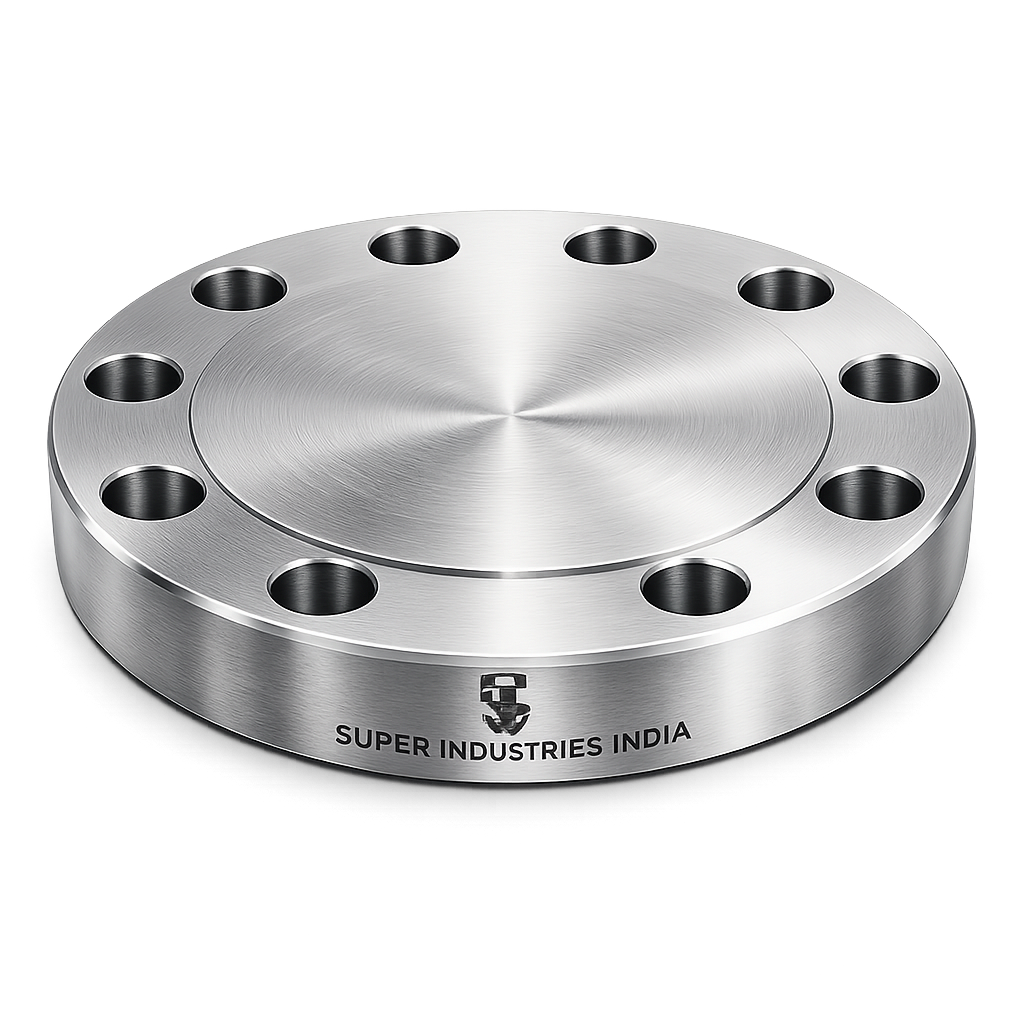
Blind Flanges are a critical component in pressure-retaining piping systems, designed to provide positive isolation at pipeline ends, vessel nozzles, and branch connections. Unlike flow-bearing flanges, Blind Flanges are solid closures, engineered to withstand full system pressure without any bore.
Functional Role in Piping Systems
Blind Flanges serve four primary engineering functions:
1. Line Termination and Isolation
Blind Flanges are used to permanently or temporarily seal pipeline ends, ensuring no fluid transmission beyond the termination point. This is essential in:
- Dead-end piping systems
- Future expansion headers
- Shutdown isolation points
2. Pressure Boundary Sealing
They act as primary pressure-retaining barriers, forming part of the pressure envelope in accordance with ASME piping codes.
3. Provision for Future Expansion
Unlike welded closures, Blind Flanges allow future extension of pipelines by simply removing the flange and extending the line. This is critical in:
- Modular plant design
- EPC phased construction
- Brownfield expansions
4. Hydrostatic Testing Closures
Blind Flanges are extensively used during:
- Hydrostatic pressure testing
- Leak testing of pipelines
- Commissioning activities
They enable controlled pressurization and isolation during testing operations.
Application Across Industrial Sectors
Blind Flanges are used in high-integrity piping systems across:
Oil & Gas Pipelines
- Pipeline termination points
- Pigging launcher/receiver closures
- Maintenance isolation
Refineries
- Process line isolation
- Shutdown systems
- Pressure vessel nozzle closures
Power Plants
- Boiler piping systems
- Steam lines
- Turbine auxiliary systems
LNG Terminals
- Cryogenic line terminations
- Storage tank nozzle closures
Petrochemical Plants
- Reactor isolation
- High-pressure process lines
Water Transmission Systems
- Large diameter pipeline ends
- Pump station isolation
Process Piping Networks
- Chemical processing plants
- Fertilizer plants
- Industrial fluid systems
Why Blind Flanges Instead of Caps or Welded Closures
Blind Flanges are selected over welded caps or closures due to their operational flexibility and engineering advantages.
Comparison: Blind Flanges vs Welded Caps
| Parameter | Blind Flanges | Welded Caps |
|---|---|---|
| Removability | Fully removable | Permanent |
| Maintenance Access | Easy | Requires cutting |
| Inspection Capability | High | Limited |
| Expansion Flexibility | Excellent | None |
| Installation | Bolted | Welded |
Key Engineering Advantages
- Enables non-destructive disassembly
- Allows periodic inspection of internal piping
- Eliminates need for cutting and rewelding
- Supports future tie-ins and system modifications
From an EPC perspective, Blind Flanges provide lifecycle cost advantages despite higher initial material cost.
Super Industries
Global Manufacturer of Heavy & Custom Engineered Fasteners & Flanges
2. Technical Definition of Blind Flanges
A Blind Flange is defined as:
A solid, non-bored, pressure-retaining flange used to close the end of a piping system or pressure vessel opening, designed to withstand internal pressure through bolted joint integrity.
Core Design Characteristics
- No central bore
- Fully solid disc construction
- Machined flange faces for gasket seating
- Bolt holes aligned with mating flange
- Designed per pressure class requirements
Functional Elements
1. Flange Body
The main disc that resists internal pressure.
2. Bolt Circle
Holes drilled to match mating flange for bolted assembly.
3. Sealing Face
Machined surface that interfaces with gasket for leak-tight sealing.
Facing Types
Blind Flanges are manufactured with standard flange facings:
Flat Face (FF)
- Used with cast iron or low-pressure systems
- Full face gasket contact
Raised Face (RF)
- Most common configuration
- Concentrates gasket load on smaller area
- Improves sealing efficiency
Ring Type Joint (RTJ)
- Used in high-pressure applications
- Metal-to-metal sealing via RTJ gasket
- Designed for critical services (oil & gas, high temperature)
Pressure Boundary Integrity
Blind Flanges must withstand:
- Internal pressure forces
- Gasket seating stresses
- Bolt preload forces
- Thermal expansion effects
Unlike flow flanges, Blind Flanges experience maximum internal pressure loading across the full area, making them structurally more demanding.
3. Engineering & Sealing Principle
The performance of Blind Flanges depends on the interaction between bolt preload, gasket compression, and internal pressure forces.
Bolt Preload Mechanics
Bolts are tightened to generate preload force, which:
- Compresses the gasket
- Creates a leak-tight seal
- Resists separation due to internal pressure
Key Principle:
Bolt preload must exceed the hydrostatic end force acting on the blind surface.
Gasket Compression Behavior
The gasket acts as a deformable sealing element, filling surface irregularities.
Critical Parameters:
- Minimum seating stress
- Operating sealing stress
- Creep relaxation
- Temperature stability
Internal Pressure vs Sealing Stress
When internal pressure is applied:
- It generates an axial force pushing the Blind Flange outward
- This force attempts to separate the flange joint
- Bolt preload must counteract this force
Hydrostatic End Force
Blind Flanges experience the maximum possible end force because:
- Entire flange area is exposed to pressure
- No bore reduces pressure area
Axial Force (F) = Pressure (P) × Area (A)
Where:
- Area = π × (ID² / 4) — for mating flange opening
This force is significantly higher than in other flange types.
Flange Face Finish Impact
Surface finish directly affects sealing performance.
| Finish Type | Roughness (Ra) | Application |
|---|---|---|
| Smooth | < 3.2 µm | Soft gaskets |
| Serrated | 3.2 – 6.3 µm | Spiral wound gaskets |
| Phonographic | Controlled grooves | Standard RF flanges |
Proper finish ensures:
- Adequate gasket grip
- Prevention of micro-leakage paths
Leakage Prevention Theory
Leakage occurs when:
- Bolt preload is insufficient
- Gasket stress drops below sealing threshold
- Flange faces separate under pressure
Leak Prevention Strategy
- Correct bolt torque
- Proper gasket selection
- Uniform tightening pattern
- Controlled surface finish
4. Pressure & Load Engineering
Blind Flanges are subjected to higher stress levels than any other flange type, due to full-area pressure loading.
ASME Pressure Classes
Blind Flanges are designed as per ASME pressure classes:
- Class 150
- Class 300
- Class 600
- Class 900
- Class 1500
- Class 2500
Each class defines:
- Maximum allowable pressure
- Temperature limits
- Dimensional constraints
Internal Pressure Loading
Unlike weld neck or slip-on flanges:
- Blind Flanges have no bore
- Pressure acts on the entire internal face
- This creates maximum axial load
Axial Force Significance
Blind Flanges must resist:
- Direct axial pressure force
- Bending stresses at flange hub region
- Bolt load redistribution
This makes thickness a critical design parameter.
Thermal Expansion Effects
Thermal loads can cause:
- Expansion of piping system
- Additional stress on flange joint
- Bolt relaxation or overstress
Blind Flanges must be selected considering:
- Operating temperature range
- Thermal cycling frequency
Cyclic Loading & Fatigue
In systems with:
- Pressure fluctuations
- Thermal cycling
- Vibration
Blind Flanges experience fatigue stresses.
Design must consider:
- Material fatigue strength
- Bolt relaxation behavior
- Gasket creep
Why Blind Flanges Experience Higher Stress
Compared to other flange types:
| Flange Type | Pressure Exposure | Stress Level |
|---|---|---|
| Weld Neck | Bore only | Moderate |
| Slip-On | Bore only | Moderate |
| Blind Flange | Full face | Maximum |
Blind Flanges must therefore be:
- Thicker
- Stronger
- More rigid
Thickness vs Pressure Relationship
Thickness increases with:
- Pressure class
- Diameter
- Material strength
Higher pressure classes require:
- Increased flange thickness
- Higher bolt load capacity
- Stronger materials
Dimensional & Design Logic
Blind Flange dimensions are governed by standardized engineering rules to ensure interchangeability and pressure integrity.
Key Dimensional Parameters
1. Outside Diameter (OD)
Defines flange size and compatibility.
2. Thickness (T)
Most critical parameter for Blind Flanges.
- Directly linked to pressure rating
- Determines load-bearing capacity
3. Bolt Circle Diameter (BCD)
Ensures alignment with mating flange.
4. Number of Bolt Holes
Determines load distribution.
5. Bolt Hole Size
Based on bolt diameter and clearance.
6. Facing Type
Defines sealing interface.
ASME Dimensional Standards
ASME B16.5
- Covers sizes up to 24 inches
- Defines dimensions, tolerances, pressure classes
ASME B16.47 (Series A & B)
- Covers large diameter flanges
- Used in pipelines and transmission systems
Pressure vs Thickness Logic
- Higher pressure → higher axial force
- Higher force → increased thickness required
- Thickness ensures structural rigidity
Design must ensure:
- No excessive deflection
- Uniform gasket compression
- Bolt load retention
Tolerance Control
Critical tolerances include:
- Flatness of sealing face
- Bolt hole alignment
- Thickness uniformity
Tight tolerances ensure:
- Leak-tight joints
- Interchangeability
- Field installation accuracy
5. Applicable Standards for Blind Flanges
Blind Flanges used in pressure-retaining systems must comply with internationally recognized standards governing dimensions, materials, pressure-temperature ratings, and inspection requirements. Compliance ensures interchangeability, structural reliability, and acceptance in EPC projects.
ASME Dimensional Standards
ASME B16.5 — Pipe Flanges and Flanged Fittings (Up to NPS 24)
This is the primary standard for Blind Flanges in most industrial applications.
Covers:
- Pressure Classes: 150 to 2500
- Sizes: NPS ½” to 24”
- Facing types: RF, FF, RTJ
- Bolt circle and drilling patterns
- Thickness and dimensional tolerances
Engineering Relevance:
- Defines minimum thickness for pressure containment
- Ensures bolt load compatibility
- Provides pressure-temperature rating tables
ASME B16.47 — Large Diameter Blind Flanges (NPS 26 to 60)
Divided into:
- Series A (MSS SP-44) — heavier, higher strength
- Series B (API 605) — lighter, lower bolt load
Application:
- Transmission pipelines
- Water mains
- Large process systems
Key Difference:
| Parameter | Series A | Series B |
|---|---|---|
| Bolt Load Capacity | Higher | Lower |
| Thickness | Greater | Reduced |
| Weight | Higher | Lower |
Material Standards (ASTM)
Blind Flanges are manufactured using ASTM-defined materials to ensure mechanical integrity and chemical composition control.
Carbon Steel
- ASTM A105 — Forged carbon steel for ambient/high temperature
- ASTM A350 LF2 — Low-temperature carbon steel
Stainless Steel
- ASTM A182 F304 — General corrosion resistance
- ASTM A182 F316 — Enhanced corrosion resistance (Mo content)
Alloy Steel
- ASTM A182 F11 — Moderate temperature/high strength
- ASTM A182 F22 — High temperature/high pressure service
Duplex / Super Duplex
- ASTM A182 F51 — Duplex stainless steel
- ASTM A182 F53 — Super duplex
European & International Standards
DIN EN 1092-1
- European flange standard
- Pressure ratings: PN6 to PN100
- Used in EU-based EPC projects
ISO Standards
- ISO 7005 — Metallic flange systems
- Harmonization between global specifications
Standards Mapping to Engineering Parameters
| Standard | Size Range | Pressure System | Application |
|---|---|---|---|
| ASME B16.5 | Up to 24” | Class-based | Oil & Gas, Power |
| ASME B16.47 | 26”–60” | Class-based | Pipelines |
| DIN EN 1092-1 | Wide | PN-based | European projects |
| ISO 7005 | Global | Mixed | International compatibility |
6. Material & Grade Options for Blind Flanges
Material selection for Blind Flanges is critical due to high stress concentration from full-area pressure loading.
Carbon Steel Blind Flanges
ASTM A105
- Standard forged carbon steel
- Suitable for ambient to moderate temperatures
- Widely used in oil & gas and process industries
ASTM A350 LF2
- Designed for low-temperature service
- Improved notch toughness
- Used in cryogenic and sub-zero conditions
Stainless Steel Blind Flanges
ASTM A182 F304
- General-purpose stainless steel
- Good corrosion resistance
- Suitable for water, chemicals, and mild environments
ASTM A182 F316
- Contains molybdenum
- Superior resistance to chlorides and marine conditions
- Preferred in offshore and aggressive environments
Alloy Steel Blind Flanges
F11 / F22 Grades
- Chromium-molybdenum alloy steels
- High temperature strength
- Used in:
- Power plants
- Steam systems
- High-pressure piping
Duplex & Super Duplex Blind Flanges
- High strength + high corrosion resistance
- Excellent for:
- Offshore platforms
- Seawater handling
- Chemical processing
Material Selection Considerations
Selection depends on:
- Operating pressure
- Temperature range
- Corrosive environment
- Mechanical load requirements
MANDATORY Material Comparison Table
| Material Grade | Yield Strength (MPa) | Tensile Strength (MPa) | Temperature Range | Corrosion Resistance | Typical Use |
|---|---|---|---|---|---|
| ASTM A105 | ~250 | 485–620 | -29°C to 425°C | Low | Oil & Gas, pipelines |
| ASTM A350 LF2 | ~250 | 485–620 | -46°C to 345°C | Low | Low-temp service |
| ASTM A182 F304 | ~205 | 515–720 | Up to 870°C | Moderate | Water, chemicals |
| ASTM A182 F316 | ~205 | 515–720 | Up to 870°C | High | Marine, chemical |
| ASTM A182 F11 | ~275 | 415–585 | Up to 600°C | Moderate | Power plants |
| ASTM A182 F22 | ~415 | 585–760 | Up to 650°C | Moderate | High-pressure steam |
| Duplex F51 | ~450 | 620–880 | -50°C to 300°C | Very High | Offshore |
| Super Duplex F53 | ~550 | 750–950 | -50°C to 300°C | Excellent | Seawater systems |
7. Heat Treatment of Blind Flanges
Heat treatment is essential to achieve required mechanical properties, microstructure stability, and stress relief.
Heat Treatment Methods
1. Normalizing (Carbon Steel)
- Refines grain structure
- Improves mechanical strength
- Ensures uniform properties
2. Quenching & Tempering (Alloy Steel)
- Increases strength and toughness
- Reduces brittleness
- Critical for high-pressure applications
3. Stress Relieving
- Reduces residual stresses from forging/machining
- Prevents distortion during service
4. Solution Annealing (Stainless Steel)
- Dissolves carbides
- Restores corrosion resistance
- Improves ductility
Hardness Control
Hardness must be controlled to:
- Prevent brittle fracture
- Ensure machinability
- Maintain ductility
Typical ranges:
- Carbon steel: 120–200 HB
- Alloy steel: Controlled per grade
- Stainless steel: Lower hardness, higher ductility
Microstructure Considerations
Heat treatment influences:
- Grain size
- Phase distribution
- Mechanical strength
Uniform microstructure ensures:
- Predictable performance
- Resistance to cracking
Charpy Impact Testing
Required for:
- Low-temperature service
- Critical pressure systems
Ensures:
- Material toughness
- Resistance to brittle fracture
8. Manufacturing Process of Blind Flanges
Blind Flanges are manufactured through a controlled sequence ensuring dimensional accuracy, structural integrity, and traceability.
Raw Material Inspection
- Verification of material grade
- Chemical composition analysis
- Review of Mill Test Certificates (MTC)
Forging Process
Closed Die Forging
- Used for standard sizes
- Ensures repeatability and dimensional consistency
Open Die Forging
- Used for large diameter Blind Flanges
- Allows flexibility in size and thickness
Engineering Benefit:
- Improves grain flow
- Enhances mechanical strength
Heat Treatment (Post-Forging)
- Applied as per material grade
- Ensures required mechanical properties
CNC Machining
Critical machining operations include:
- Outer diameter turning
- Thickness control
- Facing preparation
Facing Machining
- Raised Face (RF) machining
- RTJ groove machining (precision critical)
- Flat Face finishing
Drilling of Bolt Holes
- CNC drilling for positional accuracy
- Bolt hole alignment per ASME standards
Surface Finishing
- Deburring
- Edge finishing
- Surface preparation for coating
Final Inspection
- Dimensional verification
- Visual inspection
- Surface finish validation
Marking & Traceability
Each Blind Flange is marked with:
- Material grade
- Heat number
- Size and pressure class
- Manufacturer identification
Ensures full traceability for EPC documentation and audits.
9. Surface Finish Options
Surface treatment is applied based on environmental exposure and corrosion protection requirements.
Standard Surface Finishes
Anti-Rust Oil Coating
- Temporary protection during storage and transit
Black Coating
- Mild corrosion resistance
- Industrial standard finish
Zinc Plating
- Enhanced corrosion protection
- Suitable for moderate environments
Hot-Dip Galvanizing (HDG)
- Heavy-duty corrosion protection
- Used in water and outdoor applications
PTFE Coating
- Chemical resistance
- Non-stick properties
Passivation (Stainless Steel)
- Removes free iron
- Enhances corrosion resistance
Surface Roughness (Ra Values)
| Facing Type | Roughness (Ra) |
|---|---|
| Smooth Finish | < 3.2 µm |
| Serrated Finish | 3.2 – 6.3 µm |
| RTJ Groove | Precision machined |
Gasket Seating Requirements
Proper surface finish ensures:
- Uniform gasket compression
- Elimination of leakage paths
- Reliable sealing under pressure
A. Technical Dimension Tables for Blind Flanges
The following tables provide representative dimensional data aligned with ASME B16.5 Blind Flanges. These values are indicative for engineering reference; project-specific verification against the latest standard revision is required.
Blind Flanges — Class 150 (RF)
| NPS (in) | OD (mm) | Thickness (mm) | Bolt Circle (mm) | No. of Holes | Bolt Size (mm) |
|---|---|---|---|---|---|
| 1/2 | 90 | 12 | 60.3 | 4 | M14 |
| 1 | 108 | 14 | 79.4 | 4 | M16 |
| 2 | 152 | 17 | 120.7 | 4 | M16 |
| 4 | 229 | 22 | 190.5 | 8 | M16 |
| 6 | 279 | 24 | 241.3 | 8 | M20 |
| 8 | 343 | 28 | 298.5 | 8 | M20 |
| 10 | 406 | 30 | 362.0 | 12 | M24 |
| 12 | 483 | 32 | 431.8 | 12 | M24 |
| 16 | 597 | 36 | 539.8 | 16 | M27 |
| 20 | 711 | 40 | 635.0 | 20 | M30 |
| 24 | 813 | 44 | 749.3 | 20 | M33 |
Blind Flanges — Class 300 (RF)
| NPS (in) | OD (mm) | Thickness (mm) | Bolt Circle (mm) | No. of Holes | Bolt Size (mm) |
|---|---|---|---|---|---|
| 1 | 124 | 16 | 88.9 | 4 | M16 |
| 2 | 165 | 19 | 127.0 | 8 | M16 |
| 4 | 254 | 28 | 200.0 | 8 | M20 |
| 6 | 318 | 32 | 269.9 | 12 | M20 |
| 8 | 381 | 35 | 330.2 | 12 | M24 |
| 10 | 445 | 38 | 387.4 | 16 | M24 |
| 12 | 521 | 41 | 450.9 | 16 | M27 |
| 16 | 648 | 48 | 571.5 | 20 | M30 |
| 20 | 775 | 54 | 692.2 | 24 | M33 |
| 24 | 914 | 60 | 819.2 | 24 | M36 |
Engineering Observation
- Thickness increases non-linearly with pressure class
- Bolt count increases to distribute higher preload forces
- Larger diameters require higher rigidity to prevent flange rotation
B. Pressure–Temperature Rating Table (ASME Reference)
Indicative pressure ratings for ASTM A105 Blind Flanges:
| Class | 38°C (bar) | 100°C | 200°C | 300°C | 400°C |
|---|---|---|---|---|---|
| 150 | 19.6 | 17.7 | 15.3 | 13.2 | 11.5 |
| 300 | 51.1 | 46.4 | 40.5 | 35.1 | 30.6 |
| 600 | 102.1 | 92.8 | 81.0 | 70.2 | 61.2 |
| 900 | 153.2 | 139.1 | 121.5 | 105.3 | 91.8 |
| 1500 | 255.3 | 232.0 | 202.5 | 175.5 | 153.0 |
| 2500 | 425.5 | 387.0 | 337.5 | 292.5 | 255.0 |
Engineering Note
- Pressure rating decreases with increasing temperature
- Material strength reduction at elevated temperature governs allowable pressure
C. Bolt Torque Chart
Torque values depend on:
- Bolt material
- Lubrication condition
- Required preload
Torque Values — ASTM A193 B7 Bolting
| Bolt Size | Dry Torque (Nm) | Lubricated Torque (Nm) |
|---|---|---|
| M16 | 210 | 160 |
| M20 | 420 | 320 |
| M24 | 720 | 540 |
| M27 | 1050 | 780 |
| M30 | 1450 | 1100 |
| M33 | 1950 | 1450 |
| M36 | 2600 | 1950 |
Property Class 8.8 / 10.9 Bolts
| Bolt Size | Class 8.8 (Nm) | Class 10.9 (Nm) |
|---|---|---|
| M16 | 200 | 300 |
| M20 | 400 | 600 |
| M24 | 700 | 1050 |
| M30 | 1400 | 2100 |
Torque Application Guidelines
- Use calibrated torque wrench
- Apply in cross pattern sequence
- Perform multi-stage tightening (30% → 60% → 100%)
D. Preload Calculation Guide
Blind Flange design requires balancing bolt preload vs internal pressure force.
Axial Force Due to Internal Pressure

Where:
- F = Axial force (N)
- P = Internal pressure (Pa)
- A = Effective area (m²)
Area Calculation

Where:
- D = Internal diameter of mating flange
Bolt Preload Requirement

Where:
- F_b = Bolt preload force
- σ = Allowable bolt stress
- A_b = Bolt stress area
Condition for Safe Design
For leak-tight performance:

Sample Calculation
Given:
- NPS: 8”
- Pressure: 50 bar (5 MPa)
- Internal Diameter ≈ 202 mm
Step 1: Area

Step 2: Axial Force

Step 3: Bolt Requirement
If 8 bolts are used:

Bolt selection must ensure:
- Adequate preload capacity
- Safety margin against relaxation
E. Yield Strength Chart (Engineering Interpretation)
Yield strength defines the maximum stress before permanent deformation.
| Material | Yield Strength (MPa) | Engineering Implication |
|---|---|---|
| A105 | ~250 | Standard pressure systems |
| F304 | ~205 | Lower strength, corrosion resistant |
| F316 | ~205 | Similar to 304, better corrosion |
| F11 | ~275 | Elevated temperature strength |
| F22 | ~415 | High-pressure systems |
| Duplex | ~450+ | High strength + corrosion resistance |
Observation
- Higher yield strength → thinner flange possible (within limits)
- Blind Flanges often governed by deflection criteria, not just yield
F. Mechanical Property Table
| Material | Yield (MPa) | Tensile (MPa) | Elongation (%) | Hardness (HB) | Impact (J) |
|---|---|---|---|---|---|
| A105 | 250 | 485–620 | 22 | 120–180 | Moderate |
| LF2 | 250 | 485–620 | 22 | 120–180 | High (low temp) |
| F304 | 205 | 515–720 | 30 | ≤ 187 | Good |
| F316 | 205 | 515–720 | 30 | ≤ 187 | Good |
| F11 | 275 | 415–585 | 20 | 130–200 | Moderate |
| F22 | 415 | 585–760 | 18 | 150–220 | Moderate |
| Duplex | 450 | 620–880 | 25 | 200–280 | High |
G. Corrosion Resistance Table
| Material | Marine | Acidic | Hydrocarbon | Humid |
|---|---|---|---|---|
| Carbon Steel | Poor | Poor | Good | Moderate |
| SS304 | Moderate | Moderate | Good | Good |
| SS316 | Excellent | Good | Good | Excellent |
| Alloy Steel | Moderate | Poor | Excellent | Moderate |
| Duplex | Excellent | Excellent | Excellent | Excellent |
Engineering Interpretation
- Carbon steel requires coating for corrosion resistance
- SS316 preferred for marine/chloride exposure
- Duplex selected for combined strength + corrosion resistance
10. Inspection & Quality Control Methods
Blind Flanges undergo multi-stage inspection to ensure compliance with pressure equipment requirements.
Positive Material Identification (PMI)
- Confirms chemical composition
- Ensures correct alloy grade
Ultrasonic Testing (UT)
- Detects internal discontinuities
- Critical for forged components
Magnetic Particle Inspection (MPI)
- Surface crack detection (ferromagnetic materials)
Dye Penetrant Inspection (DPI)
- Surface defect detection for stainless steel
Dimensional Inspection
- OD, thickness, bolt circle
- Flatness and parallelism
- Facing finish verification
Hydrostatic Testing
- Applied where required by project
- Confirms pressure integrity
Certification
EN 10204 3.1
- Manufacturer test certificate
EN 10204 3.2
- Third-party validated certification
Third-Party Inspection (TPI)
Common agencies:
- Lloyd’s Register
- Bureau Veritas
- SGS
- TÜV
Inspection scope includes:
- Raw material verification
- In-process inspection
- Final release inspection
11. Industries Served — Application-Specific Engineering Use
Blind Flanges are deployed in pressure-critical, inspection-intensive, and expansion-oriented piping systems. Their selection is driven by system integrity requirements, isolation philosophy, and lifecycle maintenance strategy.
Upstream Oil & Gas
Typical Use Cases:
- Wellhead piping closures
- Test headers and temporary isolation
- Pig launcher/receiver end closures
Engineering Requirements:
- High-pressure classes (600–2500)
- RTJ facing for metal-to-metal sealing
- Materials: A105, F22, Duplex
Operational Considerations:
- Exposure to fluctuating pressure cycles
- Requirement for rapid removal during intervention
- Compatibility with sour service (if applicable)
Refineries
Applications:
- Process line dead ends
- Shutdown isolation points
- Pressure vessel nozzle closures
Engineering Focus:
- Resistance to hydrocarbon exposure
- High temperature performance
- Gasket compatibility with process fluids
Preferred Materials:
- Carbon steel (A105) for general service
- Stainless steel (F316) for corrosive streams
Petrochemical Plants
Use Cases:
- Reactor isolation
- Chemical process lines
- Maintenance access points
Key Engineering Factors:
- Chemical compatibility
- Thermal expansion resistance
- Gasket integrity under cyclic loading
Power Generation
Applications:
- Steam line closures
- Boiler auxiliary systems
- High-pressure condensate systems
Engineering Requirements:
- High-temperature strength (F11, F22)
- Resistance to thermal fatigue
- Reliable sealing under pressure cycling
LNG Terminals
Applications:
- Cryogenic pipeline termination
- Storage tank nozzles
- Process isolation
Critical Requirements:
- Low-temperature toughness (A350 LF2)
- Charpy impact compliance
- Leak-tight sealing under thermal contraction
Offshore Platforms
Use Cases:
- Seawater systems
- Process piping isolation
- Maintenance closures
Engineering Considerations:
- Chloride-induced corrosion
- High humidity exposure
- Vibration and cyclic loading
Preferred Materials:
- SS316
- Duplex / Super Duplex
Water & Infrastructure Pipelines
Applications:
- Large diameter line termination
- Pump station isolation
- Testing closures
Engineering Focus:
- Corrosion protection (HDG coating)
- Cost-effective material selection
- Large diameter compliance (ASME B16.47)
12. Export Capability & Global Supply
Blind Flanges supplied for EPC projects must meet international documentation, packaging, and logistics requirements.
Supply Regions
Super Industries supports export supply to:
- United States (ASME-compliant projects)
- European Union (DIN / EN compliance)
- Middle East (Oil & Gas EPC projects)
- Southeast Asia (Process and infrastructure projects)
Export Packaging Standards
Packaging is designed to prevent:
- Mechanical damage
- Corrosion during transit
- Dimensional distortion
Standard Methods:
- Wooden crates (fumigated)
- Palletized packing
- Individual wrapping for machined faces
- Protective covers for RF/RTJ faces
Documentation Package
Each shipment includes:
- Mill Test Certificates (MTC)
- Heat treatment records
- Inspection reports (UT, PMI, MPI/DPI)
- Dimensional inspection reports
- Compliance certificates (ASME / ASTM / EN)
Logistics Handling
- Containerized shipment (FCL/LCL)
- Heavy-lift handling for large diameters
- Marking for traceability during transit
Project Supply Capability
Blind Flanges can be supplied for:
- Bulk EPC procurement
- Shutdown maintenance projects
- Brownfield expansion programs
Supply scope includes:
- Mixed material grades
- Multiple pressure classes
- Custom dimensions
13. Procurement & Installation Engineering View
Proper installation is essential to ensure leak-tight performance and structural integrity of Blind Flanges.
Gasket Selection
Gasket must be selected based on:
- Pressure class
- Temperature
- Fluid compatibility
Common Types:
- Spiral wound gaskets (RF)
- Ring type joint gaskets (RTJ)
- Full face gaskets (FF)
Bolt Tightening Sequence
Bolting must follow a cross-pattern sequence to ensure uniform load distribution.
Procedure:
- Hand tightening
- 30% torque — cross pattern
- 60% torque — cross pattern
- 100% torque — final pass
- Circular pass for uniformity
Torque Application
- Use calibrated torque wrench
- Apply lubrication if specified
- Follow project torque values
Re-Torque Practice
- Perform after initial pressurization
- Required for gasket seating stabilization
- Especially critical in high-temperature systems
Inspection Checkpoints
Before commissioning:
- Bolt alignment verification
- Gasket positioning
- Flange face cleanliness
- Torque validation
Storage Practices
Blind Flanges must be stored to prevent:
- Corrosion
- Mechanical damage
- Face distortion
Recommended Storage:
- Indoor covered storage
- Protective coating maintenance
- Separation of machined faces
14. Custom Engineering Capabilities
Blind Flanges often require customization for project-specific conditions.
Non-Standard Thickness
- Designed for higher pressure or special load conditions
- Verified through stress calculations
Special Drilling Patterns
- Custom bolt hole configurations
- Compatibility with legacy systems
RTJ Groove Customization
- Precision machining for specific gasket types
- Compliance with API/ASME groove standards
Large Diameter Blind Flanges
- Manufactured per ASME B16.47
- Open die forging for structural integrity
High-Pressure Custom Designs
- Designed for Class 1500 / 2500 and above
- Material selection based on stress analysis
Engineering Conclusion — Pressure Boundary Closure Integrity
Blind Flanges represent the most structurally demanding flange configuration in piping systems due to:
- Full-area exposure to internal pressure
- High axial force generation
- Critical dependence on bolt preload
Key Engineering Takeaways
- Blind Flanges must be thicker and stronger than flow flanges
- Proper bolt preload and gasket selection are essential
- Material selection must consider pressure, temperature, and corrosion
- Dimensional compliance ensures interchangeability and safety
EPC Evaluation Perspective
From an EPC and consultant standpoint, Blind Flanges must demonstrate:
- Compliance with ASME / ASTM / EN standards
- Verified material traceability
- Documented inspection and testing records
- Capability for custom engineering and project supply
Functional Reliability
A correctly specified and installed Blind Flange provides:
- Leak-tight sealing
- Long-term pressure containment
- Safe system isolation
- Flexibility for maintenance and expansion
Final Engineering Statement
Blind Flanges are not merely closure components; they are primary pressure boundary elements requiring:
- Structural design integrity
- Controlled manufacturing processes
- Accurate installation practices
Their correct selection and application directly influence:
- System safety
- Operational reliability
- Lifecycle performance of piping infrastructure