
JAM NUT LOCKING
Super Industries
Global Manufacturer of Heavy & Custom Engineered Fasteners for Oil & Gas, Power & EPC Contractors.
1. Industry Context & System Relevance of Jam Nut Locking
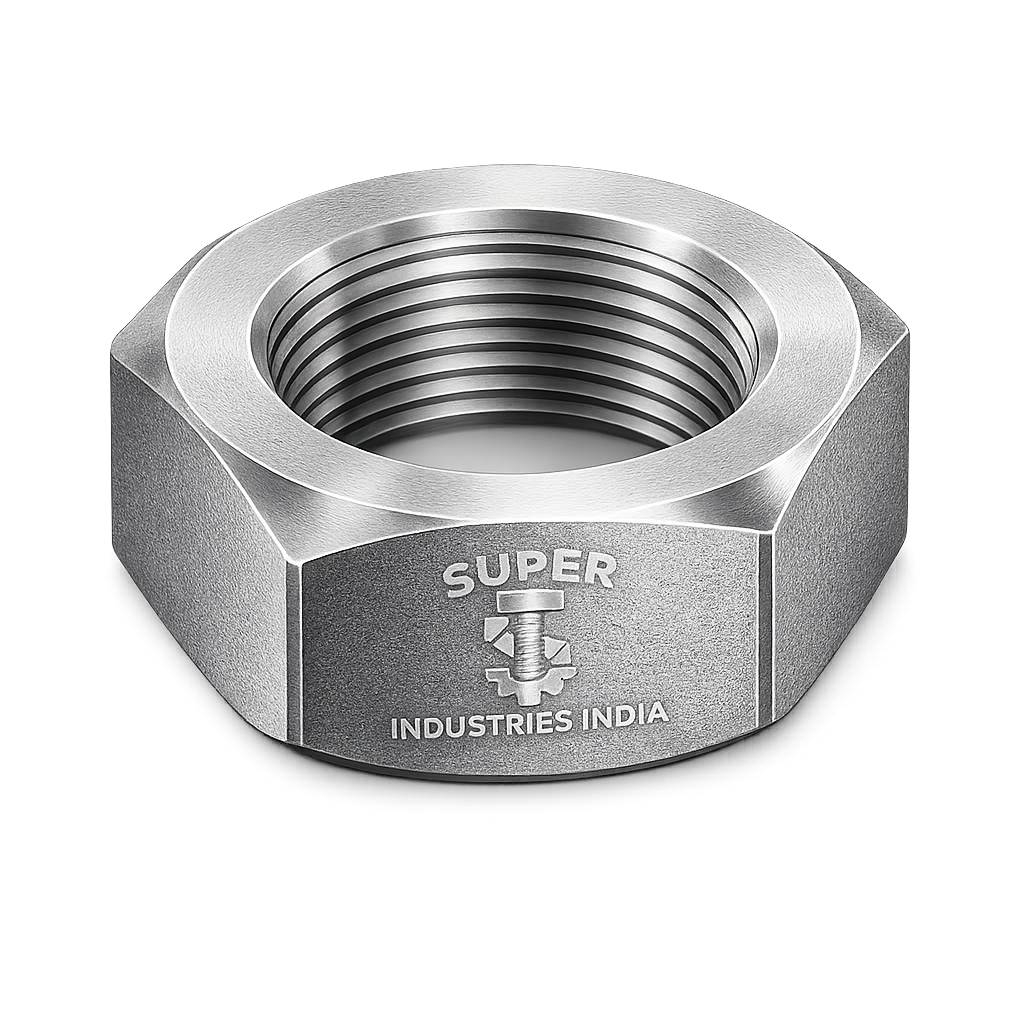
Role in Bolted Joint Systems
Jam Nut Locking is a mechanical locking method used to stabilize threaded fastener assemblies where resistance to loosening under dynamic loading is required. It is widely implemented in engineered joints where preload retention and positional locking are critical to system integrity.
In a standard bolted joint, a single nut is tightened to generate preload. However, under cyclic loads, thermal expansion, and vibration, this preload may reduce due to:
- Embedment relaxation
- Micro-slip at thread interfaces
- Transverse vibration (Junker effect)
- Differential thermal expansion
The double nut locking method—specifically Jam Nut Locking—introduces a secondary nut to create a controlled interference condition within the thread system, improving resistance to self-loosening.
Applications Across Industries
Jam Nut Locking is applied in:
Oil & Gas
- Flange joints in piping systems
- Valve locking assemblies
- Equipment supports under vibration
Power Generation
- Turbine auxiliary systems
- Boiler structural joints
- Rotating equipment supports
Heavy Machinery
- Gear assemblies
- Bearing retention systems
- Shaft positioning
Railways
- Track fasteners
- Suspension systems
- Coupling mechanisms
Infrastructure & Structural Systems
- Steel frame connections
- Bridge components
- Anchor bolt assemblies
Process Industries
- Pump and compressor assemblies
- Agitator shafts
- Chemical processing equipment
Why Jam Nuts Are Used Alongside Standard Nuts
A single nut relies on friction between mating threads and bearing surfaces. Under dynamic conditions, this friction can be overcome, leading to rotation and loosening.
Jam Nut Locking introduces:
- Opposing thread forces
- Increased contact pressure
- Reduced relative motion between threads
This results in:
- Higher resistance to loosening
- Improved preload stability
- Reduced maintenance frequency
Limitations of Single-Nut Fastening
| Parameter | Single Nut System | Jam Nut Locking System |
|---|---|---|
| Vibration Resistance | Limited | Enhanced |
| Preload Retention | Moderate | High |
| Loosening Risk | High under dynamic load | Reduced |
| Redundancy | None | Secondary locking element |
Comparison with Alternative Locking Systems
| Locking Method | Mechanism | Limitations |
|---|---|---|
| Lock Washers | Spring force | Loss of effectiveness under high load |
| Nyloc Nuts | Polymer insert friction | Temperature limitations |
| Chemical Locking | Adhesive bonding | Requires curing, not reusable |
| Jam Nut Locking | Thread interference | Requires correct installation |
Jam Nut Locking is preferred in high-temperature and heavy-duty applications where polymer or chemical methods are unsuitable.
2. Technical Definition of Jam Nut Locking
Formal Definition
Jam Nut Locking is a mechanical locking technique in which a secondary nut (typically thinner) is tightened against a primary nut to create thread interference, restricting rotational movement and stabilizing preload.
Core Functional Elements
- Primary Nut: Provides main preload
- Jam Nut: Secondary locking element
- Thread Interface: Zone of induced interference
- Bolt/Stud: Load-carrying member
Mechanism Classification
Jam Nut Locking functions as:
- Thread interference-based locking system
- Preload stabilization method
- Axial displacement restriction mechanism
Thin Nut vs Full Nut Interaction
| Parameter | Jam Nut (Thin Nut) | Standard Nut |
|---|---|---|
| Thickness | Reduced | Full height |
| Function | Locking | Load bearing |
| Thread Engagement | Partial | Full |
| Position | Top or bottom | Primary location |
The reduced thickness of the jam nut allows controlled deformation and localized stress concentration during reverse tightening.
Top Jam vs Bottom Jam Configuration
Top Jam Method (Preferred)
- Tighten primary nut to required torque
- Tighten jam nut against primary nut
Advantages:
- Better load distribution
- More stable locking condition
Bottom Jam Method
- Install jam nut first
- Tighten primary nut against it
Limitations:
- Less effective locking
- Reduced preload control
Thread Class Compatibility
Proper locking performance depends on thread class fit:
| Thread Class | Fit Type | Application |
|---|---|---|
| 2A / 2B | Standard fit | General industrial use |
| 3A / 3B | Tight tolerance | Precision assemblies |
Tighter classes improve:
- Contact surface area
- Frictional resistance
- Locking reliability
3. Engineering & Locking Principle
Thread Friction Mechanics
In a threaded assembly:
- Torque applied → generates axial preload
- Friction occurs at:
- Thread flanks
- Nut bearing surface
In Jam Nut Locking:
- Secondary tightening alters force distribution
- Creates opposing frictional forces
Load Redistribution Between Nuts
When the jam nut is tightened:
- Load is partially transferred from primary nut
- Contact pressure increases between threads
- Relative motion between threads is restricted
This results in:
- Increased frictional resistance
- Reduced loosening tendency
Elastic Deformation in Threads
During locking:
- Threads undergo elastic deformation
- Localized stress develops at contact points
- Slight distortion increases friction coefficient
This deformation is controlled and reversible within material limits.
Contact Pressure Increase
Reverse tightening of the jam nut:
- Forces threads into tighter engagement
- Increases normal force between mating surfaces
- Enhances frictional locking
Reverse Tightening Mechanism
The key principle:
- Primary nut applies preload
- Jam nut applies reverse axial force
This creates:
- Opposing stress fields
- Locking condition due to thread binding
Friction Coefficient Influence
Torque–preload relationship:
- Higher friction → lower preload for same torque
- Lower friction → higher preload
In Jam Nut Locking:
- Controlled friction increase improves locking
- Excess friction may reduce preload accuracy
Torque Interaction Between Nuts
Torque applied to jam nut affects:
- Residual preload in primary nut
- Contact pressure at thread interface
Proper sequence ensures:
- Primary preload is maintained
- Locking is effective
Self-Loosening Prevention Under Vibration
Under transverse vibration:
- Micro-slips occur at thread interface
- Single nut may rotate
Jam Nut Locking prevents this by:
- Increasing frictional threshold
- Eliminating free rotational clearance
- Creating opposing force system
Fundamental Locking Behavior Summary
| Parameter | Effect in Jam Nut Locking |
|---|---|
| Friction | Increased |
| Thread Movement | Restricted |
| Preload Stability | Improved |
| Vibration Resistance | Enhanced |
| Rotation Freedom | Eliminated |
4. Applicable Standards for Jam Nut Locking
The performance of Jam Nut Locking systems is governed by dimensional, material, and mechanical standards. Selection must align with load conditions, temperature range, and inspection requirements defined in EPC specifications.
Dimensional Standards
ASME B18.2.2
Covers:
- Inch-series hex nuts (including thin nuts)
- Across flats dimensions
- Thickness tolerances
- Thread engagement requirements
Application:
- Oil & Gas (US-based projects)
- Power and EPC contracts following ASME systems
DIN 439 (Jam Nuts)
Primary standard for:
- Thin hex nuts (jam nuts)
- Reduced thickness configuration
- Metric sizing
Application:
- European projects
- Structural and mechanical assemblies
ISO 4035 / ISO 8675
- ISO 4035 → Hex thin nuts (standard pitch)
- ISO 8675 → Fine thread thin nuts
Application:
- Global metric projects
- Precision assemblies
Material Standards
ASTM A194
Covers:
- Carbon and alloy steel nuts
- High-temperature service
- Pressure-containing applications
Common Grades:
- Gr 2H → Alloy steel, high strength
- Gr 8 / 8M → Stainless steel
ASTM A563
Covers:
- Carbon steel nuts
- Structural and general-purpose applications
Common Grades:
- Gr A → Low strength
- Gr DH → Medium-high strength (quenched & tempered)
Standard Mapping to Service Conditions
| Standard | Type | Typical Use | Temperature Range | Load Category |
|---|---|---|---|---|
| ASME B18.2.2 | Dimensional | Inch fasteners | Ambient to high | Medium–High |
| DIN 439 | Dimensional | Metric jam nuts | Ambient | Medium |
| ISO 4035 / 8675 | Dimensional | Precision metric | Ambient–moderate | Medium |
| ASTM A194 | Material | Pressure systems | High temperature | High |
| ASTM A563 | Material | Structural | Ambient | Medium |
Engineering Relevance
Selection of standard affects:
- Thread engagement efficiency
- Preload distribution
- Locking reliability in Jam Nut Locking assemblies
- Inspection compliance during third-party audits
5. Material & Grade Options
Material selection directly influences:
- Strength
- Corrosion resistance
- Temperature capability
- Long-term preload retention
Carbon Steel
ASTM A563 Grade A / DH
- Moderate strength (Gr A)
- Higher strength with heat treatment (Gr DH)
- Used in structural and general bolting
Characteristics:
- Good machinability
- Moderate corrosion resistance (requires coating)
- Suitable for ambient conditions
Alloy Steel
ASTM A194 Grade 2H
- Quenched and tempered
- High strength and hardness
- Suitable for high-pressure and high-temperature systems
Applications:
- Flanged joints
- Pressure vessels
- Oil & gas bolting systems
Stainless Steel
ASTM A194 Grade 8 / 8M
- Austenitic stainless steel
- Excellent corrosion resistance
- Non-magnetic (in annealed condition)
Applications:
- Marine environments
- Chemical processing
- Hygienic systems
Limitations:
- Lower yield strength compared to alloy steel
- Galling risk during tightening
Duplex & Special Alloys (Project-Specific)
Used where:
- Chloride stress corrosion is critical
- High strength + corrosion resistance required
Examples:
- Duplex stainless steels
- Nickel-based alloys
MANDATORY: Material Comparison Table
| Grade | Yield Strength (MPa) | Tensile Strength (MPa) | Temperature Range | Corrosion Resistance | Typical Industry Use |
|---|---|---|---|---|---|
| ASTM A563 Gr A | ~250 | ~400–550 | Ambient | Low | Structural, infrastructure |
| ASTM A563 Gr DH | ~450 | ~700–900 | Moderate | Low–Moderate | Heavy structural joints |
| ASTM A194 Gr 2H | ~650 | ~850–1000 | High | Moderate | Oil & gas, pressure systems |
| ASTM A194 Gr 8 | ~205 | ~515–720 | Moderate | High | Chemical, marine |
| ASTM A194 Gr 8M | ~205 | ~515–720 | Moderate | Very High | Offshore, corrosive environments |
Engineering Considerations
Material selection must consider:
- Bolt–nut compatibility
- Strength hierarchy (nut ≥ bolt requirement)
- Thermal expansion compatibility
- Risk of galling (especially in stainless steel Jam Nut Locking systems)
6. Heat Treatment Information
Heat treatment controls:
- Mechanical strength
- Hardness
- Toughness
- Resistance to deformation under load
Quenching & Tempering
Applicable to:
- ASTM A194 Gr 2H
- ASTM A563 Gr DH
Process:
- Heating above transformation temperature
- Rapid cooling (quenching)
- Controlled reheating (tempering)
Results:
- High strength
- Controlled hardness
- Improved toughness
Normalizing
Used for:
- Carbon steel nuts
Process:
- Heating followed by air cooling
Results:
- Uniform grain structure
- Improved machinability
- Moderate strength
Stress Relieving
Purpose:
- Remove residual stresses from machining or forming
Application:
- Precision fasteners
- Large-size nuts
Hardness Ranges (Typical)
| Grade | Hardness (HB / HRC) |
|---|---|
| A563 Gr A | 120–180 HB |
| A563 Gr DH | 187–302 HB |
| A194 Gr 2H | 248–352 HB |
| A194 Gr 8 / 8M | 140–223 HB |
Microstructure Behavior
- Quenched & tempered → tempered martensite
- Normalized → ferrite-pearlite
- Stainless → austenitic structure
Microstructure affects:
- Fatigue resistance
- Thread wear
- Long-term locking performance
Impact Testing Relevance
For low-temperature applications:
- Charpy V-notch testing required
- Ensures resistance to brittle fracture
7. Manufacturing Process for Jam Nut Locking Components
Manufacturing must ensure:
- Dimensional precision
- Thread accuracy
- Mechanical integrity
- Traceability
Step 1 — Raw Material Inspection
- Chemical composition verification
- Mill test certificate validation
- Visual and dimensional checks
Step 2 — Forging / Forming
Hot Forging
- Used for large sizes
- Improves grain flow
- Enhances mechanical strength
Cold Forming
- Used for smaller sizes
- Better surface finish
- High dimensional accuracy
Step 3 — Thread Cutting / Rolling
Thread Cutting
- Machining process
- Suitable for large diameters
Thread Rolling
- Cold working process
- Improves fatigue strength
- Better surface finish
Step 4 — Heat Treatment
As per material grade:
- Quenching & tempering
- Normalizing
Ensures:
- Required strength class
- Hardness compliance
Step 5 — Surface Finishing
Applied based on service condition:
- Corrosion protection
- Friction control
- Identification
(Details in Section 10)
Step 6 — Inspection
- Thread gauge verification
- Dimensional checks
- Mechanical testing
Step 7 — Marking & Traceability
Includes:
- Grade marking
- Heat number
- Manufacturer identification
Ensures:
- Full traceability
- Compliance with EPC documentation
Step 8 — Packaging
- Segregation by heat and batch
- Protection against corrosion and damage
- Export-compliant packing
Surface Finish Options & Functional Impact
Surface finish affects:
- Corrosion resistance
- Friction coefficient
- Torque–tension relationship in Jam Nut Locking
Common Surface Finishes
Zinc Plating
- Electroplated coating
- Moderate corrosion resistance
Hot-Dip Galvanizing (HDG)
- Thick zinc coating
- High corrosion resistance
Consideration:
- Requires oversize threading
Black Oxide
- Minimal corrosion protection
- Maintains dimensional accuracy
Phosphate Coating
- Improves lubrication
- Reduces friction variability
PTFE Coating
- Low friction coefficient
- Improves torque consistency
Passivation (Stainless Steel)
- Enhances corrosion resistance
- Removes free iron contamination
Friction Coefficient Impact
| Surface Finish | Friction Coefficient (Approx.) | Effect on Locking |
|---|---|---|
| Dry (uncoated) | 0.18–0.25 | Higher torque required |
| Zinc plated | 0.12–0.18 | Moderate friction |
| PTFE coated | 0.05–0.10 | Low friction, higher preload |
| Phosphate + oil | 0.10–0.15 | Controlled tightening |
Coating vs Torque Relationship
Lower friction:
- Increases preload for same torque
- Requires torque adjustment
Higher friction:
- Reduces preload
- May improve locking but reduce accuracy
Proper torque specification is essential in Jam Nut Locking assemblies.
A. Dimensional Table — Jam Nut vs Standard Nut
Dimensional relationships directly influence thread engagement, load transfer, and locking efficiency in Jam Nut Locking assemblies.
| Thread Size | Pitch (mm) | Jam Nut Thickness (mm) | Standard Nut Thickness (mm) | Across Flats (mm) |
|---|---|---|---|---|
| M6 | 1.0 | 3.2 | 5.0 | 10 |
| M8 | 1.25 | 4.0 | 6.5 | 13 |
| M10 | 1.5 | 5.0 | 8.0 | 17 |
| M12 | 1.75 | 6.0 | 10.0 | 19 |
| M16 | 2.0 | 8.0 | 13.0 | 24 |
| M20 | 2.5 | 10.0 | 16.0 | 30 |
| M24 | 3.0 | 12.0 | 19.0 | 36 |
| M30 | 3.5 | 15.0 | 24.0 | 46 |
Engineering Observations
- Jam nut thickness ≈ 0.5 × standard nut
- Reduced thickness enables controlled elastic deformation
- Sufficient thread engagement must still be maintained (minimum 1D total engagement recommended)
- Across flats dimension remains identical for wrench compatibility
B. Torque Chart (MANDATORY)
Torque values must consider:
- Material strength class
- Surface condition (dry vs lubricated)
- Friction coefficient
Metric Bolt Torque Values (Indicative)
| Bolt Size | Property Class | Dry Torque (Nm) | Lubricated Torque (Nm) |
|---|---|---|---|
| M8 | 8.8 | 25 | 18 |
| M10 | 8.8 | 50 | 35 |
| M12 | 8.8 | 85 | 60 |
| M16 | 8.8 | 210 | 150 |
| M20 | 8.8 | 410 | 290 |
| M12 | 10.9 | 120 | 85 |
| M16 | 10.9 | 300 | 210 |
| M20 | 10.9 | 580 | 410 |
| M24 | 10.9 | 1000 | 700 |
ASTM Equivalent (Reference)
| Bolt Grade | Equivalent Class | Application |
|---|---|---|
| ASTM A307 | ~4.6 | Light structural |
| ASTM A325 | ~8.8 | Structural |
| ASTM A490 / B7 | ~10.9 | High strength / pressure systems |
Torque Application in Jam Nut Locking
- Apply full torque to primary nut
- Apply secondary torque to jam nut (typically 25–50% of primary torque)
- Ensure no rotation of primary nut during jam tightening
Engineering Note
Incorrect torque sequence may:
- Reduce preload
- Introduce uneven load distribution
- Reduce locking effectiveness
C. Preload Calculation Guide (MANDATORY)
Preload is the primary factor governing joint integrity.
Torque–Tension Relationship
![\[F = \frac{T}{K \cdot d}\]](https://superindustriesindia.in/wp-content/ql-cache/quicklatex.com-047c3812ff26cb229181955bd579e870_l3.png "Rendered by QuickLaTeX.com")
Where:
- F = Preload force (N)
- T = Applied torque (Nm)
- K = Nut factor (friction coefficient, typically 0.15–0.25)
- d = Nominal bolt diameter (m)
Clamp Force Logic
- Torque generates preload
- Preload creates clamping force
- Clamping force resists external loads
Jam Nut Locking ensures:
- Preload retention over time
- Reduced loss due to vibration
Sample Calculation
Given:
- Bolt size = M16 (d = 0.016 m)
- Torque = 210 Nm
- Nut factor (K) = 0.2
Calculation:
![\[F = \frac{210}{0.2 \times 0.016} = 65{,}625 \, \text{N}\]](https://superindustriesindia.in/wp-content/ql-cache/quicklatex.com-ddbae510c0fe7c6e9687e893cff81ca4_l3.png "Rendered by QuickLaTeX.com")
Interpretation
- Clamp force ≈ 65.6 kN
- Jam nut must not reduce this preload during locking
- Proper tightening sequence ensures preload stability
Preload Considerations in Jam Nut Locking
- Excess torque on jam nut may reduce preload
- Controlled torque ensures locking without preload loss
- Lubrication affects K factor and preload accuracy
D. Locking Efficiency Explanation
Locking efficiency is defined as the system’s ability to resist self-loosening under dynamic conditions.
Mechanism of Efficiency Improvement
Jam Nut Locking improves efficiency by:
- Increasing thread friction
- Eliminating axial clearance
- Creating opposing force interaction
Effect Under Vibration
| Condition | Single Nut | Jam Nut Locking |
|---|---|---|
| Transverse vibration | High loosening probability | Reduced |
| Micro-slip | Frequent | Restricted |
| Preload loss | Progressive | Controlled |
Comparison with Other Locking Systems
| Method | Efficiency | Limitations |
|---|---|---|
| Lock washer | Low | Flattening under load |
| Nyloc nut | Moderate | Temperature limits |
| Chemical locking | High | Non-reusable |
| Jam Nut Locking | High (mechanical) | Installation dependent |
Engineering Conclusion
Jam Nut Locking provides:
- Predictable locking behavior
- Reusable mechanical system
- Suitability for high-temperature environments
E. Mechanical Property Table
Mechanical properties must align with bolt grade to avoid thread stripping or failure.
| Property | ASTM A563 Gr DH | ASTM A194 Gr 2H | ASTM A194 Gr 8 |
|---|---|---|---|
| Yield Strength (MPa) | ~450 | ~650 | ~205 |
| Tensile Strength (MPa) | 700–900 | 850–1000 | 515–720 |
| Hardness | 187–302 HB | 248–352 HB | 140–223 HB |
| Elongation (%) | 12–18 | 10–15 | 30–40 |
Engineering Observations
- Alloy steel (2H) suitable for high-load applications
- Stainless steel offers ductility but lower strength
- Nut grade must match or exceed bolt requirement
F. Corrosion Resistance Table
Material performance varies significantly based on environment.
| Environment | Carbon Steel | Alloy Steel | Stainless Steel |
|---|---|---|---|
| Marine | Poor | Poor–Moderate | Excellent |
| Chemical | Poor | Moderate | Excellent |
| High Humidity | Moderate (coated) | Moderate | High |
| Industrial | Moderate | High | High |
Engineering Implications
- Coatings required for carbon steel in corrosive environments
- Stainless preferred where corrosion dominates over strength
- Duplex alloys used in aggressive chloride environments
8. Inspection & Quality Control Methods
Inspection ensures compliance with:
- Dimensional standards
- Mechanical properties
- Material traceability
Thread Gauge Inspection
- GO / NO-GO gauges
- Ensures thread class compliance (2B / 3B)
- Critical for Jam Nut Locking performance
Hardness Testing
Methods:
- Brinell (HB)
- Rockwell (HRC)
Purpose:
- Verify heat treatment
- Ensure mechanical strength
Positive Material Identification (PMI)
- Spectrographic analysis
- Confirms alloy composition
Required for:
- Oil & gas projects
- Critical service environments
Magnetic Particle Inspection (MPI)
- Detects surface/subsurface cracks
- Applicable for ferromagnetic materials
Dye Penetrant Inspection (DPI)
- Detects surface defects
- Used for stainless steel and non-magnetic materials
Dimensional Verification
Includes:
- Thickness measurement
- Across flats tolerance
- Thread pitch verification
Third-Party Inspection (TPI)
Conducted by:
- Independent inspection agencies
Scope:
- Witness testing
- Document verification
- Batch approval
Certification
| Certificate Type | Description |
|---|---|
| EN 10204 3.1 | Manufacturer test certificate |
| EN 10204 3.2 | Third-party verified certificate |
Traceability Requirements
Each batch must include:
- Heat number
- Material grade
- Manufacturing lot
- Inspection records
9. Industries Served — Application Mapping for Jam Nut Locking
Jam Nut Locking is implemented across sectors where bolted joints are subjected to vibration, cyclic loading, thermal variation, or positional stability requirements. Selection is typically driven by joint criticality classification within EPC specifications.
Oil & Gas (Upstream, Midstream, Downstream)
Application Areas:
- Flanged joints in piping systems
- Valve gland and actuator locking
- Compressor and pump assemblies
- Structural supports for process equipment
Engineering Requirement:
- High preload retention under vibration
- Resistance to thermal cycling
- Compatibility with ASTM A194 materials
Relevance of Jam Nut Locking:
- Provides mechanical locking without polymer inserts
- Suitable for high-temperature hydrocarbon service
- Maintains joint stability during pressure fluctuations
Power Generation (Thermal, Nuclear, Renewable)
Application Areas:
- Turbine auxiliary systems
- Boiler support structures
- Generator base frames
- Rotating equipment anchoring
Engineering Requirement:
- Fatigue resistance under cyclic loading
- Stability under continuous vibration
- Controlled preload over long service intervals
Use Case:
Jam Nut Locking ensures that fasteners in rotating and vibrating assemblies maintain positional accuracy and clamp force over extended operating cycles.
Heavy Engineering & Industrial Machinery
Application Areas:
- Gearbox assemblies
- Shaft locking systems
- Bearing retention
- Heavy equipment structural joints
Engineering Requirement:
- Resistance to shock loads
- High mechanical strength
- Reusability during maintenance
Railways & Transportation Infrastructure
Application Areas:
- Bogie assemblies
- Track fastening systems
- Coupling mechanisms
- Suspension components
Engineering Requirement:
- Resistance to continuous vibration and impact
- Prevention of loosening under dynamic loading
Infrastructure & Structural Steel Systems
Application Areas:
- Bridge components
- Anchor bolt systems
- Structural connections in steel frameworks
Engineering Requirement:
- Long-term preload retention
- Environmental durability
- Compliance with structural codes
Process & Chemical Industries
Application Areas:
- Agitators and mixers
- Pump assemblies
- Reactor supports
Engineering Requirement:
- Corrosion resistance
- Stability under rotating loads
- Compatibility with stainless steel systems
10. Export Capability & Global Supply Structure
Super Industries operates as a manufacturer and exporter aligned with EPC procurement frameworks and international inspection protocols.
Regions Served
- United States — ASME / ASTM-based projects
- European Union — DIN / ISO compliance
- Middle East — Oil & gas and infrastructure projects
- Southeast Asia — Power and industrial expansion projects
Product Compliance for Export
- ASTM / ASME / DIN / ISO standards
- Project-specific specifications (EPC, OEM)
- Third-party inspection readiness
Packaging Standards
Export packaging is designed to preserve:
- Thread integrity
- Surface coating condition
- Traceability
Typical methods:
- Batch-wise packaging
- Corrosion protection (VCI / oil coating)
- Wooden crates / palletized loads
- Identification labeling with heat number and grade
Documentation Package
Supplied documentation typically includes:
- Mill Test Certificates (MTC)
- EN 10204 3.1 / 3.2 certification
- Inspection reports
- Heat treatment records
- Dimensional inspection reports
- PMI reports (if required)
Logistics Capability
- Containerized shipments (FCL / LCL)
- Break-bulk for large fasteners
- Coordination with EPC logistics schedules
- Export compliance with international trade requirements
11. Procurement & Installation View — Engineering Practice
Correct Installation Sequence (Critical)
Proper installation is essential for effective Jam Nut Locking performance.
Step 1 — Assembly Preparation
- Ensure clean threads (no debris or damage)
- Apply lubrication if specified
- Verify compatibility of nut and bolt grades
Step 2 — Primary Nut Tightening
- Tighten primary nut to specified torque
- Achieve required preload
Step 3 — Jam Nut Installation
- Thread jam nut onto bolt
- Bring into contact with primary nut
Step 4 — Secondary Tightening
- Tighten jam nut against primary nut
- Apply controlled torque (typically 25–50% of primary torque)
- Prevent rotation of primary nut during this step
Step 5 — Final Verification
- Confirm no rotation of primary nut
- Verify torque application
- Inspect alignment and seating
Torque Application Logic
| Step | Component | Torque Level | Purpose |
|---|---|---|---|
| 1 | Primary Nut | 100% | Generate preload |
| 2 | Jam Nut | 25–50% | Create locking interference |
Field Inspection Practices
- Visual inspection of seating surfaces
- Torque re-check (if specified)
- Verification of thread engagement
- Inspection of coating condition
Reuse Limitations
Jam nuts may be reused under controlled conditions:
- No thread damage
- No plastic deformation
- Coating integrity maintained
Not recommended for:
- Critical joints with high safety classification
- High-temperature service after prolonged exposure
Storage Conditions
- Dry, controlled environment
- Protection from moisture and contaminants
- Segregation by grade and heat number
- Preservation of coating integrity
12. Custom Engineering Capabilities
Super Industries supports project-specific requirements for Jam Nut Locking systems.
Custom Thread Configurations
- Non-standard metric and inch threads
- Fine pitch threads for precision assemblies
- Tight tolerance classes (3A / 3B equivalent)
Special Thickness Jam Nuts
- Increased thickness for higher engagement
- Reduced thickness for constrained assemblies
High-Strength Custom Grades
- Alloy steel variants beyond standard grades
- Application-specific mechanical properties
Special Surface Coatings
- PTFE-based coatings for controlled friction
- Duplex coatings for corrosion protection
- Project-specified coating systems
Project-Specific Marking
- Heat number stamping
- Client-specific identification
- Traceability coding aligned with EPC requirements
13. Engineering Conclusion — Jam Nut Locking
Jam Nut Locking is a mechanically reliable method for improving the stability of threaded fastener assemblies in demanding service conditions.
Performance Summary
| Parameter | Performance Outcome |
|---|---|
| Preload Retention | Improved |
| Vibration Resistance | High |
| Reusability | Conditional |
| Temperature Capability | High (material dependent) |
| Installation Sensitivity | High (procedure critical) |
Engineering Assessment
From a joint integrity perspective:
- Provides a friction-based mechanical locking mechanism
- Eliminates reliance on temperature-sensitive components
- Enhances resistance to self-loosening under vibration
- Maintains compatibility with standard fastener systems
Consultant Evaluation Criteria Alignment
Jam Nut Locking systems manufactured by Super Industries align with:
- ASME bolting and joint integrity principles
- ASTM / DIN / ISO material and dimensional standards
- EPC procurement and inspection requirements
- Third-party verification protocols
Final Technical Position
For applications requiring:
- Controlled preload
- Resistance to vibration-induced loosening
- High-temperature operability
- Mechanical reusability