
L BOLTS
Super Industries “Global Manufacturer of Heavy & Custom Engineered Fasteners for Oil & Gas, Power & EPC Contractors.”
Super Industries operates as a manufacturer and global exporter of L Bolts used for structural anchoring systems in heavy infrastructure, energy, and industrial projects.
The products are manufactured to comply with internationally recognized mechanical fastener standards and are intended for use in steel-to-concrete structural connections where permanent anchorage and load transfer are required.
1. Industry Context & Structural Relevance
In heavy industrial construction and infrastructure engineering, structural anchoring systems are essential for transferring loads from steel structures into reinforced concrete foundations.
Among the various anchoring solutions used in civil and industrial engineering, L Bolts represent one of the most widely applied embedded anchor bolt configurations due to their mechanical anchorage characteristics and installation reliability.
These anchor fasteners are used to secure structural components such as:
• Steel columns and base plates
• Power plant turbine foundations
• Transmission tower bases
• Bridge structural members
• Industrial equipment foundations
• Petrochemical processing structures
• Steel support frames for heavy machinery
• Cement plant equipment bases
• Offshore structural modules
The structural purpose of L Bolts is to create a mechanical interface between steel structures and concrete foundations, ensuring that structural loads are safely transferred into the foundation system without loss of stability.
Structural Role in Foundation Systems
In a typical structural assembly:
- Reinforced concrete foundation is cast.
- L Bolts are embedded within the concrete during pouring.
- Steel base plates are installed over the exposed threaded portion.
- Nuts and washers clamp the steel structure to the concrete base.
Through this configuration, the anchor system must resist several forces:
• Tensile uplift forces
• Lateral shear forces
• Combined bending and tension loads
• Dynamic equipment vibration loads
• Seismic structural forces
The embedded geometry of the bolt ensures that the anchor fastener becomes integrally locked within the concrete matrix, enabling reliable load transfer throughout the structural life of the installation.
Why Bent Anchor Bolts Are Used Instead of Straight Anchors
Straight anchor rods can rely only on bond friction between the steel surface and concrete. Under high tensile loads, this bond may fail through slip or pull-out.
Bent anchor bolts such as L Bolts introduce mechanical anchorage, which significantly improves pull-out resistance.
The L-shaped bend forms a physical bearing point inside the concrete, creating a mechanical interlock between the anchor and the concrete foundation.
This geometry provides several engineering advantages:
1. Mechanical Anchorage
The bent leg of the bolt acts as a hook embedded within the concrete mass, preventing direct withdrawal under tensile loads.
2. Improved Pull-Out Resistance
The concrete must fail structurally for the bolt to be extracted. This significantly increases resistance compared with friction-based anchors.
3. Load Distribution
The hooked section distributes forces over a larger concrete volume rather than concentrating load at the surface interface.
4. Structural Reliability
Because the anchorage relies on physical geometry rather than adhesive bonding, the system remains stable even under:
• temperature variation
• moisture exposure
• vibration environments
These characteristics make L Bolts suitable for long-life infrastructure and industrial equipment installations.
2. Technical Definition of L Bolts
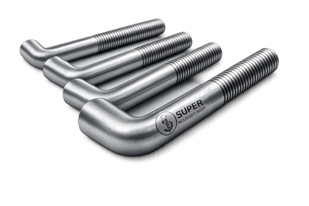
L Bolts are bent anchor fasteners designed to embed into concrete foundations and secure structural steel components through threaded clamping connections.
They are classified as embedded structural anchoring systems used in permanent construction.
An L Bolt consists of three primary sections:
- Threaded section — located above the concrete surface
- Straight shank section — passing through the embedment zone
- Bent anchoring section (L-bend) — forming the mechanical anchorage within concrete
The fastener is installed during foundation casting and becomes permanently embedded within the concrete structure.
Geometry of L Bolts
The structural geometry of L Bolts directly influences their load-bearing performance.
L-Shape Bend
The defining feature of L Bolts is the 90-degree bend at the lower end of the bolt.
This bend forms the mechanical anchorage within the concrete.
Threaded End
The upper portion of the bolt is threaded to accept:
• Heavy hex nuts
• Structural washers
• Base plate clamping systems
Threads typically follow international standards such as:
• UNC / UNF threads
• Metric ISO threads
Embedment Length
Embedment length refers to the depth of the bolt inside the concrete foundation.
Greater embedment depth generally increases resistance against:
• pull-out failure
• concrete breakout failure
Hooked Anchoring Section
The horizontal leg of the bolt acts as the load-bearing anchor element, transferring tension forces into the surrounding concrete mass.
Common Variants of L Bolts
Although the fundamental geometry remains similar, several variants are commonly used depending on project requirements.
Standard L Anchor Bolts
Used for structural base plate anchoring in civil and industrial construction.
Typical applications:
• structural steel columns
• equipment foundations
• small to medium load structures
Long Anchor L Bolts
Designed with extended embedment lengths for:
• high uplift forces
• large concrete foundations
• heavy equipment anchoring
These are common in:
• power plants
• turbine foundations
• petrochemical plants
Foundation Anchor Bolts
Used for large industrial structures where bolt diameters and embedment depths are significant.
Applications include:
• refinery equipment structures
• heavy rotating machinery
• large steel towers
Heavy Equipment Anchor Bolts
These bolts are manufactured with large diameters and extended hook sections to resist high dynamic loads.
Typical industries include:
• cement manufacturing
• steel plants
• mining facilities
• industrial processing units
3. Structural Load Transfer Principle
The structural performance of L Bolts depends on how loads are transferred from the steel structure into the surrounding concrete.
Load transfer mechanisms typically involve three primary interactions:
• Bolt steel strength
• Concrete compressive strength
• Mechanical anchorage created by the L-bend
The anchor system must be designed to resist several potential failure modes.
Tensile Load Transfer
Tensile forces occur when structural loads attempt to lift the steel base plate away from the foundation.
Examples include:
• wind uplift loads
• seismic forces
• equipment vibration
• thermal expansion forces
Under tensile loading, the bolt shank experiences axial stress.
The relationship between applied load and stress in the bolt is defined by the standard engineering equation:
![\[\sigma = \frac{F}{A}\]](https://superindustriesindia.in/wp-content/ql-cache/quicklatex.com-d820ba2a7649df33c4e35cab55485169_l3.png "Rendered by QuickLaTeX.com")
Where:
σ = tensile stress in the bolt
F = applied tensile force
A = tensile stress area of the bolt
If the tensile stress exceeds the bolt material strength, steel failure occurs.
Shear Load Transfer
Shear loads act parallel to the concrete surface, typically generated by:
• lateral structural movement
• machinery vibration
• horizontal wind loads
• structural misalignment forces
In shear loading conditions:
• the bolt shank resists the lateral force
• friction between base plate and concrete may contribute to load transfer
Shear resistance depends primarily on:
• bolt diameter
• bolt material strength
• concrete bearing capacity
Combined Loading Conditions
Most anchor bolts in structural applications experience combined loading, including:
• tensile forces
• shear forces
• bending moments
Structural engineers evaluate combined loading conditions using interaction formulas that ensure neither steel failure nor concrete failure occurs.
Concrete Bond Interaction
In addition to mechanical anchorage, the bolt interacts with concrete through bond forces.
Bond strength depends on:
• concrete strength
• surface condition of the bolt
• embedment depth
• curing conditions
However, bond strength alone is insufficient for high-load structural anchors.
The L-bend geometry provides the primary anchoring mechanism.
Pull-Out Resistance Theory
Pull-out failure occurs when the bolt is extracted from the concrete without breaking the steel.
For L Bolts, pull-out resistance is determined by:
• embedment depth
• hook length
• concrete compressive strength
• surrounding reinforcement
The mechanical hook forces the concrete to resist the load through bearing and compression forces within the concrete matrix.
Concrete Cone Failure Mode
One of the most common structural failure mechanisms for anchor bolts is concrete cone failure.
In this failure mode:
• the bolt remains intact
• a cone-shaped portion of concrete fractures and lifts out of the foundation
The size of the cone depends on:
• embedment depth
• edge distance
• anchor spacing
Proper anchor design ensures the concrete breakout capacity exceeds the applied loads.
Anchor Steel Failure Mode
Steel failure occurs when the tensile stress in the bolt exceeds the ultimate tensile strength of the material.
This failure mode is typically controlled through:
• proper material grade selection
• bolt diameter sizing
• adequate safety factors
Structural design aims to ensure that steel failure does not occur before concrete failure limits are reached.
Influence of Embedment Depth on Load Capacity
Embedment depth is one of the most critical parameters in anchor bolt design.
Increasing embedment depth provides several structural advantages:
• increased pull-out resistance
• larger concrete breakout cone
• improved load distribution within the foundation
However, embedment depth must also consider:
• foundation thickness
• reinforcement placement
• construction practicality
Structural engineers often specify embedment depths ranging from:
• 12 × bolt diameter
• up to 20 × bolt diameter for heavy structures
Transition to Structural Design Considerations
The structural principles described above form the basis for anchor bolt engineering design.
In large infrastructure and industrial projects, the design of L Bolts must account for:
• structural loads
• concrete strength
• installation geometry
• international fastener standards
• manufacturing tolerances
Super Industries
Global Manufacturer of Heavy & Custom Engineered Fasteners & Flanges
4. Load Engineering & Structural Design
The design of L Bolts used in structural anchoring systems requires evaluation of multiple load conditions and interaction with the surrounding concrete foundation. Structural engineers must verify that both the steel fastener capacity and the concrete anchorage capacity remain within safe limits under all operational conditions.
Typical structural loads acting on anchor bolts include:
• Tensile loads
• Shear loads
• Combined tension and shear loading
• Dynamic loads from machinery
• Thermal expansion loads
• Seismic forces
The design process must ensure that none of the possible failure mechanisms occur within the operating load envelope.
Tensile Load Considerations
Tensile loads occur when structural forces attempt to lift the connected steel structure away from the concrete foundation.
Sources of tensile loading include:
• Wind uplift on steel structures
• Dynamic vibration from rotating machinery
• Thermal expansion of connected equipment
• Seismic loading in earthquake-prone regions
When subjected to tensile loading, the anchor bolt must resist the applied force without exceeding the allowable tensile stress of the material grade.
Important design parameters include:
• Bolt diameter
• Bolt material grade
• Effective tensile stress area
• Embedment depth
• Concrete compressive strength
Higher grade bolts typically provide greater tensile load capacity, allowing the structural designer to select appropriate bolt sizes for heavy installations.
Shear Load Considerations
Shear forces act parallel to the surface of the concrete foundation and may arise from structural or operational forces.
Common sources of shear loading include:
• Equipment lateral forces
• Structural movement under wind loads
• Thermal displacement of structures
• Seismic horizontal ground motion
Shear resistance in L Bolts is provided primarily by:
• Bolt shank strength
• Bearing interaction between bolt and base plate
• Friction between the base plate and the concrete surface
In some structural systems, shear keys or shear plates are added to reduce the direct shear load acting on anchor bolts.
Combined Loading Conditions
In most structural applications, anchor bolts experience simultaneous tensile and shear loading.
Examples include:
• Transmission towers subjected to wind forces
• Industrial equipment foundations with vibration loads
• Steel building columns under combined vertical and lateral loads
Combined loading is evaluated using interaction equations where the combined stress ratio must remain below the allowable design limit.
The design engineer must confirm that:
• Bolt tensile capacity is adequate
• Bolt shear capacity is sufficient
• Concrete breakout resistance is not exceeded
Anchor Design Safety Factors
Structural anchoring systems are typically designed with conservative safety factors due to the critical role of foundation connections.
Safety factors account for uncertainties such as:
• Material variability
• Construction tolerances
• Installation inaccuracies
• Long-term structural loading
Typical safety factor considerations include:
• Steel strength reduction factors
• Concrete breakout safety margins
• Installation tolerance allowances
EPC project specifications frequently require engineering verification calculations before anchor bolt approval.
Edge Distance Effects
Anchor bolts located close to the edge of a concrete foundation are more susceptible to edge breakout failure.
Edge distance refers to the distance between the anchor bolt centerline and the nearest free edge of the concrete.
Insufficient edge distance may lead to:
• Concrete cracking
• Reduced breakout capacity
• Structural instability
Engineering standards often recommend minimum edge distances of 4 to 6 bolt diameters, depending on the anchor design method used.
Anchor Spacing Effects
When multiple L Bolts are installed in a pattern beneath a base plate, the spacing between anchors influences the load distribution in the concrete.
If anchors are spaced too closely:
• Their concrete breakout cones may overlap
• The effective load capacity of each anchor may reduce
Typical design practice ensures that anchor spacing is sufficient to prevent overlapping concrete failure cones under tensile loading.
Dynamic Loads from Machinery
Heavy industrial equipment generates dynamic forces that may impose cyclic stresses on anchor bolts.
Examples include:
• Gas turbines
• Large pumps
• Compressors
• Rotary kilns
• Crushers
Under cyclic loading conditions, anchor bolts must be designed to resist:
• fatigue stresses
• vibration loosening
• repeated tension cycles
For such applications, higher strength bolt grades and deeper embedment depths are typically specified.
Seismic Loading Environments
In seismic regions, structural anchoring systems must resist earthquake-induced forces.
Seismic loads may produce:
• rapid tension fluctuations
• horizontal shear forces
• combined loading conditions
Structural engineers must ensure that anchor bolt systems comply with applicable seismic design provisions in structural codes.
Important considerations include:
• ductility of bolt materials
• sufficient embedment depth
• adequate anchor spacing
5. Dimensional & Design Logic of L Bolts
The geometry of L Bolts directly influences their structural performance and installation reliability.
Each dimensional parameter must be specified in accordance with engineering design calculations and foundation drawings.
Bolt Diameter
Bolt diameter determines the cross-sectional area of the fastener, which directly influences tensile and shear strength.
Common bolt diameters for structural anchoring applications include:
• M12 to M36 (metric)
• 1/2 inch to 2 inches (imperial)
Large infrastructure and heavy equipment installations may require larger diameter anchor bolts exceeding 2 inches.
Thread Length
Thread length refers to the portion of the bolt that remains exposed above the concrete foundation to allow nut and washer engagement.
Thread length must accommodate:
• base plate thickness
• leveling nut adjustment
• washer thickness
• top clamping nut
Typical design practice provides additional thread allowance to permit installation adjustments.
Overall Bolt Length
The total length of an L Bolt includes:
• threaded section above concrete
• straight embedment section
• bent anchoring section
The overall length must be determined based on foundation thickness and required embedment depth.
Embedment Length
Embedment length represents the vertical depth of the anchor bolt inside the concrete foundation.
This parameter is critical because it affects:
• pull-out resistance
• concrete breakout strength
• load distribution within the concrete mass
Large industrial foundations often require embedment depths between 300 mm and 1500 mm, depending on structural loads.
Hook Length
The hook length refers to the horizontal leg of the L-shaped bend.
This portion of the bolt provides the mechanical anchorage that prevents pull-out.
Longer hook lengths generally provide:
• increased mechanical resistance
• improved anchoring reliability
However, hook length must remain compatible with reinforcement layout inside the concrete foundation.
Bend Radius
The bend radius is the curvature used when forming the L-shape.
Proper bend radius control is important because:
• excessively tight bends may cause material cracking
• large bend radii reduce anchoring efficiency
Manufacturing specifications normally define minimum bend radius based on bolt diameter and material grade.
Dimensional Tolerance Controls
To ensure reliable structural performance, dimensional tolerances must be carefully controlled during manufacturing.
Critical tolerance parameters include:
Thread Tolerances
Thread profiles must conform to applicable standards such as:
• UNC / UNF thread classes
• ISO metric thread standards
Thread tolerances are verified using go / no-go thread gauges.
Straightness Requirements
The shank of the anchor bolt must remain sufficiently straight to ensure:
• proper installation through base plate holes
• uniform load distribution during tightening
Excessive curvature may prevent proper installation or introduce additional stresses.
Bend Angle Precision
The bend angle of L Bolts is normally specified as 90 degrees, with allowable tolerance limits defined by manufacturing standards.
Consistent bend angles ensure that the hook section aligns correctly within the concrete foundation.
Perpendicularity to Base Plates
The exposed threaded portion of the bolt must remain perpendicular to the base plate surface after installation.
Misalignment can cause:
• uneven load distribution
• improper nut seating
• difficulty during equipment installation
Template plates are often used during foundation casting to maintain accurate bolt alignment.
6. Applicable Standards (ASTM / DIN / ISO)
Structural anchor bolts used in infrastructure and industrial projects must comply with internationally recognized fastener material and dimensional standards.
These standards ensure:
• material consistency
• mechanical property control
• compatibility with global engineering specifications
ASTM Standards for Anchor Bolts
ASTM F1554
ASTM F1554 is the primary specification used for structural anchor bolts embedded in concrete foundations.
This standard defines three common grades:
• Grade 36
• Grade 55
• Grade 105
These grades differ in yield strength and tensile capacity, allowing engineers to select the appropriate material strength for specific structural loads.
ASTM A307
ASTM A307 covers carbon steel bolts and studs used for general structural applications.
This specification is sometimes applied in lower-load anchor bolt installations.
ASTM A193 B7
ASTM A193 B7 specifies alloy steel fasteners designed for high strength and high temperature service conditions.
These bolts are commonly used in:
• petrochemical plants
• refinery equipment installations
• high-temperature industrial environments
DIN Standards
DIN 529
DIN 529 defines bent anchor bolts used in structural construction.
The standard specifies:
• bolt geometry
• bend configurations
• dimensional relationships for anchor bolts embedded in concrete
DIN anchor bolts are widely used in European infrastructure projects.
ISO Thread Standards
ISO thread standards define metric thread dimensions and tolerances used in international structural fastener manufacturing.
These standards ensure compatibility between:
• bolts
• nuts
• washers
across global engineering projects.
7. Material & Grade Options
The selection of bolt material is a critical engineering decision that influences:
• structural strength
• temperature performance
• corrosion resistance
• long-term reliability
L Bolts used in infrastructure projects are commonly manufactured from carbon steel, alloy steel, or stainless steel materials.
Carbon Steel Grades
ASTM F1554 Grade 36
This grade provides moderate strength and is commonly used for:
• structural steel columns
• general foundation anchoring
• moderate load infrastructure projects
ASTM F1554 Grade 55
Grade 55 offers higher yield strength than Grade 36 and is widely used in:
• industrial equipment foundations
• heavy structural anchoring
ASTM F1554 Grade 105
This grade provides significantly higher tensile strength and is used in:
• high-load structural anchoring systems
• heavy industrial structures
Alloy Steel Grade
ASTM A193 B7
B7 alloy steel provides:
• high tensile strength
• improved temperature resistance
• suitability for demanding industrial environments
It is commonly used in:
• refineries
• petrochemical plants
• power generation facilities
Stainless Steel Grades
ASTM A193 B8 (SS304)
Provides corrosion resistance suitable for:
• humid environments
• chemical plants
• outdoor infrastructure
ASTM A193 B8M (SS316)
Offers improved corrosion resistance in:
• marine environments
• chloride-exposed structures
Duplex Stainless Steel
Duplex stainless steels are sometimes specified for offshore and highly corrosive environments where both high strength and corrosion resistance are required.
Material Comparison Table
| Grade | Yield Strength | Tensile Strength | Temperature Range | Corrosion Resistance | Typical Structural Use |
|---|---|---|---|---|---|
| ASTM F1554 Gr 36 | ~250 MPa | ~400 MPa | Moderate | Low | Structural columns |
| ASTM F1554 Gr 55 | ~380 MPa | ~520 MPa | Moderate | Low | Equipment foundations |
| ASTM F1554 Gr 105 | ~724 MPa | ~860 MPa | Moderate | Low | High-load structures |
| ASTM A193 B7 | ~720 MPa | ~860 MPa | High temperature service | Moderate | Petrochemical plants |
| ASTM A193 B8 | ~205 MPa | ~515 MPa | Moderate | High | Chemical plants |
| ASTM A193 B8M | ~205 MPa | ~515 MPa | Moderate | Very high | Marine environments |
8. Heat Treatment Information
Certain material grades require controlled heat treatment processes to achieve specified mechanical properties.
Heat treatment affects:
• grain structure
• hardness
• tensile strength
• ductility
Normalizing
Normalizing involves heating the steel above its critical temperature and allowing it to cool in air.
This process improves:
• grain structure uniformity
• toughness
Quenching and Tempering
This heat treatment process involves:
- Heating the steel to high temperature
- Rapid cooling (quenching)
- Controlled reheating (tempering)
Quenching and tempering increases:
• tensile strength
• hardness
• fatigue resistance
Grades such as ASTM A193 B7 typically undergo this treatment.
Stress Relieving
After bending operations, stress relieving may be performed to:
• reduce internal residual stresses
• prevent distortion
This process helps maintain dimensional stability and structural reliability.
Mechanical Property Verification
Heat-treated bolts may undergo testing such as:
• hardness testing
• tensile testing
• Charpy impact testing (for certain project specifications)
These tests confirm compliance with the required mechanical property specifications.
9. Anchor Bolt Dimension Reference Table
The dimensions of L Bolts used in structural anchoring applications are typically determined from structural design calculations and foundation drawings.
Key dimensional parameters include:
• Bolt diameter
• Thread length above foundation
• Embedment depth inside concrete
• Hook length of the bent section
• Total bolt length
These parameters influence load capacity, anchoring reliability, and installation compatibility with structural base plates.
| Bolt Diameter | Thread Length | Embedment Length | Hook Length | Total Length | Recommended Concrete Grade |
|---|---|---|---|---|---|
| M16 (5/8″) | 80 mm | 250 mm | 80 mm | 330 mm | M20 |
| M20 (3/4″) | 90 mm | 300 mm | 100 mm | 390 mm | M20–M25 |
| M24 (1″) | 100 mm | 350 mm | 120 mm | 470 mm | M25 |
| M30 (1-1/4″) | 120 mm | 450 mm | 150 mm | 600 mm | M25–M30 |
| M36 (1-1/2″) | 140 mm | 600 mm | 180 mm | 780 mm | M30 |
| M42 (1-3/4″) | 160 mm | 750 mm | 200 mm | 950 mm | M30–M35 |
| M48 (2″) | 180 mm | 900 mm | 220 mm | 1120 mm | M35 |
Actual dimensions may vary depending on project engineering specifications.
Tensile Load Capacity Table
The tensile capacity of L Bolts is primarily governed by:
• Bolt diameter
• Material grade
• Effective tensile stress area
• Material yield and ultimate tensile strength
The table below provides general reference values for common carbon steel anchor bolt grades.
| Bolt Diameter | Ultimate Tensile Capacity | Recommended Safe Load |
|---|---|---|
| M16 | 95 kN | 47 kN |
| M20 | 150 kN | 75 kN |
| M24 | 215 kN | 108 kN |
| M30 | 335 kN | 167 kN |
| M36 | 480 kN | 240 kN |
| M42 | 650 kN | 325 kN |
| M48 | 850 kN | 425 kN |
Safe loads are typically calculated using engineering safety factors between 2 and 3, depending on structural design codes.
Torque Chart for L Bolts
Proper torque application during installation ensures that adequate clamping force is generated between the base plate and foundation system.
Torque values depend on:
• bolt diameter
• bolt grade
• friction coefficient
• lubrication condition
The following table provides typical torque values for commonly used bolt grades.
| Bolt Diameter | F1554 Gr 36 Dry | F1554 Gr 36 Lubricated | F1554 Gr 55 Dry | F1554 Gr 105 Dry | B7 Alloy Steel Dry |
|---|---|---|---|---|---|
| M16 | 80 Nm | 60 Nm | 110 Nm | 150 Nm | 150 Nm |
| M20 | 160 Nm | 120 Nm | 220 Nm | 300 Nm | 300 Nm |
| M24 | 280 Nm | 210 Nm | 380 Nm | 520 Nm | 520 Nm |
| M30 | 560 Nm | 420 Nm | 760 Nm | 1040 Nm | 1040 Nm |
| M36 | 980 Nm | 740 Nm | 1350 Nm | 1840 Nm | 1840 Nm |
| M42 | 1560 Nm | 1170 Nm | 2150 Nm | 2940 Nm | 2940 Nm |
| M48 | 2300 Nm | 1720 Nm | 3200 Nm | 4370 Nm | 4370 Nm |
Actual torque requirements may vary depending on lubrication condition and tightening factor assumptions.
Preload Calculation Guide
Proper tightening of L Bolts generates preload force, which clamps the steel structure securely to the concrete foundation.
The relationship between torque and preload is defined by the following engineering equation:
![\[F = \frac{T}{K \times D}\]](https://superindustriesindia.in/wp-content/ql-cache/quicklatex.com-51b3cadc2e083d1fe6dac1928ff53032_l3.png "Rendered by QuickLaTeX.com")
Where:
F = Bolt preload force
T = Applied tightening torque
K = Nut factor (tightening coefficient)
D = Nominal bolt diameter
Typical tightening factor values:
| Condition | K Factor |
|---|---|
| Dry threads | 0.20 |
| Light lubrication | 0.16 |
| PTFE coated | 0.12 |
Sample Engineering Calculation
Assume:
Bolt diameter = 24 mm
Applied torque = 280 Nm
Nut factor = 0.20
Substituting into the preload equation:
Preload force can be calculated using the above relationship.
This preload ensures that:
• the base plate remains firmly clamped
• shear forces are partially resisted through friction
• vibration loosening is minimized
Preload levels are usually limited to 70–75% of bolt yield strength to avoid plastic deformation of the fastener.
Mechanical Property Table
Mechanical properties of anchor bolt materials are defined by international standards such as ASTM F1554 and ASTM A193.
| Material Grade | Yield Strength | Tensile Strength | Elongation | Hardness |
|---|---|---|---|---|
| F1554 Grade 36 | 250 MPa | 400 MPa | 23% | 120–180 HB |
| F1554 Grade 55 | 380 MPa | 520 MPa | 18% | 150–210 HB |
| F1554 Grade 105 | 724 MPa | 860 MPa | 14% | 217–302 HB |
| ASTM A193 B7 | 720 MPa | 860 MPa | 16% | 248–321 HB |
| ASTM A193 B8 | 205 MPa | 515 MPa | 30% | 150–200 HB |
| ASTM A193 B8M | 205 MPa | 515 MPa | 30% | 150–200 HB |
Mechanical properties determine the load capacity and deformation characteristics of anchor bolts under service conditions.
Corrosion Resistance Comparison Table
Environmental exposure significantly affects the long-term durability of structural fasteners.
Different materials provide varying levels of corrosion resistance.
| Material | Marine Environment | Industrial Atmosphere | Chemical Plants | High Humidity |
|---|---|---|---|---|
| Carbon Steel | Low | Moderate | Low | Low |
| Hot-Dip Galvanized Steel | Moderate | Moderate | Moderate | Moderate |
| Stainless Steel 304 | Good | Good | Moderate | Excellent |
| Stainless Steel 316 | Excellent | Good | Good | Excellent |
| Duplex Stainless Steel | Excellent | Excellent | Excellent | Excellent |
Material selection must consider:
• exposure to saltwater
• industrial chemical vapors
• humidity levels
• long-term maintenance requirements
Surface Finish Options for L Bolts
Surface coatings are often applied to improve corrosion resistance and extend service life.
Common finishing options include:
Black Oxide
Black oxide coating provides minimal corrosion protection and is typically used for indoor structural environments.
Hot-Dip Galvanizing
Hot-dip galvanizing involves immersing the bolt in molten zinc, forming a protective zinc layer that provides sacrificial corrosion protection.
This finish is widely used in:
• outdoor infrastructure
• transmission towers
• bridge structures
Zinc Electroplating
Zinc plating provides a thin corrosion-resistant coating suitable for moderate environmental exposure.
PTFE Coating
PTFE coatings provide:
• corrosion protection
• reduced friction during tightening
They are often specified for chemical plant environments.
Phosphate Coating
Phosphate coatings are sometimes used as base coatings before painting or lubrication treatments.
10. Inspection & Quality Control
The reliability of structural anchoring systems depends heavily on manufacturing quality and inspection discipline.
L Bolts supplied for EPC projects typically undergo multiple inspection stages.
Positive Material Identification (PMI)
PMI testing confirms the chemical composition of alloy materials using spectroscopic analysis.
This test ensures that the bolt material matches the specified grade.
Ultrasonic Testing (UT)
Ultrasonic testing is used to detect internal material discontinuities such as cracks or voids within the bolt.
This test is more common for large diameter anchor bolts.
Magnetic Particle Inspection (MPI)
MPI is used to detect surface and near-surface cracks that may occur during manufacturing processes such as bending.
Dimensional Inspection
Dimensional checks verify compliance with:
• bolt diameter
• thread length
• embedment length
• hook length
• bend angle
Precision measurement tools are used to confirm that all dimensions meet engineering drawings.
Hardness Testing
Hardness testing ensures that the heat treatment process has produced the required material properties.
Common hardness testing methods include:
• Brinell hardness testing
• Rockwell hardness testing
Thread Gauge Inspection
Thread profiles are inspected using go/no-go gauges to ensure compatibility with standard nuts.
Improper thread dimensions can lead to installation problems during construction.
Third-Party Inspection
Large infrastructure projects frequently require independent inspection agencies to verify product compliance.
Common third-party inspection organizations include:
• SGS
• Bureau Veritas (BV)
• TÜV
• Intertek
Inspection agencies review:
• material certificates
• dimensional inspection reports
• heat treatment records
• test results
Certification
Structural anchor bolts are typically supplied with EN 10204 material certification.
Two common certificate types include:
EN 10204 3.1
Certification issued by the manufacturer confirming compliance with material specifications.
EN 10204 3.2
Certification validated by both the manufacturer and an independent inspection authority.
These documents are often required during EPC procurement and project commissioning stages.
11. Industries Served
L Bolts are used extensively in heavy infrastructure and industrial construction where steel structures must be securely anchored to reinforced concrete foundations.
The selection of anchor bolts in these sectors is driven by structural load requirements, environmental exposure conditions, and long-term operational reliability.
Oil & Gas Processing Facilities
Oil and gas facilities include complex structural assemblies consisting of:
• pipe racks
• compressor foundations
• structural platforms
• equipment skids
• refinery processing units
These installations require anchor bolts capable of resisting:
• vibration from rotating equipment
• high thermal stresses
• structural loads from steel frameworks
L Bolts are frequently used for anchoring structural columns, equipment bases, and support structures in refinery and petrochemical plants.
Petroleum Refineries
Refineries contain large structural modules and heavy equipment installations such as:
• distillation columns
• cracking units
• pump systems
• heat exchanger platforms
Anchor bolts must be capable of supporting static structural loads as well as cyclic loading caused by process equipment operation.
Material grades such as ASTM A193 B7 or ASTM F1554 Grade 105 are often specified for these environments.
Power Generation Facilities
Power plants contain numerous heavy structures requiring secure foundation anchoring.
Typical applications include:
• turbine generator foundations
• boiler support structures
• cooling tower frames
• transformer foundations
• steel support columns
Anchor bolts used in power plants must accommodate:
• dynamic equipment loads
• vibration from rotating turbines
• thermal expansion of structural components
Deep embedment L Bolts are commonly used for large turbine base foundations.
Electrical Transmission Infrastructure
Transmission tower bases require high-strength anchoring systems capable of resisting wind loads and structural stresses.
Anchor bolts are embedded within large concrete foundations to support steel tower legs.
Typical requirements include:
• corrosion-resistant coatings
• long embedment depth
• accurate alignment during installation
Hot-dip galvanized L Bolts are frequently specified for outdoor transmission infrastructure.
Infrastructure Construction Projects
Major infrastructure projects rely on anchor bolts for structural stability.
Applications include:
• bridge structural supports
• highway sign structures
• elevated rail infrastructure
• structural steel frames in transportation projects
These projects often require large diameter anchor bolts and long embedment lengths to accommodate structural loads.
Steel Plants
Steel manufacturing facilities contain heavy structural equipment such as:
• rolling mills
• furnaces
• material handling systems
• support frames
Anchor bolts used in these environments must withstand:
• high vibration levels
• thermal cycling
• heavy mechanical loads
Cement Manufacturing Plants
Cement plants contain large rotating machinery including:
• rotary kilns
• grinding mills
• crushers
These installations generate significant dynamic loads that must be transmitted safely into the foundation.
Anchor bolts used in these systems are often specified with:
• high-strength material grades
• extended embedment depth
• fatigue-resistant properties
Offshore and Marine Structures
Certain offshore installations and coastal infrastructure projects use anchor bolts designed for high corrosion resistance and long-term structural stability.
In such environments, material selection often includes:
• stainless steel grades
• duplex stainless steels
• specialized protective coatings
12. Export Capability & Global Supply
Structural fasteners used in international infrastructure projects must be supplied with consistent quality, traceability documentation, and reliable logistics planning.
Super Industries supplies L Bolts to global project markets through structured export processes designed to meet EPC contractor procurement requirements.
Global Regions Served
Supply capability extends to infrastructure and industrial projects across multiple regions.
These include:
• United States
• Europe
• Middle East
• Southeast Asia
• Africa
Export projects often require compliance with regional engineering standards, documentation requirements, and inspection procedures.
Export Packaging
Anchor bolts intended for international shipment must be packaged to protect against:
• mechanical damage
• corrosion during transit
• thread deformation
Typical export packaging practices include:
• wooden crates or pallets
• moisture-resistant wrapping
• protective thread caps
• batch identification labels
Proper packaging ensures that the fasteners arrive at the construction site in installation-ready condition.
Container Loading Practices
For large infrastructure projects, anchor bolts are often shipped in bulk quantities.
Container loading procedures consider:
• weight distribution
• prevention of mechanical damage
• accessibility during unloading
Heavy anchor bolts are typically secured using:
• palletized arrangements
• strapping systems
• protective separators
Export Documentation
International supply of industrial fasteners requires multiple technical and commercial documents.
Typical export documentation includes:
• commercial invoice
• packing list
• certificate of origin
• material test certificates
• third-party inspection reports
EPC contractors frequently require documentation such as EN 10204 3.1 or 3.2 certification as part of project compliance requirements.
Procurement & Installation Perspective
Proper installation of anchor bolts is critical to ensure that the structural design performance is achieved in the field.
Construction teams must follow disciplined procedures during foundation preparation, bolt placement, and equipment installation.
Anchor Bolt Placement in Concrete Forms
Before concrete is poured, anchor bolts are installed in predefined locations within the reinforcement cage of the foundation.
Bolts are held in position using:
• steel template plates
• positioning frames
• reinforcement supports
The template plate ensures that the bolt spacing and alignment match the base plate hole pattern of the equipment or structure being installed.
Template Plate Alignment
Template plates play a critical role in anchor bolt installation.
They ensure:
• correct bolt spacing
• vertical alignment of threaded sections
• proper projection height above the concrete surface
Improper template alignment may lead to installation difficulties during equipment placement.
Bolt Tightening Sequence
After the steel base plate or equipment structure is installed, nuts are tightened to apply the required clamping force.
Typical tightening procedures include:
- Initial hand tightening of nuts
- Sequential torque tightening
- Cross-pattern tightening to ensure uniform load distribution
Torque values must be applied according to the specified torque chart for the bolt grade and diameter.
Leveling of Base Plates
Before final tightening, base plates are often leveled using:
• leveling nuts
• shim plates
• grout layers
After proper alignment, grout is placed beneath the base plate to provide uniform load transfer between the steel structure and the concrete foundation.
Field Inspection Checks
Construction site inspection is essential to verify that anchor bolts have been installed correctly.
Inspection checks typically include:
Thread Condition
Threads must remain free from:
• mechanical damage
• corrosion
• concrete contamination
Thread protection caps are often used during construction to prevent damage.
Alignment Tolerance
Anchor bolts must remain within acceptable alignment tolerances to ensure compatibility with base plate holes.
Misaligned bolts may require corrective actions such as:
• slotting of base plates
• bolt repositioning (if feasible)
Projection Height Above Foundation
The exposed threaded portion must match the specified projection height shown in foundation drawings.
Insufficient projection may prevent proper nut engagement.
Excessive projection may interfere with equipment installation.
Storage Discipline on Construction Sites
Anchor bolts delivered to construction sites must be stored in a controlled manner to prevent damage before installation.
Recommended storage practices include:
• storage on pallets above ground level
• protection from moisture exposure
• separation of different bolt sizes and grades
• preservation of identification markings
Proper storage ensures traceability and prevents thread damage or corrosion before installation.
Custom Engineering Capabilities
Large infrastructure projects often require project-specific anchor bolt configurations that differ from standard dimensions.
Manufacturing capability must therefore accommodate customized engineering specifications.
Extra-Long Anchor Bolts
Large turbine foundations and industrial equipment bases may require anchor bolts exceeding 2–3 meters in length.
Manufacturing these bolts requires:
• specialized bar handling
• controlled bending processes
• dimensional verification
Large Diameter Anchor Bolts
Certain heavy structural applications require bolts with diameters greater than M48 or 2 inches.
These bolts must be produced using high-strength steel materials and precise thread machining.
Custom Bend Geometries
Although standard L Bolts use a 90-degree bend, some projects require modified geometries such as:
• extended hook lengths
• multiple bends
• special anchoring shapes
These designs are typically specified by project structural engineers.
Project-Specific Thread Lengths
Thread lengths may vary depending on:
• base plate thickness
• leveling nut requirements
• equipment installation clearances
Custom thread machining ensures compatibility with project installation requirements.
Special Coatings for Marine Projects
Marine and offshore environments expose structural fasteners to aggressive corrosion conditions.
In such cases, specialized coatings may be specified, including:
• heavy hot-dip galvanizing
• duplex coating systems
• PTFE-based corrosion protection
Material and coating selection must align with project environmental specifications.
Conclusion
L Bolts serve a critical role in structural engineering by providing secure anchorage between steel structures and reinforced concrete foundations.
Their design integrates several engineering disciplines, including:
• structural mechanics
• material science
• manufacturing precision
• installation methodology
Proper specification of L Bolts requires careful consideration of:
• structural loads
• embedment depth
• bolt material grade
• environmental exposure conditions
• installation tolerances
For infrastructure and industrial projects executed by EPC contractors and engineering consultants, anchor bolts must meet strict requirements related to:
• international fastener standards
• manufacturing quality control
• traceability documentation
• inspection and testing procedures
When designed, manufactured, and installed correctly, L Bolts provide reliable structural anchoring for critical infrastructure and industrial facilities throughout their operational life cycle.