
SLEEVE ANCHOR BOLTS
Super Industries
“Global Manufacturer of Heavy & Custom Engineered Fasteners for Oil & Gas, Power & EPC Contractors.”
1. Industry Context & System Relevance
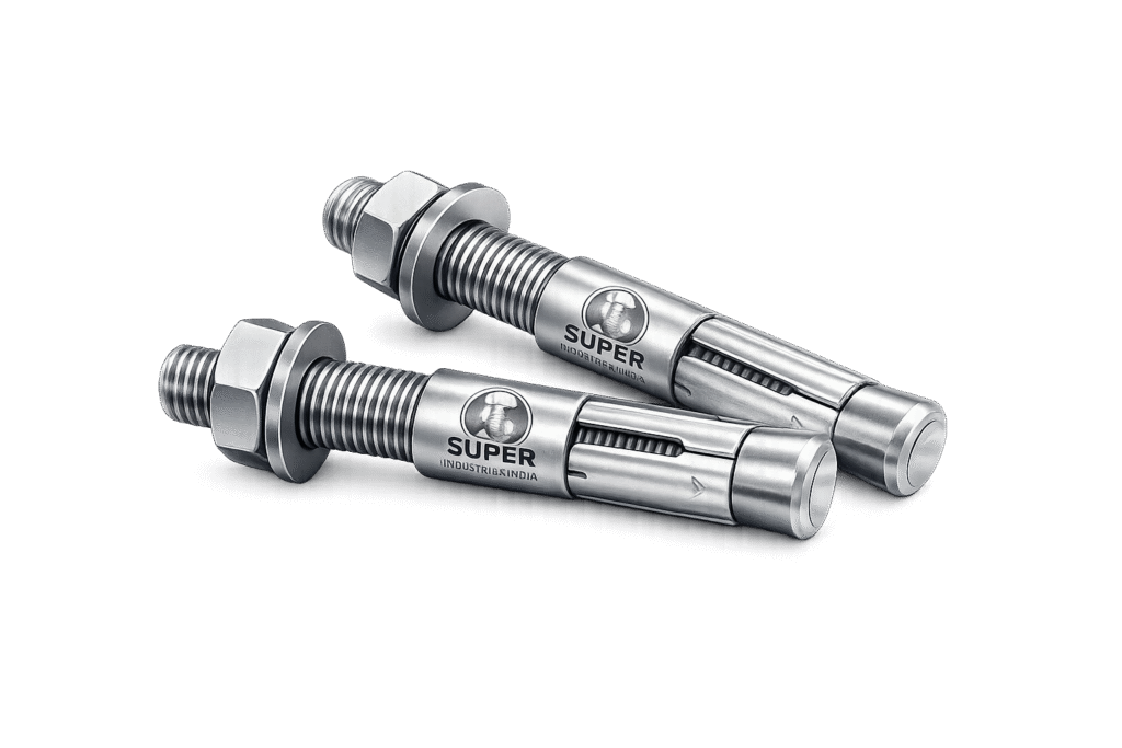
Role in Concrete Anchoring Systems
Sleeve Anchor Bolts are torque-controlled mechanical expansion anchors designed for fastening structural and non-structural elements into hardened concrete, masonry, and solid substrates. Within engineered anchoring systems, they function as post-installed anchors, transferring applied loads from fixtures into base concrete through a combination of frictional resistance and localized bearing pressure.
These anchors are widely used where:
- Pre-installed anchoring (cast-in systems) is not feasible
- Installation must occur after structural curing
- Flexibility in positioning is required
- Moderate to heavy loads are expected
Unlike adhesive or chemical anchoring systems, Sleeve Anchor Bolts provide immediate load-bearing capability after installation, subject to proper torque application.
Application Domains
Structural Steel Fixation
Used for base plates, brackets, and secondary steel connections where load transfer into concrete is required without embedded anchor cages.
Industrial Equipment Anchoring
Applied in securing rotating and static equipment such as:
- Pumps
- Compressors
- Generators
- Skid-mounted assemblies
Pipe Supports & Rack Systems
Used for:
- Pipe shoes
- Support brackets
- Modular rack anchoring
Oil & Gas Installations
Typical applications include:
- Platform walkways
- Cable tray supports
- Instrumentation mounting
Power Plants
Used in:
- Turbine auxiliary systems
- Switchyard equipment mounting
- Structural retrofits
Infrastructure & Civil Foundations
Applicable in:
- Bridge railings
- Barriers
- Signage supports
- Precast element anchoring
Heavy Machinery Installation
Supports dynamic load environments where proper torque application ensures reliable anchoring performance.
Selection Rationale: Mechanical Expansion Anchors
Sleeve Anchor Bolts are selected over alternative anchoring systems based on the following engineering considerations:
Compared to Cast-In Anchors
| Parameter | Sleeve Anchors | Cast-In Anchors |
|---|---|---|
| Installation Stage | Post-installed | Pre-concrete |
| Flexibility | High | Low |
| Alignment Adjustment | Possible | Limited |
| Retrofit Capability | Suitable | Not applicable |
Compared to Chemical Anchors
| Parameter | Sleeve Anchors | Chemical Anchors |
|---|---|---|
| Load Transfer | Mechanical expansion | Adhesive bonding |
| Cure Time | Immediate | Required |
| Installation Sensitivity | Moderate | High (cleanliness critical) |
| Temperature Sensitivity | Low | High |
Compared to Through Bolts
| Parameter | Sleeve Anchors | Through Bolts |
|---|---|---|
| Access Requirement | One-side | Two-side |
| Installation Depth | Controlled | Full thickness |
| Load Transfer | Localized | Full section |
Suitability: Cracked vs Non-Cracked Concrete
Sleeve Anchor Bolts are typically used in non-cracked concrete applications where:
- Load conditions are stable
- Crack width development is minimal
- Structural movement is limited
In cracked concrete, performance may be reduced due to:
- Loss of frictional engagement
- Reduced radial expansion effectiveness
For critical structural applications in cracked concrete, anchors complying with advanced approval systems (e.g., ETA or ICC-ES) are typically preferred.
2. Technical Definition of Sleeve Anchor Bolts
Engineering Definition
A Sleeve Anchor Bolt is a pre-assembled, torque-controlled mechanical expansion anchor consisting of a threaded fastener integrated with an expansion sleeve and conical expander mechanism.
It operates by generating radial expansion forces against the wall of a drilled hole when tightening torque is applied, enabling load transfer through:
- Friction between sleeve and concrete
- Bearing pressure against hole surface
Core Components
1. Threaded Stud / Bolt
- Primary load-carrying element
- Transfers tensile and shear loads from fixture to anchor system
- Available in multiple thread configurations (metric/UNC/UNF)
2. Expansion Sleeve
- Cylindrical sleeve surrounding the stud
- Expands radially upon cone movement
- Provides surface contact with concrete
3. Cone Expander
- Tapered component located at embedded end
- Drives sleeve expansion during tightening
- Critical for load transfer efficiency
4. Nut & Washer Assembly
- Applies axial force during tightening
- Controls torque input
- Ensures uniform load distribution on fixture
Types of Sleeve Anchor Bolts
Hex Head Sleeve Anchors
- Integral hex head
- Used for direct fastening without separate nut
- Common in structural and industrial applications
Stud Type Sleeve Anchors
- Threaded stud with external nut
- Allows flexibility in clamping thickness
- Preferred in adjustable installations
Flat Head / Countersunk Anchors
- Designed for flush surface installation
- Used in architectural or finishing applications
Through-Type Anchors
- Installed through fixture into concrete
- Eliminates need for pre-positioning anchor
- Common in field installations
Super Industries
Global Manufacturer of Heavy & Custom Engineered Fasteners & Flanges
3. Engineering & Load Transfer Principle
Expansion Mechanism Under Torque
Upon tightening the nut or bolt head:
- Axial tensile force is generated in the threaded element
- The cone expander is pulled into the expansion sleeve
- The sleeve expands radially against the drilled hole surface
- Contact pressure develops between sleeve and concrete
This process creates a mechanical interlock and frictional engagement.
Radial Force Generation
The radial expansion force ( F_r ) is a function of:
- Applied torque
- Thread geometry
- Cone angle
- Friction coefficient between components
This force is responsible for:
- Anchoring stability
- Resistance to pull-out loads
Load Transfer Mechanism
Load transfer occurs through two primary mechanisms:
1. Frictional Resistance
- Generated by radial pressure between sleeve and concrete
- Dominant in initial load stages
2. Bearing Resistance
- Developed due to localized compression of concrete
- Increases with load progression
Pull-Out Resistance Theory
Pull-out capacity depends on:
- Embedment depth
- Concrete compressive strength
- Sleeve expansion force
- Surface roughness of hole
Failure occurs when:
- Frictional resistance is exceeded
- Concrete surrounding anchor loses integrity
Shear Load Resistance
Shear loads are resisted through:
- Bearing of anchor shank against concrete
- Friction between fixture and base material
- Steel shear capacity
Design considerations include:
- Edge distance
- Anchor spacing
- Fixture rigidity
Combined Loading (Tension + Shear)
In real-world applications, anchors are subjected to combined loads.
Interaction behavior depends on:
- Load direction
- Anchor stiffness
- Concrete confinement
Design must consider interaction equations such as:
![\[\left( \frac{N}{N_{allow}} \right)^a + \left( \frac{V}{V_{allow}} \right)^b \leq 1\]](https://superindustriesindia.in/wp-content/ql-cache/quicklatex.com-2c8acbcb46bfd0347b2ccba5f8792f8a_l3.png "Rendered by QuickLaTeX.com")
Where:
- ( N ) = Applied tensile load
- ( V ) = Applied shear load
Concrete Failure Modes
1. Cone Failure
- Formation of conical fracture surface
- Occurs under high tensile load
- Dependent on embedment depth
2. Pull-Out Failure
- Anchor slips without concrete fracture
- Indicates insufficient expansion force
3. Steel Failure
- Occurs when anchor strength is exceeded
- Governed by material properties
4. Edge Breakout
- Occurs near free edges
- Controlled by edge distance and spacing
Behavior Under Load Progression
Load application sequence:
- Initial friction resistance
- Progressive bearing engagement
- Micro-cracking in concrete
- Ultimate failure mode (cone, steel, or pull-out)
Structural Reliability Considerations
Design reliability depends on:
- Proper installation torque
- Controlled embedment depth
- Concrete quality
- Environmental exposure
Sleeve Anchor Bolts are suitable for:
- Static loads
- Moderate dynamic loads (with proper design)
Not typically recommended for:
- High seismic or fatigue-critical anchoring without certification
4. Applicable Standards (ASTM / DIN / ISO / EN)
Sleeve Anchor Bolts used in EPC and infrastructure projects are evaluated against a combination of fastener standards, material specifications, and anchoring design codes. Compliance is not governed by a single standard but by an integrated framework.
ASTM Standards (Material & Mechanical Properties)
ASTM A307
- Covers carbon steel bolts up to 60 ksi tensile strength
- Applicable for general-purpose anchoring in non-critical structural applications
- Suitable for light to moderate load conditions
ASTM A193
- Alloy steel and stainless steel bolting for high-temperature or high-pressure service
- Relevant where anchors are exposed to elevated temperatures (e.g., power plants)
ASTM F593 / ASTM F594
- Stainless steel fasteners (SS304, SS316)
- Defines:
- Mechanical properties
- Chemical composition
- Thread class compatibility
Used in:
- Marine environments
- Chemical exposure conditions
- Corrosion-sensitive installations
DIN Standards (Dimensional & Assembly Control)
DIN 934
- Hexagon nuts dimensional standard
- Ensures compatibility with threaded studs
DIN 125
- Flat washers
- Load distribution across fixture surfaces
These standards ensure:
- Assembly uniformity
- Interchangeability across supply chains
- Dimensional compliance during inspection
ISO Standards (Global Fastener Framework)
ISO standards provide harmonization across global projects:
- ISO 898-1 → Mechanical properties of carbon steel fasteners
- ISO 3506 → Stainless steel fasteners
- ISO 4014 / 4017 → Hex bolts
Relevance:
- Defines property classes (8.8, 10.9)
- Establishes yield and tensile strength benchmarks
- Ensures cross-border procurement compatibility
EN Standards (Anchoring Design & Structural Compliance)
EN 1992-4 (Eurocode – Design of Fastenings in Concrete)
This is the primary design reference for:
- Load calculation of anchors
- Failure mode prediction
- Safety factor application
It governs:
- Tension resistance
- Shear resistance
- Edge distance and spacing
- Crack influence
ICC-ES (International Code Compliance – Optional)
Used primarily in:
- United States
- International EPC projects requiring evaluation reports
Provides:
- Performance validation
- Load rating certification
- Installation guidelines
Standards Mapping to Engineering Requirements
| Requirement | Governing Standard |
|---|---|
| Material strength | ASTM / ISO |
| Dimensional control | DIN / ISO |
| Corrosion resistance | ASTM / ISO |
| Load design | EN 1992-4 |
| Project compliance | ASTM + EN + Client specs |
Material & Grade Options
Material selection for Sleeve Anchor Bolts directly influences:
- Load capacity
- Corrosion resistance
- Service life
- Environmental suitability
Carbon Steel Anchors
ASTM A36
- Yield strength ~250 MPa
- Used in structural applications with moderate loading
- Requires protective coating for corrosion resistance
ASTM A307
- Lower strength compared to high-grade fasteners
- Suitable for general anchoring and non-critical applications
Stainless Steel Anchors
SS304 (A2)
- Good corrosion resistance in atmospheric conditions
- Suitable for humid and outdoor environments
SS316 (A4)
- Enhanced resistance to:
- Chlorides
- Marine exposure
- Chemical environments
Used in:
- Offshore platforms
- Coastal infrastructure
- Chemical plants
High Strength Steel Anchors
Property Class 8.8
- Yield strength: ~640 MPa
- Tensile strength: ~800 MPa
- Common in structural anchoring
Property Class 10.9
- Yield strength: ~940 MPa
- Tensile strength: ~1040 MPa
- Used in high-load applications
Material Selection Considerations
| Parameter | Carbon Steel | Stainless Steel | High Strength Steel |
|---|---|---|---|
| Strength | Moderate | Moderate | High |
| Corrosion Resistance | Low | High | Low (requires coating) |
| Cost | Lower | Higher | Moderate |
| Application | General | Corrosive | Heavy load |
Material Comparison Table (MANDATORY)
| Grade | Yield Strength (MPa) | Tensile Strength (MPa) | Corrosion Resistance | Temperature Suitability | Typical Application |
|---|---|---|---|---|---|
| ASTM A36 | ~250 | ~400–550 | Low | Moderate | Structural base anchoring |
| ASTM A307 | ~240 | ~415 | Low | Moderate | General fastening |
| SS304 | ~215 | ~505–700 | High | Up to ~400°C | Outdoor / humid |
| SS316 | ~205 | ~515–700 | Very High | Up to ~400°C | Marine / chemical |
| 8.8 | ~640 | ~800 | Low | Moderate | Structural anchoring |
| 10.9 | ~940 | ~1040 | Low | Moderate | Heavy-duty anchoring |
5. Heat Treatment Information
Heat treatment is applied primarily to high-strength Sleeve Anchor Bolts to achieve required mechanical properties.
Quenching & Tempering
Process:
- Heating to austenitizing temperature
- Rapid quenching (oil/water)
- Controlled tempering
Result:
- Increased strength
- Improved toughness
- Controlled hardness
Case Hardening (Selective Applications)
Used for:
- Wear resistance improvement
- Surface hardness enhancement
Not typically applied to all anchor types but may be used in specialized designs.
Stress Relieving
Applied after:
- Cold forming
- Thread rolling
Purpose:
- Reduce residual stresses
- Improve dimensional stability
Hardness Ranges
| Property Class | Hardness (HV) |
|---|---|
| 8.8 | ~250–320 |
| 10.9 | ~320–380 |
Metallurgical Considerations
Heat treatment affects:
- Grain structure refinement
- Dislocation density
- Fatigue resistance
Improper heat treatment may result in:
- Brittle fracture
- Reduced ductility
- Hydrogen embrittlement (if not controlled)
Manufacturing Process
The manufacturing of Sleeve Anchor Bolts follows a controlled, traceable sequence aligned with industrial fastener production practices.
Raw Material Inspection
Incoming material verification includes:
- Chemical composition analysis
- Mill test certificate validation
- Surface defect inspection
Wire Rod Processing
- Cleaning and descaling
- Straightening
- Cutting into blanks
Cold Forming / Hot Forging
Cold Forming
- Used for smaller diameters
- Provides better surface finish
- Maintains grain flow continuity
Hot Forging
- Used for larger diameters
- Enables complex geometries
Thread Rolling
- Threads formed through rolling dies
- Improves:
- Surface finish
- Fatigue resistance
- Dimensional accuracy
Sleeve Manufacturing
- Tube cutting
- Slotting (for expansion capability)
- Surface finishing
Critical parameters:
- Sleeve thickness
- Expansion slots geometry
Cone Expander Production
- Precision machining or cold forming
- Surface hardness control
- Taper angle accuracy
Assembly Process
Components assembled in sequence:
- Cone placed on stud
- Sleeve positioned
- Washer and nut installed
Ensures:
- Pre-assembled configuration
- Ease of installation
Heat Treatment (If Applicable)
- Conducted in controlled furnaces
- Batch traceability maintained
Surface Coating Application
Based on requirement:
- Electroplating
- Hot-dip galvanizing
- Mechanical plating
Final Inspection
Includes:
- Dimensional verification
- Thread gauge inspection
- Assembly fit check
Marking & Traceability
Each batch identified by:
- Heat number
- Grade marking
- Manufacturer identification
Ensures:
- Traceability to raw material
- Compliance with project documentation
6. Surface Finish Options
Surface protection is critical for durability and long-term anchoring performance.
Zinc Plating
- Thickness: 5–25 microns
- Suitable for indoor applications
- Moderate corrosion resistance
Hot-Dip Galvanizing (HDG)
- Thickness: 40–80 microns
- Suitable for outdoor and industrial environments
- Provides sacrificial protection
Mechanical Galvanizing
- Uniform coating
- Reduced risk of hydrogen embrittlement
- Suitable for high-strength fasteners
PTFE Coating
- Low friction
- Chemical resistance
- Used in specialized environments
Dacromet / Geomet Coating
- Zinc-aluminum flake coating
- High corrosion resistance
- Suitable for aggressive environments
Stainless Steel Passivation
- Enhances corrosion resistance
- Removes free iron contamination
Coating Selection vs Environment
| Environment | Recommended Finish |
|---|---|
| Indoor dry | Zinc plated |
| Outdoor | HDG |
| Marine | SS316 |
| Chemical | PTFE / Geomet |
| Industrial | HDG / Dacromet |
7. Inspection & Quality Control Methods
Sleeve Anchor Bolts supplied for EPC and infrastructure projects are subject to multi-stage inspection protocols to ensure compliance with dimensional, mechanical, and performance requirements.
Dimensional Inspection
Conducted using calibrated instruments:
- Vernier calipers
- Micrometers
- Thread gauges (GO / NO-GO)
Parameters verified:
- Anchor diameter
- Thread pitch and fit
- Sleeve length and thickness
- Overall assembly length
- Washer and nut dimensions
Proof Load Testing
Purpose:
- Verification of load-bearing capacity under controlled tensile load
Procedure:
- Anchor subjected to specified proof load (typically 60–70% of yield strength)
- No permanent deformation permitted
Pull-Out Testing
Simulates in-situ anchoring behavior.
Test variables:
- Concrete grade (e.g., C20/25, C30/37)
- Embedment depth
- Hole diameter
Measured output:
- Ultimate pull-out load
- Failure mode identification
Torque Testing
Ensures correct torque–tension relationship.
Parameters:
- Installation torque vs achieved preload
- Thread lubrication condition (dry/lubricated)
Hardness Testing
Methods:
- Vickers (HV)
- Rockwell (HRC)
Confirms:
- Heat treatment effectiveness
- Material grade compliance
Coating Thickness Testing
Methods:
- Magnetic thickness gauge
- Microscopic cross-section
Typical ranges:
- Zinc plating: 5–25 µm
- HDG: 40–80 µm
Non-Destructive Testing (NDT)
Magnetic Particle Inspection (MPI)
Applicable for:
- Surface crack detection in high-strength anchors
Visual Inspection
- Surface defects
- Coating uniformity
- Assembly correctness
Third-Party Inspection (TPI)
Inspection agencies may verify:
- Dimensional compliance
- Mechanical testing
- Documentation
Certification:
- EN 10204 3.1 (Mill test certificate)
- EN 10204 3.2 (Witnessed certification)
A. TECHNICAL DIMENSION TABLE
Typical dimensions (indicative values for standard Sleeve Anchor Bolts):
| Anchor Size | Drill Diameter (mm) | Embedment Depth (mm) | Max Fixture Thickness (mm) | Thread Size |
|---|---|---|---|---|
| M6 | 6 | 35–40 | 5–10 | M6 |
| M8 | 8 | 45–50 | 10–20 | M8 |
| M10 | 10 | 60–70 | 20–30 | M10 |
| M12 | 12 | 70–85 | 30–40 | M12 |
| M16 | 16 | 90–110 | 40–60 | M16 |
| M20 | 20 | 110–130 | 50–80 | M20 |
Dimensional Engineering Notes
- Drill diameter must match anchor nominal diameter
- Embedment depth directly influences pull-out resistance
- Fixture thickness must allow full sleeve expansion
- Thread engagement must remain above minimum required length
B. LOAD CAPACITY TABLE (REFERENCE VALUES)
For non-cracked concrete (C25/30), approximate safe working loads:
| Anchor Size | Tensile Load (kN) | Shear Load (kN) |
|---|---|---|
| M6 | 3 – 5 | 4 – 6 |
| M8 | 5 – 8 | 6 – 10 |
| M10 | 8 – 12 | 10 – 15 |
| M12 | 12 – 18 | 15 – 22 |
| M16 | 18 – 28 | 25 – 40 |
| M20 | 25 – 40 | 35 – 55 |
Load Engineering Notes
- Values depend on embedment depth and concrete strength
- Edge distance reduction factors must be applied
- Safety factors (typically 3–5) required for design
C. TORQUE CHART (MANDATORY)
Recommended installation torque values:
| Anchor Size | Torque (Nm) – Dry | Torque (Nm) – Lubricated | Property Class |
|---|---|---|---|
| M6 | 8 – 10 | 6 – 8 | 8.8 |
| M8 | 15 – 25 | 12 – 20 | 8.8 |
| M10 | 30 – 50 | 25 – 40 | 8.8 |
| M12 | 60 – 90 | 50 – 75 | 8.8 |
| M16 | 120 – 180 | 100 – 150 | 8.8 |
| M20 | 220 – 300 | 180 – 260 | 8.8 |
Torque Engineering Considerations
- Over-torquing may cause:
- Sleeve damage
- Concrete cracking
- Under-torquing may result in:
- Insufficient expansion
- Reduced pull-out resistance
D. PRELOAD & LOAD CALCULATION GUIDE (MANDATORY)
Torque–Tension Relationship
![\[F = \frac{T}{K \cdot d}\]](https://superindustriesindia.in/wp-content/ql-cache/quicklatex.com-047c3812ff26cb229181955bd579e870_l3.png "Rendered by QuickLaTeX.com")
Where:
- ( F ) = Preload force (N)
- ( T ) = Applied torque (Nm)
- ( K ) = Torque coefficient (0.18–0.25 typical)
- ( d ) = Nominal diameter (m)
Pull-Out Force Approximation
![\[F_{pull-out} = \tau \cdot \pi \cdot d \cdot L\]](https://superindustriesindia.in/wp-content/ql-cache/quicklatex.com-4384b54477d48f3c8044d873e803cb09_l3.png "Rendered by QuickLaTeX.com")
Where:
- ( \tau ) = Bond/shear stress of concrete
- ( d ) = Anchor diameter
- ( L ) = Embedment depth
Shear Force Capacity
![\[V = \tau_c \cdot A\]](https://superindustriesindia.in/wp-content/ql-cache/quicklatex.com-557edce65bfc5b5d6223917754a3444d_l3.png "Rendered by QuickLaTeX.com")
Where:
- ( \tau_c ) = Shear strength of concrete
- ( A ) = Cross-sectional area
Safety Factor Application
[
![\[F_{allowable} = \frac{F_{ultimate}}{SF}\]](https://superindustriesindia.in/wp-content/ql-cache/quicklatex.com-f7a0145f79e592b1b04c24321b4ea5b9_l3.png "Rendered by QuickLaTeX.com")
Typical Safety Factor:
- Static loads: 3–4
- Dynamic loads: 4–6
Sample Engineering Calculation
Given:
- Anchor size: M12
- Torque applied: 80 Nm
- Torque coefficient ( K = 0.2 )
- Diameter ( d = 0.012 , m )
Step 1: Preload Calculation
![\[F = \frac{80}{0.2 \times 0.012}\]](https://superindustriesindia.in/wp-content/ql-cache/quicklatex.com-38963d0af422469febc0867add89305f_l3.png "Rendered by QuickLaTeX.com")
![\[F = 33{,}333 \, \text{N}\]](https://superindustriesindia.in/wp-content/ql-cache/quicklatex.com-37a39eb54e0651452885268c73c84b79_l3.png "Rendered by QuickLaTeX.com")
Step 2: Allowable Load (SF = 4)
![\[F_{allowable} = \frac{33{,}333}{4} \approx 8{,}333 \, \text{N}\]](https://superindustriesindia.in/wp-content/ql-cache/quicklatex.com-333bbec5661bafa8e255a66eb838fc5f_l3.png "Rendered by QuickLaTeX.com")
Interpretation:
- Anchor must not be loaded beyond ~8.3 kN under given conditions
- Actual capacity must be verified with concrete strength and embedment
E. YIELD STRENGTH BEHAVIOR (ENGINEERING EXPLANATION)
Load vs deformation behavior of anchor steel:
- Elastic Region
- Linear stress–strain relationship
- No permanent deformation
- Yield Point
- Plastic deformation begins
- Permanent elongation occurs
- Strain Hardening
- Increased resistance with deformation
- Ultimate Strength
- Maximum load capacity
- Failure
- Necking and fracture
For anchoring systems:
- Design is typically limited below yield strength
- Ensures structural reliability and reusability margin
F. MECHANICAL PROPERTY TABLE
| Property Class | Yield Strength (MPa) | Tensile Strength (MPa) | Hardness (HV) | Elongation (%) |
|---|---|---|---|---|
| A307 | ~240 | ~415 | ~120–180 | ~20 |
| 8.8 | ~640 | ~800 | ~250–320 | ~12 |
| 10.9 | ~940 | ~1040 | ~320–380 | ~9 |
| SS304 | ~215 | ~505–700 | ~150–220 | ~40 |
| SS316 | ~205 | ~515–700 | ~150–220 | ~40 |
G. CORROSION RESISTANCE TABLE
| Material / Coating | Marine | Industrial | Humid | Chemical Exposure |
|---|---|---|---|---|
| Carbon Steel | Poor | Moderate | Poor | Poor |
| Zinc Plated | Low | Moderate | Moderate | Poor |
| HDG | Good | Good | Good | Moderate |
| SS304 | Moderate | Good | Good | Moderate |
| SS316 | Excellent | Excellent | Excellent | High |
| Dacromet / Geomet | Good | Excellent | Excellent | High |
8.PROCUREMENT & INSTALLATION VIEW
1. Drill Hole Preparation
- Drill diameter must match anchor specification
- Depth must exceed embedment by 5–10 mm
- Avoid oversized holes
2. Hole Cleaning Procedure
Critical for performance:
- Air blowing
- Brushing
- Re-blowing
Removes:
- Dust
- Loose particles
3. Anchor Insertion
- Insert through fixture (for through-type)
- Ensure full seating at hole bottom
4. Torque Tightening Sequence
- Use calibrated torque wrench
- Apply torque gradually
- Avoid impact tightening
5. Installation Errors to Avoid
- Over-drilling
- Inadequate cleaning
- Incorrect torque
- Improper embedment
6. Field Inspection Checklist
- Hole diameter verified
- Depth checked
- Torque applied as per specification
- Anchor alignment confirmed
7. Re-Tightening Practices
- Not generally required
- May be applied in vibration environments after initial settlement
8. Storage Requirements
- Dry environment
- Protection from moisture
- Avoid coating damage
9.Industries Served
Sleeve Anchor Bolts are deployed across multiple sectors where post-installed anchoring into concrete is required under defined load and environmental conditions. Application suitability depends on load class, installation control, and environmental exposure.
Oil & Gas Sector
Used in both upstream and downstream facilities:
Applications:
- Pipe support anchoring
- Cable tray systems
- Instrumentation stands
- Walkways and grating supports
- Skid-mounted equipment
Engineering Considerations:
- Exposure to hydrocarbons and corrosive environments
- Requirement for stainless steel or coated anchors
- Compliance with project specifications and inspection protocols
Power Generation Plants
Applicable across thermal, gas, and renewable facilities.
Applications:
- Auxiliary equipment anchoring
- Structural steel attachments
- Switchyard structures
- Control panel mounting
Engineering Considerations:
- Elevated temperatures in localized areas
- Vibration from rotating equipment
- Load stability under continuous operation
Infrastructure & Civil Engineering
Used in public and transportation infrastructure.
Applications:
- Bridge railings and barriers
- Lighting poles
- Signage structures
- Precast element fixing
Engineering Considerations:
- Outdoor exposure
- Variable loading conditions
- Long-term durability requirements
Industrial Plants & Process Facilities
Used in manufacturing and processing units.
Applications:
- Machine foundations
- Structural retrofits
- Maintenance platform anchoring
Engineering Considerations:
- Dynamic loads
- Chemical exposure
- Maintenance accessibility
Steel Structures & Fabrication
Used in secondary steel connections.
Applications:
- Brackets
- Support frames
- Retrofit anchoring
Engineering Considerations:
- Load transfer into existing concrete
- Alignment flexibility
- Installation efficiency
HVAC & Piping Systems
Applications:
- Pipe supports
- Ducting supports
- Equipment mounting
Engineering Considerations:
- Moderate loads
- Repetitive installation
- Accessibility constraints
Heavy Equipment Installation
Applications:
- Pumps
- Compressors
- Generators
Engineering Considerations:
- Dynamic loads and vibration
- Anchor preload stability
- Proper torque application
10. Export Capability & Global Supply
Super Industries supplies Sleeve Anchor Bolts for international EPC and infrastructure projects with documentation and logistics aligned to global procurement systems.
Export Regions
Supply coverage includes:
- United States
- European Union
- Middle East
- Southeast Asia
- Africa (project-based supply)
Packaging Standards
Packaging is designed to prevent:
- Mechanical damage
- Corrosion during transit
- Loss of traceability
Typical formats:
- Bulk cartons with inner lining
- Wooden crates for heavy shipments
- Palletized export units
Export Documentation
Supplied documentation includes:
- Commercial invoice
- Packing list
- Certificate of origin
- Mill test certificates (EN 10204 3.1 / 3.2)
- Inspection reports (if applicable)
Project Logistics
Logistics planning considers:
- Batch traceability
- Delivery scheduling aligned with site progress
- Container optimization for large-volume orders
Traceability & Identification
Each batch is traceable through:
- Heat number
- Manufacturing lot
- Inspection records
Ensures compliance with:
- EPC documentation requirements
- Third-party inspection validation
11.PROCUREMENT & INSTALLATION ENGINEERING VIEW
1. Procurement Considerations
For EPC and consultant-level evaluation, the following parameters are critical:
Technical Compliance
- Conformance to ASTM / ISO / EN standards
- Mechanical property verification
Material Selection
- Suitability for environment
- Corrosion resistance requirements
Load Requirements
- Tensile and shear capacity
- Safety factor application
Documentation
- Test certificates
- Inspection reports
- Traceability records
2. Installation Engineering Control
Proper installation directly affects anchor performance.
Drill Hole Control
- Diameter must match specification
- Depth must exceed embedment
- Avoid deviation or misalignment
Hole Cleaning
Mandatory for:
- Dust removal
- Proper sleeve contact
Procedure:
- Blow → Brush → Blow
Anchor Placement
- Insert to full depth
- Ensure proper seating
- Avoid partial embedment
Torque Application
- Use calibrated torque wrench
- Apply specified torque value
- Avoid impact tools
Post-Installation Verification
Check:
- Torque compliance
- Anchor alignment
- Fixture seating
3. Installation Errors & Engineering Impact
| Error | Impact |
|---|---|
| Oversized hole | Reduced expansion pressure |
| Under-torquing | Low pull-out resistance |
| Over-torquing | Concrete cracking / sleeve damage |
| Insufficient embedment | Reduced load capacity |
| Poor cleaning | Loss of friction |
4. Storage & Handling
To maintain integrity:
- Store in dry, covered environment
- Avoid exposure to moisture
- Prevent coating damage
- Maintain batch identification
12.CUSTOM ENGINEERING CAPABILITIES
Super Industries manufactures Sleeve Anchor Bolts with project-specific customization aligned to EPC requirements.
1. Non-Standard Sizes
- Custom diameters
- Extended lengths
- Special thread configurations
2. Custom Embedment Design
- Increased embedment for higher load
- Application-specific anchoring depth
3. Surface Coating Customization
- HDG with specified thickness
- PTFE for chemical environments
- Dacromet / Geomet systems
4. Material Customization
- Stainless steel grades (SS304 / SS316)
- High-strength alloy steel
5. Project-Specific Marking
- Grade identification
- Heat number
- Client-specific marking requirements
6. High-Load Anchoring Solutions
Design adjustments for:
- Increased load demand
- Harsh environmental conditions
- Specialized industrial applications
FINAL TECHNICAL POSITIONING
Sleeve Anchor Bolts function as torque-controlled mechanical expansion anchors designed for post-installed fastening into concrete where:
- Immediate load-bearing is required
- Installation flexibility is necessary
- Moderate to heavy loads must be transferred safely
Their performance is governed by:
- Expansion mechanism efficiency
- Concrete interaction behavior
- Installation accuracy
- Material and coating selection
From an EPC and structural engineering perspective, their suitability depends on:
- Correct load evaluation
- Compliance with applicable standards
- Controlled installation practices
- Verified inspection and documentation
When specified and installed within defined engineering parameters, Sleeve Anchor Bolts provide a reliable anchoring solution for non-cracked concrete applications across industrial, infrastructure, and energy sectors.
CONCLUDING ENGINEERING NOTE
Evaluation of Sleeve Anchor Bolts for project use must consider:
- Load demand vs anchor capacity
- Concrete condition (cracked vs non-cracked)
- Environmental exposure
- Installation control quality
These anchors are most effective when:
- Used within validated design limits
- Installed with calibrated torque control
- Supported by traceable manufacturing and inspection documentation