
U-NUTS
Super Industries
“Global Manufacturer of Heavy & Custom Engineered Fasteners for Oil & Gas, Power & EPC Contractors.”
1. Industry Context & System Relevance of U-NUTS
Role in Sheet Metal Fastening Systems
U-NUTS are deployed in sheet metal assemblies where conventional threaded fastening methods—such as tapping or welded nuts—are either inefficient or structurally unsuitable. These components function as self-retaining threaded anchors that eliminate the need for permanent thread creation in thin substrates.
Typical applications include:
- Thin gauge sheet assemblies (0.5 mm – 5 mm)
- Edge-mounted fastening zones
- Blind assembly interfaces
- Pre-fabricated modular panels
Their geometry allows installation without secondary machining or welding, maintaining the integrity of base material coatings and minimizing thermal distortion.
Relevance in Blind Assembly Conditions
In multiple industrial systems, access is restricted to one side of the panel. U-NUTS address this limitation by:
- Providing pre-installed threading capability
- Eliminating backside access requirements
- Supporting rapid assembly in constrained geometries
Typical blind applications:
- Automotive interior panels
- Electrical enclosures
- HVAC ducting systems
- Telecom cabinets
Use in Thin Panel Fastening
Tapped threads in thin sheets exhibit:
- Low thread engagement
- High strip-out probability
- Limited torque capacity
U-NUTS overcome these limitations by:
- Increasing effective thread engagement depth
- Distributing load across clip geometry
- Utilizing spring steel elasticity for retention
Automotive Body Structure Integration
Within automotive systems, U-NUTS are used in:
- Door panels
- Dashboard assemblies
- Trim and body cladding
- Underbody shielding
Engineering advantages:
- Compensation for tolerance variation
- Reduced assembly cycle time
- Elimination of weld spatter and rework
- Serviceability for maintenance operations
Electrical Enclosures & Panel Systems
In enclosure manufacturing:
- No welding requirement preserves coating systems (powder coat, galvanization)
- Enables modular assembly
- Supports repeated fastening cycles
Common use cases:
- Control panels
- Switchgear cabinets
- Junction boxes
HVAC & Ducting Systems
U-NUTS are applied in:
- Sheet metal ducts
- Air handling unit panels
- Insulation panel fastening
Advantages include:
- Rapid installation
- Reduced tooling dependency
- Compatibility with lightweight sheet materials
Rail & Infrastructure Panel Systems
Applications include:
- Coach interiors
- Panel cladding
- Cable management systems
Design requirements addressed:
- Vibration resistance
- Quick maintenance access
- Consistent torque retention
Why U-NUTS Instead of Welded Nuts or Tapped Holes
| Parameter | Welded Nut | Tapped Hole | U-NUTS |
|---|---|---|---|
| Heat Impact | Present | None | None |
| Installation Time | High | Moderate | Low |
| Reusability | Limited | Moderate | High |
| Surface Damage | High | Moderate | None |
| Alignment Flexibility | Fixed | Fixed | Adjustable (floating variants) |
| Tool Requirement | Welding setup | Tapping tools | None (pre-install clip) |
Assembly Efficiency in Mass Production
U-NUTS improve assembly line performance through:
- Pre-installation before main assembly stage
- Elimination of threading operations
- Reduction in takt time
- Lower operator dependency
Reusability and Serviceability
- Threads remain intact due to hardened structure
- Clips can be repositioned if required
- Replacement is non-destructive
Tool-less Pre-Installation
U-NUTS are installed by:
- Manual clipping onto panel edges
- No specialized tooling required
- Retained via spring force
2. Technical Definition of U-NUTS
Core Definition
U-NUTS are:
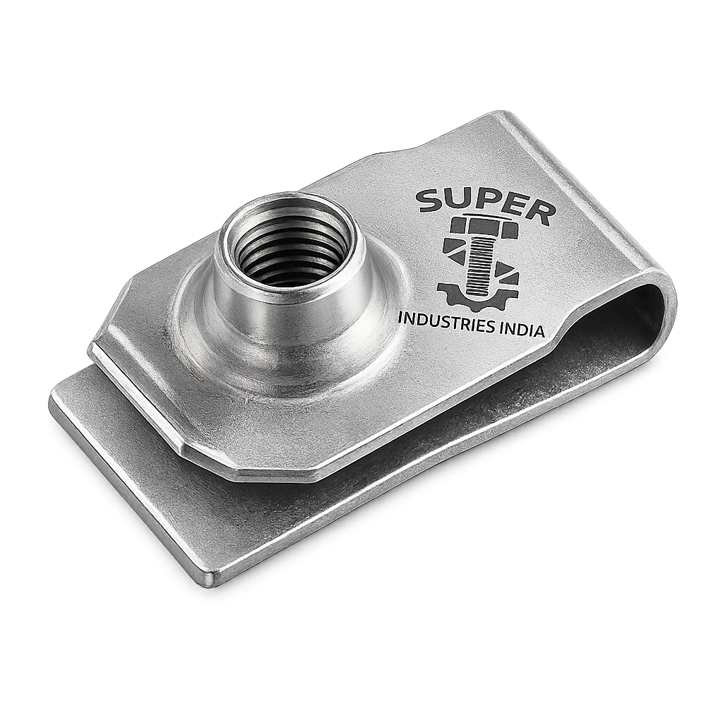
Self-retaining, clip-on threaded fasteners manufactured from spring steel, designed in a U-shaped channel form, used to provide threaded attachment points on sheet metal edges without tapping or welding.
Structural Characteristics
- U-shaped channel body
- One threaded leg (or extruded thread)
- One retaining leg
- Spring-loaded geometry
- Designed for edge mounting
Functional Characteristics
- Self-retaining on panel edge
- Provides internal thread engagement
- Allows repeated screw insertion
- Compensates for alignment variations
Types of U-NUTS
Standard U-NUTS
- Fixed thread alignment
- Used in general applications
- Suitable for consistent hole positioning
Extruded Thread U-NUTS
- Thread formed by extrusion
- Increased thread engagement depth
- Higher load capacity compared to stamped threads
Floating U-NUTS
- Thread element allows lateral movement
- Compensates for misalignment (±0.5 mm to ±1.0 mm typical)
- Used in automotive and enclosure systems
Heavy-Duty U-NUTS
- Thicker material construction
- Higher spring force
- Used in structural or vibration-prone assemblies
Metric vs UNC/UNF Variants
| Standard | Application Region |
|---|---|
| Metric (ISO) | Europe, Asia |
| UNC | North America |
| UNF | Precision automotive |
3. Engineering & Retention Principle of U-NUTS
Spring Force Retention Mechanism
The retention mechanism is based on:
- Elastic deformation of spring steel
- Clamping force generated between two legs of the U-profile
- Frictional resistance against panel surfaces
The clip exerts a normal force (N) on the panel, resulting in retention via friction.
Clip Tension vs Panel Thickness Interaction
Retention depends on:
- Clip opening gap
- Panel thickness
- Material elasticity
Condition:
- If panel thickness < design range → reduced retention
- If panel thickness > design range → installation difficulty or plastic deformation
Thread Engagement Mechanics
Thread engagement is achieved by:
- Formed or extruded thread inside the clip
- Engagement length greater than panel thickness
- Load transfer from screw → thread → clip body
Load Transfer Mechanism
Load path:
- Screw applies tensile force
- Force transferred to thread interface
- Load distributed across clip body
- Reaction force absorbed by panel edge
Anti-Slip and Anti-Rotation Behavior
- High friction interface prevents slip
- U-shape geometry restricts rotational movement
- Edge contact stabilizes position during torque application
Pull-Out Resistance Theory
Pull-out resistance is governed by:
- Friction coefficient (μ)
- Normal force (N)
- Contact area
Retention condition:
- Clip remains in position if applied force < frictional holding force
Strip-Out Failure Mode
Occurs when:
- Applied torque exceeds thread strength
- Material shear failure in thread region
Factors influencing:
- Material hardness
- Thread depth
- Screw class
Thread Deformation Mechanics
Under excessive load:
- Plastic deformation occurs in thread flanks
- Leads to reduced preload
- May result in loosening under vibration
Friction-Based Retention
Retention is a function of:
- Surface finish of panel
- Coating thickness
- Clip surface condition
Higher friction → improved retention stability
Functional Summary
U-NUTS operate as:
- A combined spring clip + threaded fastener
- Providing both mechanical retention and load-bearing capability
- Without permanent modification of base material
4. Applicable Standards (ISO / DIN / ASTM)
Overview of Standardization Framework
U-NUTS are not governed by a single unified global dimensional standard; however, their design, thread systems, materials, and performance characteristics are derived from established international standards. Compliance is typically ensured through a combination of DIN, ISO, ASTM, and IFI references.
DIN 7965 – Speed Nuts (Primary Reference)
DIN 7965 is the principal reference standard for speed nuts and clip nuts, covering:
- Dimensional envelopes
- Clip geometry
- Functional performance expectations
- Thread positioning and tolerances
Engineering Relevance
- Establishes baseline geometry for U-type clips
- Ensures interchangeability across suppliers
- Widely referenced in automotive and enclosure manufacturing
ISO Metric Thread Standards
Threading within U-NUTS follows ISO metric thread systems:
- ISO 261 – General plan for metric screw threads
- ISO 965 – Tolerances for metric threads
- ISO 68-1 – Basic profile for metric threads
Engineering Implications
- Ensures compatibility with standard fasteners (bolts/screws)
- Maintains consistent pitch and flank angle
- Defines tolerance classes (6H typical for internal threads)
Unified Thread Standards (UNC / UNF)
For North American applications:
- UNC (Unified National Coarse)
- UNF (Unified National Fine)
Usage Context
- Automotive OEM exports
- Equipment supplied to US-based EPC contractors
- Retrofit and maintenance compatibility
ASTM Material Standards
Material compliance is aligned with ASTM specifications for spring steel and stainless steel:
Carbon Spring Steel
- ASTM A684 – High carbon spring steel strip
Stainless Steel
- ASTM A240 – Stainless steel sheet/strip
IFI (Industrial Fasteners Institute) References
IFI standards are used for:
- Dimensional guidance
- Performance benchmarking
- Torque and load characteristics
Standard Mapping to Applications
| Application Sector | Governing Standard(s) | Engineering Requirement |
|---|---|---|
| Automotive OEM | DIN 7965, ISO, IFI | High repeatability, vibration resistance |
| Electrical Enclosures | ISO, ASTM | Corrosion resistance, modular assembly |
| HVAC Systems | DIN, ASTM | Lightweight fastening, ease of installation |
| Rail & Infrastructure | ISO, ASTM | Fatigue resistance, durability |
| Industrial Machinery | ISO, IFI | Load-bearing consistency |
Compliance Summary
U-NUTS supplied for EPC and OEM applications are typically:
- Dimensionally aligned with DIN 7965
- Thread-compliant with ISO/UNC/UNF standards
- Material-certified per ASTM specifications
- Verified through internal and third-party inspection protocols
5. Material & Grade Options
Material selection is critical for ensuring:
- Spring retention capability
- Thread strength
- Corrosion resistance
- Fatigue life
Carbon Spring Steel
Common Grades
- SAE 1074
- SAE 1075
- EN 10132 (C75S equivalent)
Engineering Characteristics
- High yield strength
- Excellent elastic recovery
- Suitable for repeated deflection
- Requires protective coating for corrosion resistance
Stainless Steel
Common Grades
- AISI 301
- AISI 304
Engineering Characteristics
- Moderate to high strength (work-hardened condition)
- Intrinsic corrosion resistance
- Lower spring recovery compared to carbon spring steel (unless cold worked)
Mechanical Behavior Considerations
| Property | Carbon Spring Steel | Stainless Steel |
|---|---|---|
| Yield Strength | High | Moderate |
| Elastic Recovery | Excellent | Moderate |
| Corrosion Resistance | Requires coating | Inherent |
| Fatigue Resistance | High | Moderate |
| Formability | Controlled | Good |
Material Comparison Table
| Material Grade | Yield Strength (MPa) | Tensile Strength (MPa) | Spring Property | Corrosion Resistance | Typical Application |
|---|---|---|---|---|---|
| SAE 1074 | 900–1100 | 1100–1400 | High | Low (coated) | Automotive clips |
| SAE 1075 | 950–1200 | 1200–1500 | High | Low (coated) | Heavy-duty U-NUTS |
| EN 10132 (C75S) | 900–1150 | 1100–1450 | High | Low (coated) | Industrial panels |
| AISI 301 | 700–1000 | 1000–1300 | Moderate-High | High | Enclosures, HVAC |
| AISI 304 | 600–900 | 900–1200 | Moderate | High | Corrosion-prone environments |
Material Selection Logic
Selection depends on:
- Environmental exposure (corrosive vs controlled)
- Required spring force
- Load conditions
- Cost constraints
- Lifecycle expectations
6. Heat Treatment Engineering
Heat treatment is essential for achieving:
- Required hardness
- Spring characteristics
- Elastic memory
Hardening Process
- Heating to austenitizing temperature (approx. 800–900°C)
- Rapid quenching (oil/water)
Result:
- Increased hardness
- Formation of martensitic structure
Tempering Process
- Controlled reheating (200–500°C)
- Reduces brittleness
- Improves toughness
Spring Temper Generation
Spring temper ensures:
- Elastic deformation without permanent set
- Repeatable clip engagement
Stress Relieving
Post-forming stress relief:
- Removes residual stresses from stamping and bending
- Prevents cracking during service
Hardness Range
Typical hardness:
- Carbon Spring Steel U-NUTS: 38–48 HRC
- Stainless Steel (Cold Worked): 25–40 HRC
Elastic Recovery Properties
Defined by:
- Modulus of elasticity
- Heat treatment condition
Ensures:
- Clip returns to original shape after installation
- Maintains retention force over multiple cycles
Fatigue Life Impact
Proper heat treatment:
- Enhances resistance to cyclic loading
- Reduces crack initiation probability
- Extends operational life in vibration environments
7. Manufacturing Process of U-NUTS
Manufacturing follows a controlled, repeatable, high-volume stamping and forming process.
Raw Material Inspection
- Verification of chemical composition
- Coil thickness tolerance check
- Surface defect inspection
Blanking & Stamping
- High-speed progressive dies used
- Blanking defines outer profile
- Piercing for thread zone (if required)
Forming (U-Shape Bending)
- Precision bending operations
- Controlled angle and radius
- Spring-back compensation
Thread Forming / Tapping
Two approaches:
Extruded Thread Formation
- Material displaced to create thread height
- Higher strength due to grain continuity
Tapped Threads
- Machined threads
- Used in thicker variants
Heat Treatment
- Hardening and tempering applied
- Batch or continuous furnace systems
Surface Coating
Applied based on application requirement:
- Corrosion protection
- Friction control
- Aesthetic uniformity
Final Inspection
Includes:
- Dimensional verification
- Thread gauge inspection
- Hardness testing
- Surface finish validation
Batch Traceability
Maintained through:
- Heat number tracking
- Production batch identification
- Inspection records
Tooling Precision & Die Maintenance
Critical factors:
- Die wear directly affects dimensional accuracy
- Regular maintenance ensures:
- Consistent clip tension
- Accurate thread alignment
- Repeatable performance
8. Surface Finish Options
Surface finish directly impacts:
- Corrosion resistance
- Friction during tightening
- Service life
Zinc Plating
- Thickness: 5–12 microns
- Corrosion resistance: 48–96 hours (salt spray)
Zinc-Nickel Coating
- Higher corrosion resistance (300–720+ hours)
- Suitable for automotive and outdoor use
Phosphate Coating
- Provides base for lubrication
- Moderate corrosion resistance
- Used in controlled environments
Black Oxide
- Minimal corrosion protection
- Used for indoor or low-exposure applications
Passivation (Stainless Steel)
- Enhances corrosion resistance
- Removes free iron contamination
Coating Impact on Torque
- Coatings alter friction coefficient
- Affects torque-to-clamp relationship
- Must be considered during assembly specification
Corrosion Performance Summary
| Coating Type | Salt Spray Resistance | Application |
|---|---|---|
| Zinc Plated | 48–96 hrs | Indoor / light exposure |
| Zinc-Nickel | 300–720+ hrs | Automotive / outdoor |
| Phosphate | 24–48 hrs | Controlled environments |
| Black Oxide | <24 hrs | Indoor |
| Stainless + Passivation | 500+ hrs | Marine / high humidity |
A. Technical Dimension Tables
Dimensional control of U-NUTS is critical to ensure:
- Proper panel fitment
- Adequate spring retention
- Thread alignment consistency
- Assembly repeatability
The following table represents typical engineering ranges used in industrial and automotive applications.zz
Standard Dimension Table (Metric U-NUTS)
| Thread Size | Panel Thickness Range (mm) | Clip Width (mm) | Hole Size Compatibility (mm) | Material Thickness (mm) |
|---|---|---|---|---|
| M4 | 0.5 – 1.5 | 8 – 10 | 4.2 – 4.5 | 0.5 – 0.8 |
| M5 | 0.7 – 2.0 | 10 – 12 | 5.2 – 5.5 | 0.6 – 1.0 |
| M6 | 1.0 – 2.5 | 12 – 14 | 6.2 – 6.6 | 0.8 – 1.2 |
| M8 | 1.5 – 3.0 | 14 – 18 | 8.2 – 8.6 | 1.0 – 1.5 |
| M10 | 2.0 – 4.0 | 18 – 22 | 10.2 – 10.6 | 1.2 – 2.0 |
| M12 | 2.5 – 5.0 | 22 – 26 | 12.2 – 12.6 | 1.5 – 2.5 |
Engineering Notes
- Panel thickness must fall within specified grip range to maintain retention force
- Excess clearance leads to clip movement and misalignment
- Tight fit improves vibration resistance but may increase installation force
B. Load Capacity Table
Load capacity depends on:
- Material strength
- Thread engagement depth
- Clip geometry
- Installation torque
Typical Load Ratings
| Thread Size | Tensile Load (N) | Shear Load (N) | Recommended Torque (Nm) | Safety Factor (Typical) |
|---|---|---|---|---|
| M4 | 800 – 1200 | 600 – 900 | 2 – 3 | 2.5 – 3 |
| M5 | 1200 – 1800 | 900 – 1400 | 4 – 6 | 2.5 – 3 |
| M6 | 1800 – 3000 | 1400 – 2200 | 8 – 10 | 2 – 2.5 |
| M8 | 3000 – 5000 | 2500 – 4000 | 18 – 25 | 2 – 2.5 |
| M10 | 5000 – 8000 | 4000 – 6500 | 35 – 50 | 2 |
| M12 | 8000 – 12000 | 6500 – 10000 | 60 – 80 | 1.8 – 2 |
Engineering Interpretation
- Tensile values governed by thread stripping limits
- Shear values depend on clip-to-panel interface
- Safety factor must be adjusted based on application criticality
C. Torque Chart
Torque control is essential to prevent:
- Thread stripping
- Clip deformation
- Loss of preload
Torque vs Thread Size
| Thread Size | Dry Torque (Nm) | Lubricated Torque (Nm) | Typical Screw Class |
|---|---|---|---|
| M4 | 2.5 | 2.0 | 8.8 |
| M5 | 5.0 | 4.0 | 8.8 |
| M6 | 9.0 | 7.5 | 8.8 |
| M8 | 22.0 | 18.0 | 8.8 |
| M10 | 45.0 | 38.0 | 8.8 |
| M12 | 75.0 | 65.0 | 8.8 |
Torque–Clamp Force Relationship
\[
T = K \cdot F \cdot d
\]
Where:
- (T) = tightening torque
- (K) = friction factor (0.15–0.25 depending on coating)
- (F) = clamp force
- (d) = nominal diameter
Engineering Considerations
- Coating type alters friction factor
- Over-torque leads to thread deformation
- Under-torque results in joint loosening
D. Retention & Pull-Out Calculation Guide
Retention performance is governed by frictional holding capacity of the clip.
Retention Force Formula
\[
F_{\text{retention}} = \mu \cdot N
\]
Where:
- (F_{retention}) = holding force
- (\mu) = coefficient of friction
- (N) = normal force exerted by clip
Extended Pull-Out Consideration
For enhanced modeling:
\[
F_{\text{pull-out}} = \mu \cdot N + A \cdot \tau
\]
Where:
- (A) = contact area
- (\tau) = shear strength at interface
Sample Engineering Calculation
Assume:
- (\mu = 0.2) (zinc-plated steel interface)
- (N = 150 , N)
Result:
\[
F_{\text{retention}} = 0.2 \times 150 = 30 \, \text{N}
\]
Interpretation:
- Clip will resist up to 30 N before sliding
- Additional resistance may come from edge constraints
Engineering Notes
- Higher spring force increases retention
- Surface roughness increases friction
- Coatings reduce or stabilize friction coefficient
E. Mechanical Property Table
Mechanical properties define performance under load and deformation.
Material Mechanical Properties
| Material | Yield Strength (MPa) | Tensile Strength (MPa) | Hardness (HRC) | Elastic Modulus (GPa) |
|---|---|---|---|---|
| SAE 1074 | 900 – 1100 | 1100 – 1400 | 40 – 48 | ~210 |
| SAE 1075 | 950 – 1200 | 1200 – 1500 | 42 – 50 | ~210 |
| EN 10132 C75 | 900 – 1150 | 1100 – 1450 | 40 – 48 | ~210 |
| AISI 301 | 700 – 1000 | 1000 – 1300 | 30 – 40 | ~193 |
| AISI 304 | 600 – 900 | 900 – 1200 | 25 – 35 | ~193 |
Engineering Interpretation
- Higher hardness improves wear resistance
- Higher yield strength improves spring retention
- Elastic modulus governs deflection characteristics
F. Corrosion Resistance Comparison Table
Corrosion resistance must be matched to service environment.
Comparative Table
| Material / Coating | Outdoor | Marine | High Humidity | Industrial |
|---|---|---|---|---|
| Carbon Steel (Zinc Plated) | Moderate | Low | Moderate | Moderate |
| Carbon Steel (Zn-Ni) | High | Moderate | High | High |
| Stainless Steel (AISI 304) | High | High | High | High |
| Phosphate Coated | Low | Very Low | Low | Moderate |
| Black Oxide | Very Low | Very Low | Low | Low |
Engineering Selection Logic
- Marine → Stainless steel or Zn-Ni
- Indoor industrial → Zinc plated
- High humidity → Stainless or Zn-Ni
9. Inspection & Quality Control Methods
Inspection ensures dimensional accuracy, material integrity, and performance reliability.
Thread Gauge Inspection
- Go/No-Go gauges used
- Ensures compliance with ISO/UNC tolerances
- Detects thread deformation or undersizing
Hardness Testing
- Rockwell hardness (HRC scale)
- Confirms heat treatment effectiveness
- Ensures spring performance
Coating Thickness Measurement
- XRF or micrometer methods
- Ensures corrosion protection compliance
Salt Spray Testing
- Conducted as per ASTM B117
- Measures corrosion resistance performance
- Validates coating systems
Dimensional Inspection
- Vernier, micrometer, profile projectors
- Critical dimensions:
- Clip width
- Material thickness
- Thread alignment
Spring Force Validation
- Compression testing
- Measures retention force
- Ensures consistent clip tension
Functional Fitment Testing
- Panel fit verification
- Screw engagement validation
- Torque testing under simulated conditions
Third-Party Inspection (TPI)
Inspection agencies may verify:
- Dimensional compliance
- Material certification
- Coating validation
- Mechanical performance
Documentation & Certification
- EN 10204 3.1 Mill Test Certificate
- Batch traceability records
- Inspection reports
Quality Control Summary
Quality assurance is maintained through:
- In-process inspection
- Final inspection protocols
- Documentation traceability
- Compliance with EPC procurement requirements
10. Industries Served
U-NUTS are deployed across multiple engineering sectors where sheet metal fastening, rapid assembly, and serviceability are required. Their selection is typically driven by panel thickness constraints, accessibility limitations, and production efficiency requirements.
Automotive OEM & Tier Suppliers
Applications
- Body panels and trims
- Dashboard and interior assemblies
- Underbody protection panels
- Electrical mounting brackets
Engineering Requirements
- Vibration resistance under dynamic loading
- Compatibility with automated assembly lines
- Tolerance compensation (floating variants)
- Repeatable torque retention
Design Considerations
- High cycle fatigue resistance
- Uniform coating performance for corrosion protection
- Consistent spring force across production batches
Electrical Enclosures & Switchgear Systems
Applications
- Control panels
- Junction boxes
- Switchgear cabinets
- Modular enclosures
Engineering Requirements
- No welding to preserve powder coating integrity
- Modular assembly capability
- Reusability during maintenance
Performance Considerations
- Thread durability under repeated fastening cycles
- Corrosion resistance in indoor/outdoor installations
HVAC Systems
Applications
- Air ducts
- Air handling unit (AHU) panels
- Insulation panel fixing
Engineering Requirements
- Lightweight fastening systems
- Rapid installation during site assembly
- Compatibility with galvanized sheet metal
Railways & Transportation Infrastructure
Applications
- Coach interiors
- Panel cladding systems
- Cable routing brackets
Engineering Requirements
- Resistance to vibration and shock loads
- Long service life with minimal maintenance
- Consistent retention in cyclic loading conditions
Telecom & Data Infrastructure
Applications
- Server racks
- Telecom cabinets
- Equipment mounting panels
Engineering Requirements
- High density assembly
- Fast installation and removal
- Dimensional consistency for rack systems
Industrial Machinery & Equipment
Applications
- Machine guards
- Access panels
- Electrical housings
Engineering Requirements
- Serviceability for maintenance operations
- Resistance to industrial environmental conditions
- Secure fastening under operational loads
Infrastructure & Panel Systems
Applications
- Architectural cladding panels
- Utility enclosures
- Control systems in infrastructure projects
Engineering Requirements
- Corrosion resistance in outdoor environments
- Ease of installation at site conditions
- Compatibility with prefabricated panel systems
11. Export Capability & Global Supply
Super Industries supplies U-NUTS to global markets aligned with EPC contractor requirements, OEM specifications, and international inspection protocols.
Regions Served
- United States
- European Union
- Middle East (UAE, Saudi Arabia, Qatar)
- Southeast Asia
- Africa (project-based supply)
Packaging Systems
Packaging is designed to prevent corrosion and mechanical damage during transit.
Standard Packaging Options
- Bulk packaging (HDPE-lined cartons)
- Export-grade corrugated boxes
- Palletized loads with stretch wrapping
- Vacuum or VCI (Volatile Corrosion Inhibitor) packaging
Kitting & Project Packaging
- Custom kit formation based on BOM
- Pre-counted fastener sets for assembly lines
- Labeling aligned with project documentation
Export Documentation
Documentation provided includes:
- Commercial invoice
- Packing list
- Certificate of origin
- EN 10204 3.1 material test certificate
- Inspection reports (if applicable)
Container Loading Discipline
- Load distribution to prevent deformation
- Moisture protection using desiccants
- Segregation of coated vs uncoated products
- Batch traceability maintained at shipment level
Project Supply Capability
- High-volume production for EPC projects
- Scheduled deliveries aligned with project timelines
- Capability for repeat orders with consistent specifications
12. Procurement & Installation Engineering View
Installation Method
Step-by-Step Installation
- Align U-NUTS with panel edge
- Apply manual pressure to clip onto sheet
- Ensure full seating and alignment with hole
- Insert mating screw/bolt
- Apply specified torque
Installation Characteristics
- No pre-threading required
- No welding or riveting
- No specialized installation tools
Screw Insertion & Torque Control
- Use torque-controlled tools for repeatability
- Avoid over-tightening to prevent thread strip
- Consider lubrication effect of coating
Reusability Limits
- Threads typically support multiple fastening cycles
- Clip retention force may reduce after repeated removal
- Replacement recommended if:
- Loss of spring tension
- Visible deformation
- Thread wear
Replacement Guidelines
- Remove using manual disengagement
- Replace with identical specification
- Verify panel thickness compatibility
Assembly Line Efficiency
U-NUTS contribute to:
- Reduced assembly cycle time
- Lower tooling cost
- Improved consistency in fastening operations
Custom Engineering Capabilities
Super Industries supports application-specific customization based on engineering requirements.
Custom Thread Sizes
- Metric (M3 – M12+)
- UNC / UNF variants
Special Clip Geometries
- Extended leg designs
- High-retention variants
- Double-thread configurations
High-Grip Designs
- Increased spring force for critical applications
- Optimized for vibration-prone systems
Coating-Specific Solutions
- Zinc-nickel for automotive environments
- Stainless steel for marine applications
- Project-specific coating thickness control
Automotive-Grade Validation
- PPAP documentation (on request)
- Dimensional capability studies
- Batch-level inspection records
13. Engineering Summary & Functional Evaluation
U-NUTS function as a combined:
- Spring retention device
- Threaded fastening interface
They are engineered to:
- Eliminate tapping and welding operations
- Improve assembly efficiency
- Maintain serviceability of sheet metal systems
Performance Capabilities
- Reliable thread engagement in thin materials
- Consistent retention through spring force
- Compatibility with standard fasteners
- Resistance to moderate vibration conditions
Limitations (Engineering Perspective)
- Lower load capacity compared to welded nuts
- Dependent on panel thickness compatibility
- Sensitive to over-torque conditions
- Retention influenced by surface condition and coating
Selection Criteria Summary
| Parameter | Engineering Consideration |
|---|---|
| Panel Thickness | Must match clip grip range |
| Load Requirement | Within thread capacity |
| Environment | Determines material/coating |
| Assembly Method | Manual vs automated |
| Reusability | Required or not |
Conclusion (EPC & Engineering Perspective)
U-NUTS provide a standardized and efficient solution for threaded fastening in sheet metal assemblies where:
- Access is limited
- Material thickness restricts tapping
- Assembly speed is critical
Their engineering value lies in:
- Spring-based retention mechanics
- Adaptability to tolerance variations
- Compatibility with global fastener standards
From an EPC and OEM evaluation standpoint, U-NUTS are suitable for:
- Non-structural fastening applications
- Modular panel systems
- High-volume production environments
Final Engineering Statement
This document presents U-NUTS as a technically defined, standards-aligned fastening solution suitable for evaluation in:
- Automotive systems
- Electrical enclosures
- Infrastructure panel assemblies
- Industrial equipment manufacturing
Super Industries supplies U-NUTS with controlled material properties, dimensional consistency, and inspection-backed quality systems aligned with global procurement and engineering requirements.