
CLIP NUTS
Super Industries
“Global Manufacturer of Heavy & Custom Engineered Fasteners for Oil & Gas, Power & EPC Contractors.”
1. Industry Context & Assembly Relevance
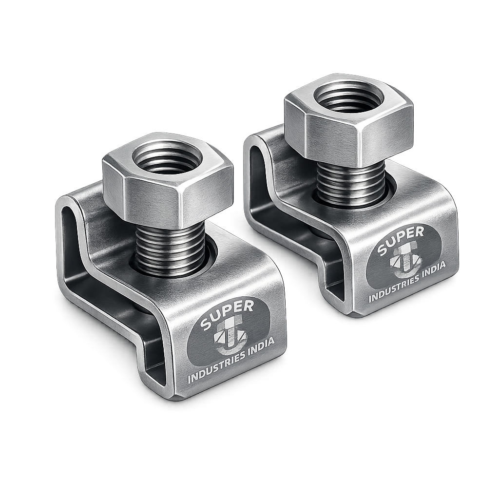
CLIP NUTS are widely deployed in thin sheet metal fastening systems where direct thread formation (tapping) or welded nut integration is either structurally inefficient, cost-intensive, or operationally restrictive. These fasteners provide localized, reusable threaded engagement without requiring permanent modification to the base material.
They are particularly relevant in modular, serviceable, and field-installable assemblies, where accessibility, replaceability, and alignment tolerance are critical.
Primary Application Domains
Automotive Body & Trim Systems
- Door panels, dashboards, fenders, and interior trims
- Battery enclosures and underbody shielding
- Mounting points for electronic modules and brackets
Electrical Panels & Enclosures
- LV/MV panel covers
- Junction boxes and distribution boards
- Control cabinets and industrial automation panels
HVAC & Air Handling Systems
- Duct panels and access covers
- Equipment housings
- Filter compartments
Rail Coaches & Infrastructure
- Interior paneling and ceiling modules
- Equipment mounting brackets
- Cable routing panels
Server Racks & Data Centers
- Rack mounting systems
- Cable management panels
- Equipment support rails
Industrial Machinery & Equipment Covers
- Protective guards and removable covers
- Access panels for maintenance
- Operator interface housings
Telecom Cabinets
- Outdoor enclosures
- Network equipment housings
- Mounting frames
Why CLIP NUTS Are Preferred Over Alternative Methods
1. Limitations of Welded Nuts
- Heat-affected zone (HAZ) alters base material properties
- Risk of weld failure under vibration
- Distortion in thin sheet sections
- Additional fabrication steps (welding + inspection)
2. Limitations of Tapped Holes
- Insufficient thread engagement in thin sheets (<3 mm typical)
- High stripping probability under torque
- Not reusable after thread damage
- Increased machining cost
3. Advantages of CLIP NUTS
| Engineering Factor | CLIP NUTS Advantage |
|---|---|
| Thin Sheet Compatibility | Provides full thread engagement independent of sheet thickness |
| Assembly Flexibility | Can be installed post-fabrication |
| Replaceability | Easily removable and replaceable |
| No Heat Input | Eliminates welding distortion |
| Alignment Compensation | Allows minor misalignment correction |
| Cost Efficiency | Reduces machining and welding operations |
Field Assembly & Maintenance Benefits
- Enables blind-side installation in restricted access areas
- Supports modular replacement without structural damage
- Facilitates maintenance cycles without thread degradation
- Reduces downtime in industrial and infrastructure systems
Super Industries
Global Manufacturer of Heavy & Custom Engineered Fasteners & Flanges
2. Technical Definition
Definition of CLIP NUTS
CLIP NUTS are self-retaining threaded fastening elements consisting of a spring steel or stainless steel clip body integrated with a threaded feature, designed to attach onto thin sheet metal edges or pre-punched holes.
They function as captive nuts, providing a load-bearing threaded interface without requiring tapping, welding, or permanent deformation of the base structure.
Core Functional Characteristics
- Self-retaining mechanism via spring tension
- Pre-formed or integrated thread
- Designed for thin sheet engagement (0.5 mm to ~6 mm typical)
- Removable and reusable within defined limits
- Compatible with standard metric fasteners (ISO threads)
Types of CLIP NUTS
1. U-Type CLIP NUTS
- Most widely used configuration
- U-shaped clip fits over sheet edge
- Internal threaded feature aligned with hole
Application: Automotive panels, enclosures, HVAC units
2. J-Type CLIP NUTS
- Asymmetrical design for one-sided engagement
- Used where edge access is limited
Application: Tight assembly zones, offset mounting
3. Screw CLIP NUTS
- Pre-attached or integrated screw mechanism
- Reduces assembly time
Application: High-speed assembly lines
4. Floating CLIP NUTS
- Threaded portion allows lateral movement
- Compensates for misalignment
Application: Multi-panel assemblies, tolerance-sensitive systems
5. Extruded CLIP NUTS
- Feature extended thread length via extrusion
- Increased load-bearing capacity
Application: Higher load requirements in thin sheets
Thread Standards
- ISO Metric Threads (M4 – M12 typical range)
- UNC/UNF threads available for export requirements
- Thread class typically 6H (metric internal thread standard)
3. Mechanical & Retention Principle
Spring Tension Retention Mechanism
The primary retention mechanism of CLIP NUTS is based on elastic deformation of the clip body, which generates normal force against the sheet metal surface.
When installed:
- The clip arms deflect outward
- Upon seating, they exert constant clamping pressure
- This pressure ensures positional stability and anti-slip behavior
Thread Engagement Behavior
Unlike tapped holes:
- Thread engagement is independent of base material thickness
- Engagement length is defined by the clip nut geometry
- Provides consistent load-bearing thread profile
Load Transfer Mechanism
Load path during fastening:
- Screw applies axial load
- Load transfers to internal thread of clip nut
- Clip body distributes load to sheet metal via:
- Contact surfaces
- Edge engagement
- Frictional retention
Anti-Rotation Design
CLIP NUTS prevent rotation through:
- Mechanical interlocking with sheet edge
- Surface friction from spring force
- Geometry-based resistance (U-shape constraint)
Clip Grip Force vs Panel Thickness
Grip force depends on:
- Material elasticity (spring steel vs stainless)
- Clip geometry
- Panel thickness
Behavior Trend:
- Thin panels → Higher deformation → Higher grip force
- Thick panels → Reduced deformation → Lower grip force
Design must ensure:
- Adequate retention without permanent deformation
- Stable positioning during torque application
Pull-Out Resistance Logic
Pull-out resistance is governed by:
- Clip engagement length
- Sheet edge strength
- Material hardness
- Contact area
Failure modes:
- Clip disengagement
- Sheet edge deformation
- Material yielding
Strip Resistance Considerations
Thread stripping occurs when:
- Applied torque exceeds thread shear strength
- Incompatible bolt class is used
- Repeated reuse causes thread wear
Mitigation:
- Proper torque control
- Matching fastener grade
- Adequate thread engagement length
Sheet Deformation Behavior
Under load:
- Localized stress concentration occurs at clip contact zones
- Thin sheets may exhibit:
- Elastic deformation (acceptable)
- Plastic deformation (failure risk)
Design considerations:
- Maintain adequate edge distance
- Avoid over-torquing
- Ensure proper clip selection for thickness range
4. Applicable Standards
Standards Framework for CLIP NUTS
CLIP NUTS are application-driven fastening elements and do not fall under a single dedicated global standard like hex bolts or nuts. Instead, they are governed by a combination of thread standards, material specifications, coating standards, and OEM-specific requirements.
Relevant International Standards
1. ISO Metric Thread Standards
- ISO 261 / ISO 262 – Metric thread dimensions
- ISO 965 – Thread tolerances (internal thread class 6H typical)
Relevance:
Defines thread compatibility with standard bolts used in assemblies.
2. DIN Standards (Associated Fasteners)
Although no direct DIN standard exists exclusively for clip nuts, related standards influence their application:
- DIN 7981 – Self-tapping screws (often used with clip nuts)
- DIN 7500 – Thread forming screws
- DIN 6797 – Lock washers (used in vibration-resistant assemblies)
Relevance:
Defines mating fasteners and assembly systems interacting with CLIP NUTS.
3. ASTM Material Standards
- ASTM A684 – Spring steel strip
- ASTM A1008 – Cold rolled steel sheet
- ASTM A240 – Stainless steel (SS304 / SS316)
Relevance:
Specifies base material mechanical properties and chemical composition.
4. Automotive OEM Specifications
Common examples include:
- Ford WSS-M standards
- GM GMW specifications
- Volkswagen VW norms
Relevance:
Defines:
- Corrosion resistance requirements
- Torque performance criteria
- Coating specifications
- Assembly validation standards
5. Coating & Corrosion Standards
- ASTM B633 – Zinc plating
- ISO 4042 – Electroplated coatings
- ISO 9227 – Salt spray testing
Engineering Clarification
CLIP NUTS:
- Do not conform to traditional nut standards (ISO 4032, etc.)
- Are geometry- and application-specific components
- Must be specified based on:
- Sheet thickness
- Load requirements
- Environmental exposure
- Assembly method
5. Material & Grade Options
Material Selection Philosophy
Material selection for CLIP NUTS is driven by:
- Required spring elasticity
- Load-bearing capability
- Environmental conditions
- Fatigue resistance
- Corrosion exposure
Primary Material Categories
1. Spring Steel (High Carbon Steel)
Typical grades:
- C67
- C75
- EN 10132-4
Characteristics:
- High elastic limit
- Excellent spring-back properties
- Suitable for repeated deflection cycles
Applications:
- Automotive assemblies
- Electrical panels
- General industrial use
2. Stainless Steel
SS304 (A2)
- Good corrosion resistance
- Moderate strength
- Non-magnetic (in annealed condition)
SS316 (A4)
- Enhanced corrosion resistance (chloride environments)
- Suitable for marine and offshore applications
3. Phosphor Bronze (Special Applications)
- Excellent corrosion resistance
- Electrical conductivity
- Non-sparking properties
Applications:
- Electrical systems
- Hazardous environments
Material Behavior Considerations
| Property | Engineering Impact |
|---|---|
| Elastic Modulus | Determines clip stiffness |
| Yield Strength | Defines deformation limit |
| Fatigue Strength | Governs lifecycle performance |
| Hardness | Influences wear and thread durability |
| Corrosion Resistance | Defines environmental suitability |
Material Comparison Table
| Material Grade | Tensile Strength (MPa) | Hardness (HRC) | Corrosion Resistance | Spring Property | Typical Application |
|---|---|---|---|---|---|
| C67 / C75 Spring Steel | 800 – 1100 | 38 – 48 | Low (requires coating) | Excellent | Automotive, panels |
| EN 10132 Spring Steel | 900 – 1200 | 40 – 50 | Low (coated use) | Excellent | High-cycle applications |
| SS304 | 520 – 750 | 20 – 30 | Moderate | Good | Indoor enclosures |
| SS316 | 500 – 700 | 20 – 28 | High | Good | Marine, outdoor |
| Phosphor Bronze | 350 – 550 | 10 – 20 | High | Moderate | Electrical, anti-spark |
6. Heat Treatment
Purpose of Heat Treatment
Heat treatment is essential for:
- Achieving required spring characteristics
- Enhancing mechanical strength
- Improving fatigue resistance
Heat Treatment Processes
1. Hardening
- Heating to austenitizing temperature (~800–900°C)
- Rapid quenching (oil or controlled atmosphere)
Effect:
- Increases hardness and strength
2. Tempering
- Reheating to 300–500°C
- Controlled cooling
Effect:
- Reduces brittleness
- Improves toughness
- Stabilizes microstructure
3. Stress Relieving
Applied after forming operations:
- Removes residual stresses
- Prevents distortion during service
4. Case Hardening
- Surface hardening with ductile core
- Used in specialized clip nut variants
Hardness Ranges
| Material | Typical Hardness |
|---|---|
| Spring Steel (Hardened & Tempered) | 38 – 50 HRC |
| Stainless Steel | 20 – 30 HRC |
| Phosphor Bronze | 10 – 20 HRC |
Microstructure Importance
- Fine martensitic structure ensures:
- High strength
- Elastic recovery
- Improper heat treatment leads to:
- Cracking
- Loss of spring force
- Reduced fatigue life
7. Manufacturing Process
Overview
The manufacturing of CLIP NUTS follows a precision-controlled sheet metal forming and threading process, ensuring dimensional accuracy, repeatability, and mechanical consistency.
Step-by-Step Manufacturing Flow
1. Raw Material Inspection
- Coil thickness verification
- Chemical composition validation
- Surface defect inspection
2. Sheet Metal Stamping
- Progressive die stamping used
- High-speed press operations
- Features formed:
- Clip outline
- Retention geometry
- Thread housing
3. Forming (Clip Shaping)
- Bending operations create:
- U or J geometry
- Spring arms
- Controlled forming ensures:
- Uniform spring force
- No cracking at bends
4. Thread Formation
Methods:
a. Tapping
- Internal threads cut using taps
- Suitable for thicker thread sections
b. Thread Forming
- Cold forming process
- Improves thread strength due to grain flow
5. Heat Treatment
- Hardening and tempering applied
- Ensures spring functionality
6. Surface Coating
Applied based on application:
- Zinc plating
- Passivation
- Specialty coatings
7. Deburring & Finishing
- Removal of sharp edges
- Ensures safe handling and proper fitment
8. Final Inspection
- Dimensional checks
- Thread gauge verification
- Spring force testing
9. Packaging & Traceability
- Batch marking
- Lot traceability
- Packaging as per export standards
Process Control Considerations
- Tool wear monitoring
- Dimensional consistency in progressive dies
- Heat treatment uniformity
- Coating thickness control
Manufacturing Challenges
| Challenge | Engineering Control |
|---|---|
| Spring force inconsistency | Controlled forming + heat treatment |
| Thread misalignment | Precision tooling |
| Coating unevenness | Process calibration |
| Cracking during bending | Material selection + annealing |
8. Surface Finish Options
Available Surface Treatments
1. Zinc Plating
- Electroplated coating
- Typical thickness: 5–12 microns
Salt Spray Resistance:
- 48–96 hours (without passivation)
2. Yellow Passivation
- Chromate conversion coating over zinc
Salt Spray Resistance:
- 96–200 hours
3. Black Phosphate
- Conversion coating
- Provides mild corrosion resistance
- Requires oil for improved protection
4. Geomet Coating
- Zinc-aluminum flake coating
- Non-electrolytic
Salt Spray Resistance:
- 500–1000+ hours
5. Dacromet Coating
- Advanced flake coating
- Suitable for automotive and outdoor use
6. Stainless Steel Passivation
- Chemical treatment
- Enhances corrosion resistance
Coating Selection Criteria
| Environment | Recommended Finish |
|---|---|
| Indoor Dry | Zinc plating |
| Humid Industrial | Zinc + passivation |
| Outdoor Exposure | Geomet / Dacromet |
| Marine | SS316 |
| Electrical Systems | Phosphor bronze / SS |
Coating Thickness & Control
- Controlled via process parameters
- Measured using:
- XRF testing
- Micrometer measurement
A. Dimension Table (CLIP NUTS Selection Guide)
The dimensional selection of CLIP NUTS must align with panel thickness, hole size, and required thread engagement, ensuring proper retention and load distribution.
| Thread Size | Panel Thickness Range (mm) | Clip Width (mm) | Recommended Hole Size (mm) | Compatible Screw Size | Typical Type |
|---|---|---|---|---|---|
| M4 | 0.5 – 1.5 | 8 – 10 | 4.2 – 4.5 | M4 | U-Type / J-Type |
| M5 | 0.8 – 2.0 | 10 – 12 | 5.2 – 5.5 | M5 | U-Type |
| M6 | 1.0 – 2.5 | 12 – 15 | 6.2 – 6.6 | M6 | U-Type / Floating |
| M8 | 1.5 – 3.0 | 15 – 18 | 8.2 – 8.6 | M8 | Floating / Heavy Duty |
| M10 | 2.0 – 4.0 | 18 – 22 | 10.2 – 10.6 | M10 | Extruded Type |
| M12 | 2.5 – 6.0 | 22 – 26 | 12.5 – 13.0 | M12 | Heavy Duty Clip Nut |
Dimensional Engineering Considerations
- Hole size must allow assembly clearance without excessive play
- Clip width determines load distribution area
- Panel thickness must fall within elastic grip range of clip
- Oversized holes reduce anti-rotation stability
B. Load Capacity Table
Load capacity depends on:
- Thread size
- Material grade
- Clip geometry
- Sheet metal strength
| Thread Size | Tensile Load Capacity (N) | Shear Load Capacity (N) | Recommended Torque (Nm) | Typical Bolt Class |
|---|---|---|---|---|
| M4 | 2,000 – 3,500 | 1,500 – 2,500 | 2 – 4 | 8.8 / SS |
| M5 | 3,500 – 5,500 | 2,500 – 4,000 | 4 – 7 | 8.8 / SS |
| M6 | 6,000 – 9,000 | 4,500 – 7,000 | 8 – 12 | 8.8 / 10.9 |
| M8 | 10,000 – 16,000 | 8,000 – 12,000 | 18 – 28 | 8.8 / 10.9 |
| M10 | 18,000 – 28,000 | 14,000 – 22,000 | 35 – 55 | 8.8 / 10.9 |
| M12 | 28,000 – 45,000 | 22,000 – 35,000 | 60 – 90 | 8.8 / 10.9 |
Load Engineering Notes
- Values depend on sheet integrity and edge condition
- Failure may occur in:
- Thread stripping
- Clip deformation
- Sheet pull-out
C. Torque Chart
Torque application must consider:
- Thread lubrication
- Material pairing
- Coating friction coefficient
| Thread Size | Dry Torque (Nm) | Lubricated Torque (Nm) | SS Torque (Nm) | Risk Factor |
|---|---|---|---|---|
| M4 | 3 | 2.5 | 2 | Thread stripping risk |
| M5 | 6 | 5 | 4 | Moderate |
| M6 | 10 | 8 | 7 | Balanced |
| M8 | 25 | 20 | 18 | Stable |
| M10 | 50 | 40 | 35 | High load |
| M12 | 85 | 70 | 60 | Requires control |
Torque Engineering Considerations
- Excess torque leads to:
- Thread stripping
- Clip deformation
- Insufficient torque leads to:
- Loosening under vibration
Torque–Force Relationship
![\[T = K \cdot F \cdot d\]](https://superindustriesindia.in/wp-content/ql-cache/quicklatex.com-637ae80de10d14a2f4d17cc6dfd9f1fa_l3.png "Rendered by QuickLaTeX.com")
Where:
- (T) = Torque
- (K) = Friction coefficient (0.18–0.25 typical)
- (F) = Clamp force
- (d) = Nominal diameter
D. Retention Force Guide
Clip Grip Force Concept
Retention force is generated by:
- Elastic deformation of clip arms
- Contact pressure on sheet surface
Engineering Approximation
![\[F = k \cdot \delta\]](https://superindustriesindia.in/wp-content/ql-cache/quicklatex.com-00e36fc7e3f714e9ae514f31a20d3abc_l3.png "Rendered by QuickLaTeX.com")
Where:
- (F) = Retention force
- (k) = Spring stiffness
- (\delta) = Deflection
Pull-Out Resistance Estimation
![\[F_{\text{pull-out}} = \mu \cdot N + A \cdot \tau\]](https://superindustriesindia.in/wp-content/ql-cache/quicklatex.com-9f81d9a6209a903f87e021d10fce3842_l3.png "Rendered by QuickLaTeX.com")
Where:
- (\mu) = Friction coefficient
- (N) = Normal force from clip
- (A) = Contact area
- (\tau) = Shear strength of sheet
Sample Engineering Calculation
Given:
- M6 clip nut
- Panel thickness: 1.5 mm
- Spring force: 150 N
- Friction coefficient: 0.2
![\[F_{\text{retention}} = 0.2 \times 150 = 30 \, \text{N}\]](https://superindustriesindia.in/wp-content/ql-cache/quicklatex.com-dde724587b4a40a303a9739ec2078dbb_l3.png "Rendered by QuickLaTeX.com")
This represents minimum resistance to displacement, excluding mechanical interlocking.
Retention Design Considerations
- Higher stiffness → better retention but harder installation
- Lower stiffness → easier installation but reduced stability
- Balance required based on:
- Assembly frequency
- Load conditions
E. Mechanical Properties Table
| Property | Spring Steel | SS304 | SS316 | Phosphor Bronze |
|---|---|---|---|---|
| Tensile Strength (MPa) | 800 – 1200 | 520 – 750 | 500 – 700 | 350 – 550 |
| Yield Strength (MPa) | 600 – 900 | 210 – 300 | 200 – 290 | 150 – 250 |
| Hardness (HRC) | 38 – 50 | 20 – 30 | 20 – 28 | 10 – 20 |
| Elastic Limit | High | Moderate | Moderate | Low |
| Fatigue Resistance | High | Moderate | Moderate | Low–Moderate |
Mechanical Behavior Insights
- Spring steel provides maximum retention force
- Stainless steel provides corrosion resistance with reduced elasticity
- Bronze provides specialized functional advantages
F. Corrosion Resistance Table
| Material / Coating | Indoor | Outdoor | Humid | Marine | Salt Spray Resistance |
|---|---|---|---|---|---|
| Zinc Plated | Good | Limited | Moderate | Poor | 48–96 hrs |
| Zinc + Passivation | Good | Moderate | Good | Limited | 96–200 hrs |
| Black Phosphate | Moderate | Poor | Poor | Not suitable | <48 hrs |
| Geomet | Excellent | Excellent | Excellent | Good | 500–1000+ hrs |
| Dacromet | Excellent | Excellent | Excellent | Good | 500–1000+ hrs |
| SS304 | Excellent | Good | Good | Moderate | No coating needed |
| SS316 | Excellent | Excellent | Excellent | Excellent | No coating needed |
Environment Mapping
- Indoor electrical panels: Zinc plated / SS304
- Outdoor telecom cabinets: Geomet / Dacromet
- Marine infrastructure: SS316
- Industrial plants: Zinc + passivation or coated variants
9. Inspection & Quality Control
Inspection Philosophy
CLIP NUTS must be validated for:
- Dimensional accuracy
- Mechanical performance
- Coating integrity
- Functional retention
Inspection Stages
1. Incoming Material Inspection
- Chemical composition verification
- Coil thickness measurement
- Surface defect analysis
2. In-Process Inspection
- Progressive die dimensional checks
- Forming angle verification
- Thread alignment inspection
3. Final Inspection
a. Dimensional Inspection
- Vernier / micrometer measurement
- Profile projection (critical geometry)
b. Thread Gauge Testing
- GO / NO-GO gauges
- Thread pitch verification
c. Spring Force Testing
- Load vs deflection measurement
- Ensures retention consistency
d. Torque Testing
- Verifies thread performance under load
e. Coating Thickness Testing
- XRF testing
- Magnetic thickness gauges
f. Salt Spray Testing
- As per ISO 9227
- Validates corrosion resistance
g. Hardness Testing
- Rockwell hardness scale (HRC)
Third-Party Inspection
- Independent inspection agencies
- Dimensional and mechanical validation
- Witness testing for EPC projects
Documentation & Certification
- EN 10204 3.1 Material Test Certificate
- Heat treatment reports
- Coating compliance reports
- Inspection reports
Traceability
- Batch-level traceability
- Lot number marking
- Raw material linkage
10. Industries Served
CLIP NUTS are deployed across industries where thin sheet metal assemblies require repeatable, serviceable, and non-permanent threaded connections. Their selection is driven by assembly speed, structural integrity, and lifecycle maintenance requirements.
Automotive OEM & Tier Suppliers
Applications
- Body panel fastening systems
- Interior trim assemblies
- Battery enclosures (EV platforms)
- Engine bay covers and shields
Engineering Requirements
- High vibration resistance
- Compatibility with robotic assembly
- Coating compliance for corrosion exposure
- Torque repeatability in mass production
Electrical Enclosure Manufacturing
Applications
- LV/MV switchgear panels
- Control cabinets
- Junction boxes
Engineering Requirements
- Consistent thread engagement
- Non-destructive installation
- Compatibility with thin CRCA sheets
- Indoor corrosion resistance
Railways & Infrastructure
Applications
- Coach interior panels
- Equipment mounting systems
- Cable routing enclosures
Engineering Requirements
- Resistance to cyclic vibration
- Fire and safety compliance
- Long service life
- Maintainability under field conditions
Telecom Infrastructure
Applications
- Outdoor telecom cabinets
- Network equipment racks
- Mounting frames
Engineering Requirements
- Outdoor corrosion resistance
- Fast field installation
- Modular replacement capability
HVAC Systems
Applications
- Air handling unit panels
- Ducting systems
- Access covers
Engineering Requirements
- Lightweight assembly
- Rapid installation
- Maintenance accessibility
Industrial Equipment & Machinery
Applications
- Machine covers
- Protective guards
- Inspection panels
Engineering Requirements
- Reusability
- Resistance to mechanical stress
- Operator-safe installation
Data Centers & Server Infrastructure
Applications
- Server racks
- Cable management systems
- Equipment mounting rails
Engineering Requirements
- Precision alignment
- Modular reconfiguration
- High-density assembly compatibility
11. Export Capability & Global Supply
Export Regions
Super Industries supplies CLIP NUTS to:
- United States
- European Union
- Middle East
- Southeast Asia
- Africa (project-based EPC supply)
Packaging Standards
- Bulk carton packaging (corrugated, export-grade)
- Polybag segregation (size-wise)
- Moisture protection for coated components
- Palletized shipments (fumigated wooden pallets if required)
Labeling & Identification
Each shipment includes:
- Product description
- Thread size and type
- Material grade
- Coating specification
- Batch / lot number
Traceability System
- Raw material heat number traceability
- Manufacturing batch tracking
- Inspection report linkage
Documentation Support
Supplied as per EPC and OEM requirements:
- EN 10204 3.1 certification
- Dimensional inspection reports
- Coating compliance certificates
- Salt spray test reports
- Heat treatment records
Compliance & Logistics
- HS code classification for export
- Country of origin declaration
- RoHS / REACH compliance (where applicable)
- Custom packaging for project shipments
12. Procurement & Installation View
Procurement Considerations
1. Technical Specification Alignment
- Thread size and pitch
- Panel thickness range
- Clip geometry (U-type, J-type, floating)
- Load requirements
2. Material & Coating Selection
- Environment-based selection
- Corrosion resistance requirement
- Compatibility with mating fasteners
3. Inspection Requirements
- Third-party inspection scope
- Certification requirements
- Sampling plan (AQL or project-specific)
4. Volume & Supply Planning
- Batch size requirements
- Lead time for coated vs uncoated parts
- Custom tooling requirements
Installation Method
Manual Installation
- Clip nut aligned with panel edge or hole
- Applied with hand pressure or pliers
- No special tooling required
Tool-Assisted Installation
- Pneumatic or mechanical insertion tools
- Used in high-volume assembly lines
Assembly Best Practices
- Ensure proper hole alignment before screw insertion
- Avoid excessive force during installation
- Confirm clip seating before torque application
Torque Control
- Use calibrated torque tools
- Follow recommended torque values (Part 3)
- Avoid over-tightening
Screw Compatibility
- ISO metric bolts (Class 8.8 / 10.9)
- Stainless steel fasteners for corrosive environments
- Thread lubrication where required
Replacement & Reuse
- CLIP NUTS can be reused within limits
- Replacement recommended if:
- Clip loses spring tension
- Threads show wear or deformation
- Coating is damaged
13. Custom Engineering Capabilities
Super Industries manufactures CLIP NUTS based on project-specific engineering requirements, including:
Custom Geometry Development
- Modified clip profiles
- Application-specific retention features
- Edge and hole-mounted variants
Panel Thickness Optimization
- Design for non-standard sheet thickness
- Multi-thickness compatibility clips
High-Strength CLIP NUTS
- Enhanced load-bearing variants
- Reinforced thread sections
Floating & Tolerance Compensation Designs
- Increased lateral movement capability
- Multi-hole alignment systems
Coating-Specific Projects
- High corrosion resistance coatings
- Automotive OEM-approved finishes
OEM-Specific Development
- Design validation support
- Prototype sampling
- Batch testing and approval documentation
Engineering Summary
CLIP NUTS function as mechanically retained threaded interfaces designed specifically for thin sheet metal assemblies where permanent fastening methods are not suitable.
Their engineering value is defined by:
- Elastic retention mechanism enabling non-permanent installation
- Independent thread engagement, unaffected by sheet thickness
- Compatibility with standard fasteners, enabling system integration
- Adaptability to multiple industries, from automotive to infrastructure
- Controlled manufacturing processes, ensuring repeatability and reliability
Design Validation Perspective
From an EPC and OEM evaluation standpoint, CLIP NUTS must be assessed based on:
- Mechanical load performance
- Retention force consistency
- Material and coating suitability
- Compliance with assembly tolerances
- Inspection and traceability documentation
Application Suitability Conclusion
CLIP NUTS are suitable for:
- Modular assemblies requiring frequent access
- Thin sheet structures lacking thread depth
- Systems requiring non-destructive fastening
- Environments requiring controlled corrosion resistance
Manufacturer Positioning
Super Industries operates as:
- A manufacturer of engineered fastening solutions
- A supplier aligned with EPC documentation requirements
- A production system capable of repeatable, standards-compliant output