
WELD NECK FLANGES
Super Industries
“Global Manufacturer of Heavy & Custom Engineered Fasteners for Oil & Gas, Power & EPC Contractors.”
1. Industry Context & System Relevance
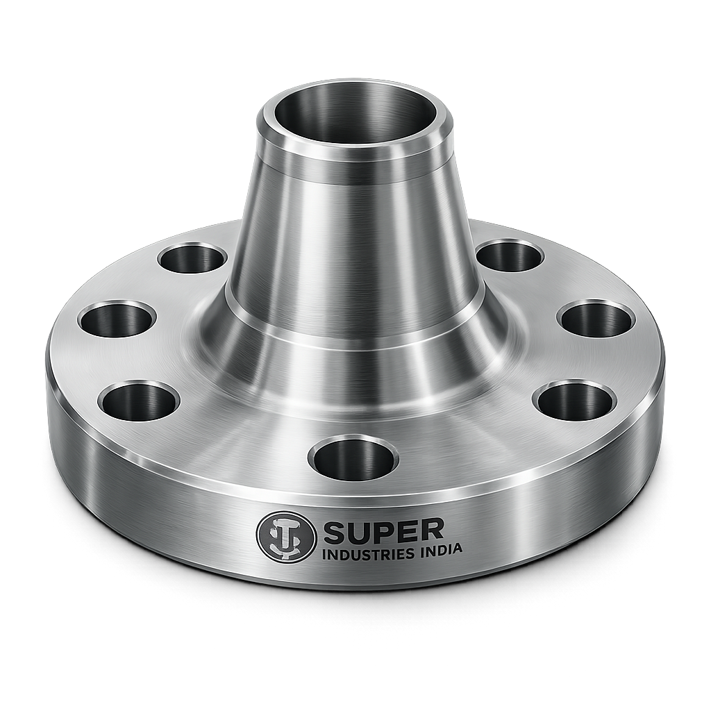
Weld Neck Flanges are deployed in piping systems where structural integrity, pressure containment, and long-term reliability are critical design requirements. These flanges are specifically selected for applications involving high internal pressures, elevated temperatures, cyclic loading conditions, and dynamic mechanical stresses.
Role in High-Pressure Piping Systems
In pressure systems governed by ASME codes, the flange joint represents a potential discontinuity in the pressure boundary. Weld Neck Flanges are engineered to minimize this discontinuity by creating a gradual stress transition between the pipe and the flange through a tapered hub geometry.
This design allows:
- Uniform stress distribution across the weld joint
- Reduction in localized stress concentration
- Enhanced resistance to pressure-induced deformation
- Improved fatigue life under fluctuating loads
In high-pressure services (Class 600 and above), flange joints are subject to:
- Axial tensile loads due to internal pressure
- Radial expansion forces
- Bending stresses from pipeline misalignment
- Thermal expansion and contraction cycles
Weld Neck Flanges are structurally suited to absorb and redistribute these stresses without compromising sealing integrity.
Role in High-Temperature Services
Elevated temperature environments introduce additional challenges:
- Reduction in material yield strength
- Creep deformation over time
- Thermal expansion mismatch between components
The extended hub of Weld Neck Flanges acts as a thermal gradient buffer, allowing gradual heat transfer from the pipe to the flange. This reduces thermal shock and mitigates stress concentration at the weld junction.
Applications include:
- Superheated steam lines in power plants
- High-temperature hydrocarbon processing in refineries
- Heat recovery systems in petrochemical plants
Role in Critical Process Pipelines
Critical service pipelines require:
- Zero leakage tolerance
- High fatigue resistance
- Inspection accessibility
- Compliance with stringent codes and standards
Weld Neck Flanges are preferred in such systems due to:
- Full penetration butt weld connection
- Radiographic inspection capability
- Structural continuity with the pipe
- High reliability under cyclic pressure conditions
Application Sectors
Oil & Gas Industry
Upstream:
- Wellhead assemblies
- High-pressure drilling lines
Midstream:
- Crude oil and gas transmission pipelines
- Compressor station piping
Downstream:
- Refinery process units
- Hydrocracking and reforming systems
Petrochemical Plants
- Chemical reactors
- Process transfer lines
- Corrosive fluid handling systems
Power Generation
- Boiler feedwater systems
- Steam distribution lines
- Turbine inlet piping
LNG Terminals
- Cryogenic piping systems
- High-integrity transfer lines
- Storage and regasification systems
Offshore Platforms
- Subsea pipelines
- Riser systems
- Structural piping exposed to dynamic loads
Hydrogen & Emerging Energy Systems
- High-pressure hydrogen transport
- Electrolyzer connections
- Hydrogen-compatible alloy systems
Design Preference Over Other Flange Types
Comparison with Slip-On Flanges
Slip-On Flanges:
- Fillet welds instead of full penetration welds
- Higher stress concentration at weld toe
- Lower fatigue resistance
- Reduced suitability for high-pressure service
Weld Neck Flanges:
- Butt-welded with full penetration
- Superior stress distribution
- Higher fatigue resistance
- Preferred for cyclic and critical services
Comparison with Threaded Flanges
Threaded Flanges:
- Limited to low-pressure systems
- Not suitable for high-temperature applications
- Risk of leakage through threaded joints
Weld Neck Flanges:
- No threading-induced stress concentration
- Suitable for high pressure and temperature
- Superior sealing integrity
Fatigue Resistance & Structural Integrity
In cyclic service conditions (e.g., pump discharge lines, compressor systems), fatigue failure becomes a governing design factor.
Weld Neck Flanges provide:
- Smooth stress flow from pipe to flange
- Elimination of abrupt geometric discontinuities
- Reduced stress intensity factors
- Increased number of fatigue cycles before failure
This makes them suitable for:
- Pulsating flow systems
- Vibration-prone installations
- Thermal cycling environments
2. Technical Definition
Weld Neck Flanges are defined as:
A butt-welded flange with an extended, tapered hub designed to provide reinforcement and ensure smooth stress transition between the flange and the connected pipe.
Key Structural Features
1. Tapered Hub Geometry
The hub is gradually tapered from the flange thickness to the pipe wall thickness. This geometry ensures:
- Reduced stress concentration
- Uniform load transfer
- Improved fatigue performance
2. Bore Matching
The internal bore of the flange is machined to match the internal diameter of the pipe (based on pipe schedule). This enables:
- Smooth fluid flow
- Elimination of turbulence
- Reduced erosion and pressure drop
3. Full Penetration Butt Weld
The flange is welded to the pipe using a butt weld, typically subjected to:
- Radiographic Testing (RT)
- Ultrasonic Testing (UT)
This ensures:
- Complete fusion across the joint
- Absence of internal defects
- Structural continuity
4. Transition Radius
The junction between the hub and flange face includes a controlled radius to:
- Minimize stress risers
- Improve fatigue life
- Ensure compliance with design codes
Super Industries
Global Manufacturer of Heavy & Custom Engineered Fasteners & Flanges
3. Engineering & Sealing Principle
The performance of Weld Neck Flanges is governed by the interaction of:
- Bolt preload
- Internal pressure
- Gasket compression
- Flange rigidity
Load Transfer Mechanism
When the system is pressurized:
- Internal pressure generates axial force attempting to separate the flange joint
- Bolt preload resists this separation
- Load is transferred from flange to pipe through the welded hub
- Stress is distributed along the tapered hub, reducing peak stresses
Stress Distribution
The tapered hub ensures:
- Gradual transition of bending stresses
- Reduced stress concentration at weld interface
- Improved resistance to combined loading conditions
Gasket Compression Mechanics
The gasket acts as the sealing element between flange faces.
Sealing requires:
- Sufficient bolt preload to compress the gasket
- Maintenance of compression under operating pressure
- Prevention of gasket relaxation
Bolt Preload vs Internal Pressure
- Bolt preload must exceed the separating force generated by internal pressure
- Excess preload can lead to flange rotation or gasket crushing
- Insufficient preload results in leakage
Flange Rotation Behavior
Under load:
- Flanges tend to rotate slightly about the bolt circle
- This rotation reduces gasket compression at the inner diameter
- Proper flange thickness and rigidity minimize rotation
Face Sealing Types
Raised Face (RF)
- Most commonly used configuration
- Gasket seated on raised portion of flange face
- Suitable for moderate to high pressure applications
Characteristics:
- Controlled surface finish (typically 3.2–6.3 µm Ra)
- Compatible with soft gaskets
Ring Type Joint (RTJ)
- Used for high-pressure and high-temperature services
- Metal-to-metal sealing with ring gasket
Characteristics:
- Precision-machined grooves
- High contact stress sealing
- Suitable for Class 600 and above
Surface Finish & Sealing Integrity
Surface roughness directly impacts gasket performance:
- Too smooth → insufficient friction, risk of leakage
- Too rough → gasket damage and uneven sealing
Typical requirements:
- RF faces: serrated finish
- RTJ grooves: fine machined finish with strict tolerances
Leakage Prevention Mechanism
Leakage is prevented through:
- Proper gasket selection
- Adequate bolt preload
- Controlled flange deformation
- Precision-machined sealing surfaces
Failure modes include:
- Gasket blowout
- Bolt relaxation
- Flange distortion
- Surface damage
Weld Neck Flanges mitigate these risks through:
- Structural rigidity
- Welded continuity
- Controlled geometry
4. Pressure & Load Engineering
Weld Neck Flanges are designed according to standardized pressure classes defined in ASME systems.
ASME Pressure Classes
- Class 150
- Class 300
- Class 600
- Class 900
- Class 1500
- Class 2500
Each class corresponds to:
- Maximum allowable pressure at a given temperature
- Defined dimensions and thickness
- Standardized bolt patterns
Internal Pressure Containment
Internal pressure generates:
- Axial force on flange faces
- Hoop stress in pipe
- Radial expansion
Weld Neck Flanges are designed to:
- Withstand internal pressure without yielding
- Maintain sealing under pressure fluctuations
- Prevent joint separation
External Loads
Bending Loads
- Caused by pipe misalignment or external forces
- Transmitted through flange hub
Vibration Loads
- Induced by pumps, compressors, and flow turbulence
- Lead to fatigue failure if not properly managed
Thermal Expansion
- Differential expansion between pipe and flange
- Generates axial and bending stresses
Fatigue Resistance
Weld Neck Flanges provide:
- Reduced stress concentration
- Improved load distribution
- Extended fatigue life
Safety Factors
Design incorporates:
- Material yield strength margins
- Load amplification factors
- Code-based safety limits
Burst Margin Philosophy
- Flanges are designed to withstand pressures significantly higher than operating conditions
- Burst pressure is typically several times the rated pressure
- Ensures safety under abnormal conditions
Dimensional & Design Logic
Dimensional accuracy is critical for interchangeability, sealing, and compliance with international standards.
Key Dimensions
Outside Diameter (OD)
- Determines overall flange size
- Must match standard dimensions
Bore Diameter (ID)
- Matched to pipe internal diameter
- Based on pipe schedule
Hub Thickness & Height
- Governs strength and stress distribution
- Designed based on pressure class
Bolt Circle Diameter (BCD)
- Defines bolt placement
- Ensures uniform load distribution
Bolt Hole Size & Count
- Standardized per pressure class
- Influences joint strength and preload capacity
Geometric Control Parameters
Concentricity
- Bore must align with flange centerline
- Prevents flow disturbance and stress imbalance
Perpendicularity
- Flange face must be perpendicular to axis
- Ensures uniform gasket compression
Flatness
- Critical for sealing performance
- Controlled within tight tolerances
Surface Roughness
- Measured in Ra (µm)
- Directly affects gasket sealing
Design Integration Philosophy
Weld Neck Flanges are not standalone components; they are part of an integrated pressure system.
Their design ensures:
- Compatibility with pipe schedules
- Compliance with ASME dimensional standards
- Structural continuity across the piping system
5. Applicable Standards (ASTM / ASME / DIN / EN / ISO)
Weld Neck Flanges are manufactured and verified against internationally accepted standards to ensure dimensional interchangeability, pressure integrity, and material compliance across global EPC projects.
ASME Standards
ASME B16.5
Primary governing standard for:
- Weld Neck Flanges up to NPS 24
- Pressure Classes: 150 to 2500
Defines:
- Dimensional tolerances
- Pressure-temperature ratings
- Facing types (RF, RTJ)
- Bolt circle and drilling patterns
Applicable in:
- Oil & Gas
- Refineries
- Power plants
- Petrochemical systems
ASME B16.47
Applicable for:
- Large diameter flanges (NPS 26 to NPS 60)
Divided into:
- Series A (MSS SP-44 based)
- Series B (API 605 based)
Defines:
- Larger bolt circle diameters
- Reduced or increased bolt counts based on series
- Structural differences for heavy-duty applications
ASTM Material Standards
Material compliance for Weld Neck Flanges is governed by ASTM specifications, ensuring chemical composition, mechanical properties, and heat treatment requirements.
Common ASTM Specifications
- ASTM A105 — Carbon steel forgings for ambient and high-temperature service
- ASTM A350 LF2 — Low-temperature carbon steel with impact toughness
- ASTM A182 — Alloy and stainless steel forgings
These standards define:
- Chemical composition limits
- Mechanical property requirements
- Heat treatment conditions
- Testing requirements
EN Standards
EN 1092-1
European standard covering:
- Flange dimensions
- Pressure ratings (PN system: PN10 to PN400)
- Facing types and tolerances
Used in:
- European EPC projects
- Cross-border engineering contracts
DIN Standards
Common DIN flange standards include:
- DIN 2527
- DIN 2633 / 2635 (pressure classes PN16, PN40)
Defines:
- Metric-based dimensions
- Pressure ratings in PN system
- Face types and drilling
ISO Standards
ISO standards align international requirements and ensure compatibility between ASME and EN systems.
Used for:
- Global procurement harmonization
- Cross-standard verification
- International project documentation
Standard Mapping Logic
| Standard | System Type | Pressure Format | Application Region |
|---|---|---|---|
| ASME B16.5 | Inch-based | Class | USA, Middle East, Global EPC |
| ASME B16.47 | Inch-based | Class | Large diameter pipelines |
| EN 1092-1 | Metric | PN | Europe |
| DIN | Metric | PN | Germany, EU |
| ISO | Hybrid | PN/Class | International |
Pressure-Temperature Relationship
All standards define allowable pressure as a function of temperature:
- As temperature increases → allowable pressure decreases
- Material grade influences temperature limits
- Design must consider worst-case operating conditions
6. Material & Grade Options
Material selection for Weld Neck Flanges is governed by:
- Pressure rating
- Operating temperature
- Corrosion environment
- Fluid characteristics
- Code compliance
Carbon Steel Grades
ASTM A105
Used for:
- Ambient to moderately high-temperature service
- Non-corrosive environments
Characteristics:
- Good strength
- Cost-effective
- Suitable for hydrocarbon service
ASTM A350 LF2
Used for:
- Low-temperature service
Characteristics:
- Improved notch toughness
- Suitable for sub-zero applications
- Mandatory impact testing (Charpy)
Stainless Steel Grades
ASTM A182 F304
- General corrosion resistance
- Suitable for water, mild chemicals
ASTM A182 F316
- Enhanced corrosion resistance due to molybdenum
- Suitable for marine and chloride environments
Alloy Steel Grades
ASTM A182 F11
- Chromium-molybdenum alloy
- High-temperature strength
ASTM A182 F22
- Higher chromium content than F11
- Improved creep resistance
- Used in power plants and refineries
Duplex & Super Duplex Stainless Steel
Used for:
- Aggressive corrosive environments
- Offshore and marine systems
Characteristics:
- High strength
- Excellent resistance to stress corrosion cracking
- Superior performance in chloride-rich environments
Material Selection Logic
Material is selected based on:
- Design temperature
- Corrosion allowance
- Mechanical load conditions
- Code requirements (ASME, NACE, etc.)
MANDATORY MATERIAL COMPARISON TABLE
| Material Grade | Yield Strength (MPa) | Tensile Strength (MPa) | Temperature Range (°C) | Corrosion Resistance | Typical Industry Use |
|---|---|---|---|---|---|
| ASTM A105 | ~250 | ~485 | -29 to 425 | Low | Oil & Gas, Refineries |
| ASTM A350 LF2 | ~250 | ~485 | -46 to 345 | Low | Low-temp pipelines |
| ASTM A182 F304 | ~205 | ~515 | -196 to 870 | Moderate | Chemical, Water systems |
| ASTM A182 F316 | ~205 | ~515 | -196 to 870 | High | Marine, Chemical |
| ASTM A182 F11 | ~275 | ~485 | Up to 540 | Moderate | Power plants |
| ASTM A182 F22 | ~415 | ~585 | Up to 600 | Moderate | High-temp service |
| Duplex Stainless | ~450 | ~620 | -50 to 300 | Very High | Offshore, Marine |
7. Heat Treatment Information
Heat treatment is applied to Weld Neck Flanges to achieve required mechanical properties, microstructure stability, and compliance with ASTM specifications.
1. Normalizing
Process:
- Heating above critical temperature
- Air cooling
Purpose:
- Refines grain structure
- Improves toughness
- Enhances uniformity
Used for:
- Carbon steel flanges
2. Quenching & Tempering (Q&T)
Process:
- Rapid cooling (quenching)
- Reheating to controlled temperature (tempering)
Purpose:
- Increase strength
- Improve toughness
- Balance hardness and ductility
Used for:
- Alloy steel grades (F11, F22)
3. Solution Annealing
Process:
- Heating to high temperature
- Rapid cooling
Purpose:
- Dissolves carbides
- Restores corrosion resistance
Used for:
- Stainless steel grades (F304, F316)
4. Stress Relieving
Process:
- Heating below transformation temperature
- Controlled cooling
Purpose:
- Reduce residual stresses from forging and machining
- Improve dimensional stability
Hardness Ranges (Typical)
| Material Type | Hardness (HB) |
|---|---|
| Carbon Steel | 120 – 200 |
| Alloy Steel | 150 – 220 |
| Stainless Steel | 140 – 200 |
Grain Structure Impact
Heat treatment controls:
- Grain size
- Phase distribution
- Mechanical strength
Fine grain structure results in:
- Improved fatigue resistance
- Higher impact toughness
Charpy Impact Testing
Applicable for:
- Low-temperature service (A350 LF2)
- Critical applications
Measures:
- Energy absorption during fracture
Ensures:
- Resistance to brittle failure
8. Manufacturing Process
Manufacturing of Weld Neck Flanges follows a controlled sequence to ensure dimensional accuracy, mechanical strength, and compliance with applicable standards.
Step-by-Step Manufacturing Flow
1. Raw Material Inspection
- Verification of material certificates
- Chemical composition analysis
- Visual and dimensional checks
2. Forging
- Open-die or closed-die forging
- Controlled deformation to achieve required shape
Purpose:
- Improve grain flow
- Eliminate internal defects
- Increase strength
3. Rough Machining
- Removal of excess material
- Initial shaping of flange profile
4. CNC Finishing
- Precision machining using CNC equipment
- Achieving tight tolerances
5. Bore Machining
- Machining internal diameter to match pipe schedule
- Ensuring smooth internal surface
6. Hub Profiling
- Tapered hub formation
- Controlled transition geometry
7. Bolt Hole Drilling
- Drilling based on standard bolt circle
- Angular spacing accuracy
8. Facing (RF / RTJ)
- Machining sealing surfaces
- Serrated finish for RF
- Groove machining for RTJ
9. Heat Treatment
- As per material specification
- Controlled temperature cycles
10. Surface Finishing
- Cleaning
- Coating or passivation
11. Final Inspection
- Dimensional verification
- NDT testing
- Documentation review
12. Marking & Traceability
- Heat number
- Material grade
- Size and pressure class
- Manufacturer identification
Ensures:
- Full traceability from raw material to finished product
9. Surface Finish Options
Surface protection and sealing surface finish are critical for both corrosion resistance and gasket performance.
Protective Coatings
Anti-Rust Oil Coating
- Temporary protection during storage and transport
Black Oxide Coating
- Mild corrosion resistance
- Improved surface appearance
Phosphate Coating
- Enhanced corrosion resistance
- Improved paint adhesion
Zinc Plating
- Electrochemical protection
- Suitable for mild environments
Hot-Dip Galvanizing
- Thick zinc layer
- Suitable for outdoor and marine exposure
Passivation (Stainless Steel)
- Removal of free iron
- Enhances corrosion resistance
Surface Roughness (Ra Values)
| Face Type | Typical Ra Value |
|---|---|
| Raised Face (RF) | 3.2 – 6.3 µm |
| Smooth Finish | < 3.2 µm |
| RTJ Groove | Fine machined (tight tolerance) |
RTJ Groove Requirements
- High dimensional accuracy
- Smooth surface finish
- Strict tolerance control
Ensures:
- Proper seating of ring gasket
- Metal-to-metal sealing
A. Technical Dimension Tables (ASME B16.5 Reference)
The following tables represent typical dimensional parameters for Weld Neck Flanges. Final dimensions must always be verified against the applicable revision of ASME standards and project specifications.
Class 150 Weld Neck Flanges (Indicative)
| NPS (in) | Bore (mm) | Flange OD (mm) | Thickness (mm) | BCD (mm) | Bolt Size | No. of Bolts |
|---|---|---|---|---|---|---|
| 1 | 27.3 | 108 | 11 | 79.5 | M12 | 4 |
| 2 | 60.3 | 152 | 13 | 120.5 | M16 | 4 |
| 4 | 114.3 | 229 | 15 | 190.5 | M16 | 8 |
| 6 | 168.3 | 279 | 17 | 241.5 | M20 | 8 |
| 8 | 219.1 | 343 | 19 | 298.5 | M20 | 8 |
| 10 | 273.0 | 406 | 24 | 362.0 | M24 | 12 |
| 12 | 323.9 | 483 | 26 | 431.8 | M24 | 12 |
Class 300 Weld Neck Flanges (Indicative)
| NPS (in) | Bore (mm) | Flange OD (mm) | Thickness (mm) | BCD (mm) | Bolt Size | No. of Bolts |
|---|---|---|---|---|---|---|
| 1 | 27.3 | 117 | 14 | 88.9 | M14 | 4 |
| 2 | 60.3 | 165 | 16 | 127.0 | M16 | 8 |
| 4 | 114.3 | 254 | 19 | 200.0 | M20 | 8 |
| 6 | 168.3 | 318 | 22 | 269.9 | M20 | 12 |
| 8 | 219.1 | 381 | 24 | 330.2 | M24 | 12 |
| 10 | 273.0 | 445 | 29 | 387.4 | M27 | 16 |
| 12 | 323.9 | 521 | 32 | 450.9 | M30 | 16 |
Dimensional Engineering Notes
- Bore size must match pipe internal diameter based on schedule (e.g., SCH 40, SCH 80)
- Bolt circle diameter (BCD) governs load distribution and tightening pattern
- Thickness increases with pressure class to resist flange rotation
- Hub dimensions (not shown above) are critical for stress transition
B. Pressure Rating Table (ASME Conceptual Reference)
Pressure ratings vary with temperature and material group. The table below presents a simplified reference for carbon steel (ASTM A105).
Pressure Class vs Pressure Rating
| Class | Pressure (psi @ 38°C) | Pressure (MPa) | Typical Max Temp (°C) |
|---|---|---|---|
| 150 | 285 | 1.96 | 425 |
| 300 | 740 | 5.10 | 425 |
| 600 | 1480 | 10.20 | 425 |
| 900 | 2220 | 15.30 | 425 |
| 1500 | 3705 | 25.55 | 425 |
| 2500 | 6170 | 42.55 | 425 |
Engineering Interpretation
- Pressure rating decreases as temperature increases
- Material group classification determines allowable limits
- Design must consider worst-case operating temperature
C. Torque Chart
Bolt tightening torque is dependent on:
- Bolt size
- Bolt material grade
- Lubrication condition
- Desired preload
Indicative Torque Values
| Bolt Size | Grade B7 (Nm) | Class 8.8 (Nm) | Class 10.9 (Nm) | Lubricated Reduction (%) |
|---|---|---|---|---|
| M16 | 210 | 180 | 260 | ~20% |
| M20 | 420 | 360 | 520 | ~20% |
| M24 | 720 | 610 | 900 | ~20% |
| M27 | 1050 | 900 | 1350 | ~20% |
| M30 | 1450 | 1250 | 1800 | ~20% |
| M36 | 2500 | 2100 | 3000 | ~20% |
Torque Application Notes
- Apply torque in cross-pattern sequence
- Use calibrated torque wrench or hydraulic tensioner
- Lubrication reduces friction and required torque
- Over-tightening may cause flange distortion or bolt yielding
D. Preload Calculation Guide
Proper preload ensures gasket sealing and joint integrity.
1. Bolt Stress Formula
![\[\sigma = \frac{F}{A}\]](https://superindustriesindia.in/wp-content/ql-cache/quicklatex.com-d820ba2a7649df33c4e35cab55485169_l3.png "Rendered by QuickLaTeX.com")
Where:
- ( \sigma ) = Bolt stress (MPa)
- ( F ) = Axial preload force (N)
- ( A ) = Bolt stress area (mm²)
2. Preload Force Calculation
![\[F = \sigma \times A\]](https://superindustriesindia.in/wp-content/ql-cache/quicklatex.com-25ff6a73f31ac5e92b4f610bfc43346c_l3.png "Rendered by QuickLaTeX.com")
3. Torque Relationship
![\[T = K \cdot F \cdot d\]](https://superindustriesindia.in/wp-content/ql-cache/quicklatex.com-637ae80de10d14a2f4d17cc6dfd9f1fa_l3.png "Rendered by QuickLaTeX.com")
Where:
- ( T ) = Torque (Nm)
- ( K ) = Torque coefficient (typically 0.18–0.25)
- ( d ) = Nominal bolt diameter (m)
4. Axial Force from Internal Pressure
![\[F_p = P \cdot A_g\]](https://superindustriesindia.in/wp-content/ql-cache/quicklatex.com-ae46fa16e7ec79c305ba6aa1355605a9_l3.png "Rendered by QuickLaTeX.com")
Where:
- ( P ) = Internal pressure (MPa)
- ( A_g ) = Effective gasket area (mm²)
5. Sample Engineering Calculation
Given:
- Pressure ( P = 10 , MPa )
- Gasket area ( A_g = 5000 , mm^2 )
Axial force:
![\[F_p = 10 \times 5000 = 50{,}000 \, N\]](https://superindustriesindia.in/wp-content/ql-cache/quicklatex.com-27f6f80f9b8aebca15ef9add01f53c73_l3.png "Rendered by QuickLaTeX.com")
Required preload (with safety factor 2):
![\[F = 100{,}000 \, N\]](https://superindustriesindia.in/wp-content/ql-cache/quicklatex.com-23c5b1805d1c0d16a7d81acf6e2afeb6_l3.png "Rendered by QuickLaTeX.com")
For M20 bolt (area ≈ 245 mm²):
![\[\sigma = \frac{100000}{245} \approx 408 \, \text{MPa}\]](https://superindustriesindia.in/wp-content/ql-cache/quicklatex.com-349fcf5931b596f4a03f1f39af3f8b9d_l3.png "Rendered by QuickLaTeX.com")
Torque (K = 0.2, d = 0.02 m):
![\[T = 0.2 \times 100000 \times 0.02 = 400 \, \text{Nm}\]](https://superindustriesindia.in/wp-content/ql-cache/quicklatex.com-e44a9496a624a31479386f7e9c6d9762_l3.png "Rendered by QuickLaTeX.com")
6. Safety Factor Logic
- Minimum preload ≥ 1.5 to 2 times internal pressure force
- Prevents joint separation
- Maintains gasket compression under dynamic loads
E. Yield Strength Chart (Text Explanation)
Yield strength defines the maximum stress a material can withstand without permanent deformation.
Engineering implications:
- Higher yield strength → higher allowable preload
- Determines bolt tightening limits
- Influences flange thickness design
Typical hierarchy:
- Carbon Steel < Stainless Steel < Alloy Steel < Duplex
Design must ensure:
- Bolt stress < yield strength
- Flange stress within allowable limits
F. Mechanical Property Table
| Material Grade | Yield Strength (MPa) | Tensile Strength (MPa) | Elongation (%) | Hardness (HB) | Impact Value (J) |
|---|---|---|---|---|---|
| ASTM A105 | 250 | 485 | 20 | 120–200 | 27 |
| ASTM A350 LF2 | 250 | 485 | 22 | 120–200 | 40+ |
| A182 F304 | 205 | 515 | 30 | 140–200 | 60+ |
| A182 F316 | 205 | 515 | 30 | 140–200 | 60+ |
| A182 F11 | 275 | 485 | 20 | 150–220 | 27 |
| A182 F22 | 415 | 585 | 18 | 160–220 | 27 |
G. Corrosion Resistance Comparison Table
| Material | Marine | Acidic | Hydrocarbon | High Humidity |
|---|---|---|---|---|
| Carbon Steel | Low | Low | Moderate | Low |
| SS304 | Moderate | Moderate | High | High |
| SS316 | High | High | High | High |
| Alloy Steel | Moderate | Low | High | Moderate |
| Duplex Steel | Very High | High | High | Very High |
10. Inspection & Quality Control Methods
Inspection ensures compliance with standards, material integrity, and dimensional accuracy.
1. Positive Material Identification (PMI)
- Verifies chemical composition
- Ensures correct material grade
2. Ultrasonic Testing (UT)
- Detects internal defects
- Ensures forging integrity
3. Magnetic Particle Inspection (MPI)
- Detects surface and near-surface cracks
- Applicable for ferromagnetic materials
4. Dye Penetrant Inspection (DPI)
- Detects surface defects
- Used for stainless and non-magnetic materials
5. Hydrostatic Testing (If Applicable)
- Confirms pressure integrity
- Detects leakage
6. Dimensional Inspection
- OD, ID, thickness, BCD
- Tolerance verification per ASME
7. Hardness Testing
- Confirms heat treatment effectiveness
- Ensures compliance with material standards
8. Third-Party Inspection (TPI)
Conducted by:
- Independent inspection agencies
- Client-appointed inspectors
Includes:
- Stage-wise inspection
- Witness testing
- Documentation verification
9. Certification
EN 10204 3.1
- Manufacturer test certificate
- Confirms compliance with order
EN 10204 3.2
- Third-party verified certificate
- Required for critical applications
Quality Documentation Includes
- Material Test Certificates (MTC)
- Heat treatment records
- NDT reports
- Dimensional reports
- Compliance certificates
11. Industries Served
Weld Neck Flanges are deployed in sectors where piping systems operate under high pressure, elevated temperature, corrosive environments, and cyclic mechanical loading. Selection is typically governed by ASME design requirements, process conditions, and inspection criticality.
Oil & Gas Industry
Upstream (Exploration & Production)
Applications:
- Wellhead assemblies
- High-pressure choke and kill lines
- Drilling mud circulation systems
Engineering Requirements:
- High-pressure containment (Class 1500–2500)
- Resistance to cyclic loading from drilling operations
- Compatibility with sour service (where applicable)
Material Selection:
- ASTM A105 for general service
- Low-alloy or duplex grades for corrosive environments
Midstream (Transportation & Storage)
Applications:
- Cross-country pipelines
- Compressor station piping
- Metering and custody transfer systems
Engineering Requirements:
- Long-term fatigue resistance
- Structural reliability over extended pipeline lengths
- Resistance to vibration and pressure fluctuations
Weld Neck Flanges are preferred due to:
- Smooth stress transition
- Welded structural continuity
- Reduced maintenance requirements
Downstream (Refining & Processing)
Applications:
- Distillation units
- Hydrocracking and reforming units
- High-temperature process piping
Engineering Requirements:
- Resistance to high temperature and pressure
- Compatibility with hydrocarbon media
- Compliance with refinery inspection protocols
Petrochemical Industry
Applications:
- Reactor inlet and outlet connections
- Chemical transfer lines
- Corrosive fluid handling systems
Engineering Considerations:
- Chemical compatibility of material
- Corrosion resistance (SS316, Duplex)
- Leak-tight sealing under process conditions
Refineries
Applications:
- Process piping networks
- High-pressure separator systems
- Furnace and heater connections
Requirements:
- High reliability under continuous operation
- Resistance to thermal cycling
- Inspection accessibility (RT/UT welds)
Power Generation
Thermal Power Plants
Applications:
- Boiler feedwater systems
- Main steam lines
- Turbine inlet piping
Engineering Requirements:
- High-temperature creep resistance
- Pressure containment under superheated steam conditions
Materials:
- Alloy steels (ASTM A182 F11, F22)
Nuclear Power
Requirements:
- Strict compliance with nuclear-grade specifications
- Full traceability
- Enhanced inspection protocols
LNG Terminals
Applications:
- Cryogenic pipelines
- Liquefaction and regasification systems
Engineering Requirements:
- Low-temperature toughness
- Resistance to brittle fracture
Materials:
- ASTM A350 LF2
- Austenitic stainless steels
Hydrogen Systems
Applications:
- Hydrogen transport lines
- Electrolyzer piping
Engineering Requirements:
- Resistance to hydrogen embrittlement
- Leak-tight joints under high pressure
Materials:
- Austenitic stainless steel
- Duplex grades
Offshore Platforms
Applications:
- Subsea pipelines
- Riser systems
- Deck piping exposed to marine environment
Engineering Requirements:
- Resistance to chloride-induced corrosion
- High fatigue resistance under wave-induced loading
- Structural reliability under dynamic conditions
Heavy Engineering & Infrastructure
Applications:
- Process plants
- Fertilizer plants
- Steel and metallurgical industries
Requirements:
- High load-bearing capacity
- Resistance to industrial environments
12. Export Capability & Global Supply
Super Industries manufactures Weld Neck Flanges for global EPC contractors and project-based procurement across multiple regions.
Export Regions
United States
- Compliance with ASME B16.5 and ASTM standards
- Documentation aligned with EPC contractor requirements
Europe
- EN 1092-1 and DIN standard compliance
- Metric dimensional compatibility
Middle East
- Oil & gas project supply
- High-pressure and high-temperature service requirements
Southeast Asia
- Petrochemical and infrastructure projects
- Mixed standard requirements (ASME + EN)
Export Packaging Standards
Packaging is designed to prevent mechanical damage, corrosion, and dimensional distortion during transit.
Methods include:
- Wooden crates (ISPM 15 compliant)
- Palletized packaging with strapping
- Protective end covers for flange faces
- Moisture barrier wrapping
Documentation Package
Each shipment is supported by a structured documentation set:
- Material Test Certificates (MTC)
- Heat treatment records
- Non-destructive testing (NDT) reports
- Dimensional inspection reports
- Compliance certificates (ASME / EN)
- Packing list and traceability records
Project Logistics Capability
Supply capability includes:
- Bulk order execution for EPC projects
- Lot-wise traceability
- Stage inspection coordination
- Integration with third-party inspection agencies
Logistics considerations:
- Shipment consolidation
- Export compliance documentation
- Coordination with project timelines
13. Procurement & Installation View
Weld Neck Flanges are specified and installed based on engineering drawings, piping class specifications, and welding procedures.
Butt Welding Procedure
- Weld type: Full penetration butt weld
- Welding standards: ASME Section IX
Key steps:
- Edge preparation (beveling)
- Alignment and fit-up
- Root pass welding
- Fill and cap passes
- Post-weld inspection
Weld Inspection
Inspection methods include:
- Radiographic Testing (RT)
- Ultrasonic Testing (UT)
Objective:
- Detect internal defects
- Verify weld integrity
Bolt Tightening Procedure
Cross Tightening Pattern
- Bolts are tightened in a star or cross sequence
- Ensures uniform gasket compression
Multi-Stage Tightening
Typical sequence:
- 30% of final torque
- 60% of final torque
- 100% of final torque
Gasket Installation
- Selection based on pressure class and service
- Proper centering between flange faces
- Avoid damage during installation
Re-Torque Requirements
- Re-tightening after initial pressurization
- Compensates for gasket relaxation and bolt settling
Storage Practices
- Store in dry, covered environment
- Protect flange faces with covers
- Avoid direct ground contact
- Maintain traceability markings
14. Custom Engineering Capabilities
Super Industries supports project-specific manufacturing requirements for Weld Neck Flanges.
Customization Scope
Non-Standard Sizes
- Beyond ASME B16.5 and B16.47 ranges
- Project-specific dimensions
Special Bore Matching
- Customized internal diameter
- Integration with non-standard pipe schedules
Custom Hub Dimensions
- Modified hub thickness and length
- Designed for specific stress conditions
RTJ Groove Modifications
- Custom groove profiles
- Project-specific sealing requirements
Project-Specific Markings
- Client identification
- Heat number traceability
- Inspection stamps
Coating Customization
- Project-specified coatings
- Corrosion protection based on environment
Engineering Conclusion
Weld Neck Flanges form a critical component in pressure piping systems where joint integrity, fatigue resistance, and long-term reliability are required.
Their design characteristics — including a tapered hub, full penetration weld, and standardized dimensional control — enable:
- Uniform stress distribution
- High resistance to cyclic loading
- Reliable sealing under pressure and temperature variations
Compliance with ASME, ASTM, EN, and DIN standards ensures:
- Global interchangeability
- Code-compliant performance
- Suitability for EPC project evaluation
From a procurement and engineering perspective, Weld Neck Flanges are selected for:
- High-pressure applications
- High-temperature service
- Critical process systems requiring inspection and traceability
Super Industries manufactures Weld Neck Flanges in alignment with:
- International pressure-system standards
- Controlled manufacturing processes
- Documented inspection and testing protocols
The resulting product is suitable for integration into:
- Oil & gas infrastructure
- Power generation systems
- Petrochemical processing units
- LNG and hydrogen applications
This document provides a structured technical reference intended for:
- EPC contractors
- Piping engineers
- Inspection agencies
- Global procurement teams
It reflects adherence to engineering design principles, material science requirements, and international compliance frameworks necessary for pressure system components.