
SERRATED FLANGES
Super Industries
“Global Manufacturer of Heavy & Custom Engineered Fasteners for Oil & Gas, Power & EPC Contractors.”
1. Industry Context & System Relevance
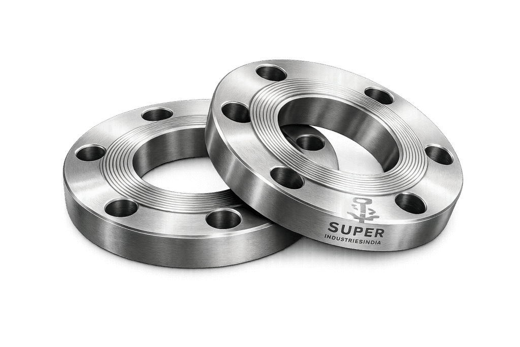
Role of Serrated Flanges in Pressure Systems
Serrated flange joints represent one of the most critical potential leakage points. While pipe, fittings, and valves are typically pressure-rated components with defined wall thickness, the flange joint relies on a combination of mechanical preload and surface interaction to achieve sealing.
Serrated Flanges are used in:
- Refineries & Petrochemical Plants
- Upstream and Midstream Oil & Gas Pipelines
- Power Generation Units (Thermal, Nuclear, Combined Cycle)
- LNG Liquefaction and Regasification Terminals
- Chemical Processing Units
- Offshore Platforms and Subsea Modules
These environments impose:
- High internal pressures
- Thermal cycling
- Corrosive media exposure
- Dynamic loading and vibration
Under such conditions, flange face finish becomes a deterministic factor in joint reliability.
Function in Bolted Flange Joints
A bolted flange joint consists of:
- Two mating flanges
- A gasket
- Bolting system (studs, nuts, washers)
The sealing is achieved by:
- Applying bolt preload
- Compressing the gasket between flange faces
- Generating sufficient contact stress to prevent fluid escape
Serrated flange faces directly influence:
- Gasket seating behavior
- Frictional resistance to gasket movement
- Load distribution across sealing surface
Why Serrated Flange Faces Are Used
Smooth flange faces provide limited frictional interaction with gasket materials, particularly under high-pressure service. This may result in:
- Gasket slippage
- Uneven compression
- Loss of sealing stress
- Blowout under pressure fluctuations
Serrated Flanges introduce controlled surface roughness, which:
- Improves mechanical interlocking between gasket and flange
- Enhances sealing reliability
- Increases resistance to gasket extrusion and blowout
- Stabilizes gasket under cyclic loads
Smooth Face vs Serrated Face Sealing Performance
| Parameter | Smooth Face Flange | Serrated Flange |
|---|---|---|
| Gasket Grip | Low | High |
| Friction Coefficient | Lower | Controlled & Higher |
| Sealing Reliability | Moderate | High |
| Blowout Resistance | Limited | Improved |
| Gasket Stability | Prone to movement | Mechanically restrained |
| Load Distribution | Less uniform | Enhanced distribution |
Engineering Interpretation:
Serrations create micro-contact points that penetrate slightly into the gasket surface, producing a more stable and predictable sealing interface.
Importance in High-Pressure and High-Temperature Joints
In elevated service conditions:
- Gaskets experience creep relaxation
- Bolts lose preload due to thermal expansion differences
- Flanges may undergo rotation and deformation
Serrated surfaces help compensate by:
- Maintaining contact stress through mechanical anchoring
- Reducing dependency on purely elastic gasket behavior
- Supporting long-term sealing under load relaxation
Super Industries
Global Manufacturer of Heavy & Custom Engineered Fasteners & Flanges
2. Technical Definition of Serrated Flanges
Engineering Definition
Serrated Flanges are pressure-retaining flanges with machined surface finishes consisting of controlled concentric or spiral grooves on the sealing face, designed to enhance gasket sealing performance under bolted preload conditions.
Structural Characteristics
A serrated flange includes:
- Flange body (forged or rolled)
- Bolt holes (precision drilled)
- Sealing face (RF, FF, or RTJ)
- Machined serration profile on contact surface
Types of Serrated Flange Faces
Raised Face (RF) Serrated Finish
- Most commonly used configuration
- Serrations applied on a raised portion of flange face
- Standard height per ASME:
- Class 150–300: 1.6 mm (1/16″)
- Class 400 and above: 6.4 mm (1/4″)
Function:
- Concentrates gasket load within defined sealing zone
- Improves gasket compression efficiency
Flat Face (FF) Serrated Finish
- Entire flange face is in contact
- Serrations applied across full face
Application:
- Low-pressure systems
- Cast iron or non-metallic flange connections
- Situations where bending stress must be minimized
Ring Type Joint (RTJ) vs Serrated RF
| Feature | Serrated RF | RTJ |
|---|---|---|
| Sealing Method | Gasket compression | Metal-to-metal ring |
| Surface Finish | Serrated | Smooth precision groove |
| Pressure Range | Medium to High | High to Very High |
| Reusability | Limited (depends on gasket) | Ring replaced each use |
| Installation Complexity | Moderate | High |
Engineering Note:
RTJ flanges rely on plastic deformation of a metal ring, whereas serrated RF flanges depend on surface roughness-controlled gasket interaction.
Stock Finish vs Phonographic Serration
Stock Finish (Standard Serration)
- Spiral serrations generated via lathe machining
- Roughness range:
- 125 to 250 AARH (3.2 to 6.3 µm Ra)
- Continuous spiral groove from center outward
Phonographic Serration (Spiral Finish)
- Similar to record grooves
- Produced using controlled feed rate on lathe
Characteristics:
- Provides continuous sealing path
- Preferred for soft gasket materials
Concentric Serrations
- Independent circular grooves
- No continuous spiral path
Application:
- Used where leakage paths must be minimized
- Often preferred for critical sealing applications
3. Engineering & Sealing Principle
Gasket Compression Mechanics
When bolts are tightened:
- Tensile force is induced in bolts
- Compressive force is transferred to gasket
- Gasket deforms to fill flange surface irregularities
The effectiveness of sealing depends on:
- Achieved gasket stress
- Surface interaction between flange and gasket
Serration Penetration Mechanism
Serrated flanges function by:
- Creating localized high-pressure contact points
- Allowing serrations to slightly embed into gasket surface
- Increasing frictional resistance against lateral movement
This produces:
- Improved sealing under low bolt preload
- Resistance to blowout under internal pressure
Load Distribution Across Flange Face
In a smooth face:
- Load distribution is less controlled
- Micro-gaps may exist
In a serrated face:
- Load is distributed through multiple contact ridges
- Stress concentration enhances sealing
Result:
More uniform and predictable gasket compression.
Micro-Sealing Theory
Sealing occurs at microscopic level:
- Gasket material flows into serration valleys
- Peaks penetrate gasket surface
- Micro voids are eliminated
This creates:
- Multiple sealing barriers
- Reduced leakage pathways
Surface Roughness (Ra) vs Sealing Performance
| Surface Roughness | Effect |
|---|---|
| Too Smooth (< 1.6 µm) | Poor gasket grip |
| Optimal (3.2–6.3 µm) | Balanced sealing & durability |
| Too Rough (> 6.3 µm) | Gasket damage risk |
Engineering Control:
Maintaining controlled roughness is essential to avoid:
- Gasket tearing
- Insufficient sealing stress
- Excessive embedment
Spiral vs Concentric Serration Behavior
| Feature | Spiral Serration | Concentric Serration |
|---|---|---|
| Leakage Path | Continuous path possible | Interrupted paths |
| Gasket Compatibility | Soft gaskets | Semi-metallic gaskets |
| Manufacturing Ease | Easier | More controlled machining |
| Sealing Performance | Standard | Enhanced in critical services |
Blowout Resistance Improvement
Blowout occurs when:
- Internal pressure exceeds gasket retention force
Serrations improve resistance by:
- Increasing frictional retention
- Anchoring gasket material
- Reducing lateral displacement
Bolt Preload vs Gasket Stress Relationship
The sealing mechanism depends on:
- Bolt preload → generates gasket seating stress
- Internal pressure → tends to separate flange
To maintain seal:
Gasket Stress ≥ Internal Pressure-Induced Separation Force
Serrated flanges help maintain this relationship by:
- Enhancing effective contact stress
- Reducing dependence on high bolt loads
Leakage Prevention Through Controlled Surface Finish
Leakage occurs when:
- Micro-channels exist between flange and gasket
Controlled serration ensures:
- Channels are interrupted
- Gasket fills voids effectively
- Fluid path is blocked
Engineering Interpretation
Serrated flanges are not merely surface-finished components; they are:
- Precision-engineered sealing interfaces
- Designed to control:
- Contact stress
- Frictional behavior
- Gasket deformation
Their effectiveness depends on:
- Surface finish accuracy
- Bolt preload control
- Gasket compatibility
4. Applicable Standards (ASTM / ASME / DIN / ISO)
Standards Framework for Serrated Flanges
The design, manufacture, inspection, and application of Serrated Flanges are governed by a combination of dimensional, material, and surface finish standards. These standards ensure interchangeability, pressure integrity, and sealing performance across global EPC projects.
ASME Standards
ASME B16.5
Applies to:
- NPS ½” to 24″
- Pressure Classes: 150 to 2500
Defines:
- Flange dimensions (OD, ID, thickness)
- Bolt circle and hole patterns
- Raised Face (RF) geometry
- Pressure-temperature ratings
Relevance to Serrated Flanges:
- Governs flange geometry on which serrations are applied
- Ensures compatibility with gaskets and bolting systems
- Specifies raised face height affecting gasket compression
ASME B16.47 – Large Diameter Flanges
Applies to:
- NPS 26″ to 60″
- Series A (MSS SP-44) and Series B (API 605)
Defines:
- Large diameter flange dimensions
- Bolt patterns and load distribution
- Structural rigidity requirements
Engineering Relevance:
Large-diameter Serrated Flanges require:
- Controlled serration uniformity across wider surfaces
- Consideration of flange rotation under bolt load
MSS Standard
MSS SP-6 – Standard Finishes for Contact Faces
Critical standard for serration control.
Defines:
- Surface finish types
- Roughness limits
- Machining requirements
Specified Stock Finish:
- 125–250 AARH (Arithmetic Average Roughness Height)
- Equivalent to approximately 3.2–6.3 µm Ra
Importance:
- Directly influences gasket seating performance
- Standardizes sealing interface across manufacturers
ASTM Material Standards
ASTM standards define:
- Chemical composition
- Mechanical properties
- Heat treatment conditions
Relevant material standards include:
- ASTM A105 (carbon steel forgings)
- ASTM A350 LF2 (low-temperature carbon steel)
- ASTM A182 (alloy and stainless steels)
DIN EN Standards
DIN EN 1092-1
Defines:
- Metric flange dimensions
- PN pressure ratings (PN10 to PN400)
- Face types including RF and FF
Relevance:
- Used in European EPC projects
- Requires compatibility with EN gasket standards
ISO Standards
ISO flange standards align with:
- Global dimensional compatibility
- International procurement specifications
Examples:
- ISO 7005 (metal flanges)
- ISO surface finish equivalence to MSS SP-6
Standards Mapping to Engineering Parameters
| Parameter | Governing Standard |
|---|---|
| Dimensions | ASME B16.5 / B16.47 / DIN EN 1092 |
| Pressure Rating | ASME B16.5 / EN 1092 |
| Surface Finish | MSS SP-6 |
| Material | ASTM Standards |
| Inspection | ASTM / ASME / EN |
5. Material & Grade Options
Material Selection Philosophy
Material selection for Serrated Flanges is based on:
- Operating pressure and temperature
- Corrosive environment
- Mechanical loading conditions
- Compatibility with mating components
Carbon Steel Grades
ASTM A105
- Standard forging material for ambient and elevated temperatures
- Suitable for oil & gas, refineries, and general industrial piping
ASTM A350 LF2
- Designed for low-temperature service
- Improved notch toughness
- Used in cryogenic and sub-zero applications
Stainless Steel Grades
ASTM A182 F304
- Austenitic stainless steel
- Good corrosion resistance
- Suitable for chemical and water systems
ASTM A182 F316
- Molybdenum-bearing stainless steel
- Enhanced resistance to chlorides and acids
- Preferred for marine and chemical environments
Alloy Steel Grades
ASTM A182 F11
- Chromium-molybdenum alloy
- Suitable for moderate high-temperature service
ASTM A182 F22
- Higher chromium content
- Used in high-pressure, high-temperature systems such as power plants
Duplex & Super Duplex Stainless Steel
- Dual-phase microstructure
- High strength and corrosion resistance
- Resistant to stress corrosion cracking
Applications:
- Offshore platforms
- Seawater systems
- Aggressive chemical environments
Material Comparison Table
| Grade | Yield Strength (MPa) | Tensile Strength (MPa) | Temperature Range | Corrosion Resistance | Typical Application |
|---|---|---|---|---|---|
| ASTM A105 | ~250 | 485–620 | -29°C to 425°C | Moderate | Oil & gas piping |
| ASTM A350 LF2 | ~250 | 485–620 | -46°C to 345°C | Moderate | Low-temperature service |
| A182 F304 | ~205 | 515–720 | -196°C to 870°C | Good | Chemical plants |
| A182 F316 | ~205 | 515–720 | -196°C to 870°C | High | Marine, chemical |
| A182 F11 | ~275 | 485–620 | Up to 540°C | Moderate | Power plants |
| A182 F22 | ~415 | 585–760 | Up to 600°C | Moderate | High-pressure systems |
| Duplex SS | ~450 | 620–880 | -50°C to 300°C | Very High | Offshore, seawater |
Engineering Considerations in Material Selection
- Higher strength materials reduce flange thickness requirements
- Corrosion-resistant alloys extend service life
- Thermal expansion compatibility must be maintained with piping
6. Heat Treatment Information
Purpose of Heat Treatment
Heat treatment ensures:
- Uniform microstructure
- Mechanical property consistency
- Stress relief after forging and machining
Normalizing
Process:
- Heating above critical temperature
- Air cooling
Effect:
- Grain refinement
- Improved toughness
- Uniform structure
Used for:
- Carbon steel flanges (A105)
Quenching and Tempering (Q&T)
Process:
- Rapid cooling (quenching)
- Controlled reheating (tempering)
Effect:
- Increased strength
- Improved hardness
- Controlled ductility
Used for:
- Alloy steels (F11, F22)
Solution Annealing
Used for:
- Stainless steels
Process:
- Heating to high temperature
- Rapid cooling
Effect:
- Dissolves carbides
- Restores corrosion resistance
Stress Relieving
Purpose:
- Remove residual stresses from machining and forging
Effect:
- Dimensional stability
- Reduced distortion during service
Mechanical Property Stabilization
Heat treatment ensures:
- Consistent yield strength
- Predictable tensile behavior
- Resistance to brittle fracture
Hardness Ranges
Typical hardness:
- Carbon steel: 120–187 HB
- Alloy steel: 150–220 HB
- Stainless steel: 140–200 HB
Charpy Impact Testing
Conducted for:
- Low-temperature applications
Measures:
- Material toughness
- Resistance to brittle fracture
Standards:
- ASTM A370
7. Manufacturing Process
Raw Material Inspection
- Chemical composition verification
- Ultrasonic testing for internal defects
- Mill test certificate validation
Forging / Ring Rolling
- Open-die forging or rolled rings
- Grain flow aligned with flange geometry
Importance:
- Enhances mechanical strength
- Reduces internal defects
CNC Machining
Operations include:
- Turning of OD and ID
- Facing operations
- Bore machining
Control Parameters:
- Dimensional tolerances
- Surface finish
Serration Machining (Critical Step)
Performed using:
- Lathe-based facing tools
Controlled parameters:
- Feed rate
- Tool geometry
- Depth of cut
Objective:
- Achieve required roughness (Ra)
- Maintain uniform serration pitch
Drilling
- Bolt holes drilled using CNC machines
- Ensures alignment with bolt circle
Heat Treatment
- Applied as per material specification
- Controlled furnace conditions
Surface Finishing
- Removal of machining marks
- Anti-corrosion coating (if specified)
Final Inspection
- Dimensional verification
- Surface roughness measurement
- Visual inspection
Marking & Traceability
Includes:
- Material grade
- Heat number
- Pressure class
- Manufacturer identification
Ensures:
- Full traceability for EPC projects
Surface Finish – Critical Engineering Requirement
Stock Finish Specification
Standard serrated finish:
- 125–250 AARH
- 3.2–6.3 µm Ra
Generated via:
- Continuous spiral machining
Types of Serrated Finishes
Spiral Serrated Finish
- Continuous groove
- Common for RF flanges
Concentric Serrations
- Discrete circular grooves
- Used for critical sealing
Effect on Gasket Seating
| Surface Condition | Effect |
|---|---|
| Smooth | Poor grip |
| Controlled Serration | Optimal sealing |
| Excessively Rough | Gasket damage |
Acceptable Roughness Ranges
- Soft gaskets: 3.2–6.3 µm Ra
- Metallic gaskets: lower Ra preferred
- Graphite gaskets: moderate serration required
Inspection Methods
Surface roughness measured using:
- Stylus profilometer
- Optical surface measurement tools
Parameters checked:
- Ra (average roughness)
- Rz (peak-to-valley height)
Engineering Control Requirements
- Uniform serration across entire face
- No radial scratches or discontinuities
- Controlled pitch and depth
8. Flange Dimension Tables (ASME Reference Data)
The following tables represent typical dimensional logic for Serrated Flanges in accordance with ASME B16.5. Values shown are indicative for engineering reference; project-specific drawings govern final supply.
Class 150 – Raised Face Serrated Flanges
| NPS (in) | OD (mm) | ID (mm) | Thickness (mm) | Bolt Circle (mm) | No. of Bolts | Bolt Size |
|---|---|---|---|---|---|---|
| 1″ | 108 | 27 | 14 | 79 | 4 | M14 |
| 2″ | 152 | 53 | 16 | 121 | 4 | M16 |
| 4″ | 229 | 102 | 19 | 191 | 8 | M16 |
| 6″ | 279 | 154 | 21 | 241 | 8 | M20 |
| 8″ | 343 | 203 | 24 | 298 | 8 | M20 |
| 10″ | 406 | 254 | 26 | 362 | 12 | M20 |
Class 300 – Raised Face Serrated Flanges
| NPS (in) | OD (mm) | ID (mm) | Thickness (mm) | Bolt Circle (mm) | No. of Bolts | Bolt Size |
|---|---|---|---|---|---|---|
| 1″ | 124 | 27 | 18 | 89 | 4 | M16 |
| 2″ | 165 | 53 | 20 | 127 | 8 | M16 |
| 4″ | 254 | 102 | 24 | 200 | 8 | M20 |
| 6″ | 318 | 154 | 28 | 270 | 12 | M20 |
| 8″ | 381 | 203 | 32 | 330 | 12 | M24 |
| 10″ | 445 | 254 | 35 | 387 | 16 | M24 |
Dimensional Engineering Interpretation
- Increase in pressure class results in:
- Higher flange thickness
- Increased bolt quantity and diameter
- Larger bolt circle diameter
- This ensures:
- Higher bolt preload capacity
- Reduced flange rotation
- Improved gasket stress retention
9. Pressure Rating vs Temperature
Pressure rating depends on material group and temperature.
ASME Pressure-Temperature Relationship (Carbon Steel)
| Temperature (°C) | Class 150 (bar) | Class 300 (bar) | Class 600 (bar) | Class 900 (bar) |
|---|---|---|---|---|
| 38°C | 19.6 | 51.1 | 102.1 | 153.2 |
| 100°C | 17.7 | 46.0 | 92.0 | 138.0 |
| 200°C | 15.2 | 39.5 | 79.0 | 118.5 |
| 300°C | 13.3 | 34.6 | 69.2 | 103.8 |
| 400°C | 11.8 | 30.7 | 61.4 | 92.1 |
Engineering Considerations
- As temperature increases:
- Allowable stress decreases
- Pressure rating reduces
- Serrated flange performance depends on:
- Maintaining gasket stress despite thermal expansion
- Controlling bolt relaxation
Torque Chart
Torque values are indicative for achieving required preload using standard bolting materials.
Torque Values for ASTM A193 B7 Stud Bolts
| Bolt Size | Torque (Nm) – Dry | Torque (Nm) – Lubricated |
|---|---|---|
| M16 | 210 | 160 |
| M20 | 410 | 310 |
| M24 | 710 | 530 |
| M27 | 1050 | 790 |
| M30 | 1450 | 1100 |
| M36 | 2500 | 1850 |
Torque Values for Property Class 8.8
| Bolt Size | Torque (Nm) – Dry | Torque (Nm) – Lubricated |
|---|---|---|
| M16 | 190 | 140 |
| M20 | 370 | 280 |
| M24 | 640 | 480 |
| M30 | 1300 | 980 |
Engineering Interpretation
- Lubrication reduces friction → lower torque required
- Torque must be controlled to:
- Prevent under-tightening (leakage)
- Avoid over-tightening (bolt yielding, flange distortion)
10. Preload & Gasket Stress Calculation Guide
Bolt Load Equation
![\[F = \frac{T}{K \cdot d}\]](https://superindustriesindia.in/wp-content/ql-cache/quicklatex.com-047c3812ff26cb229181955bd579e870_l3.png "Rendered by QuickLaTeX.com")
Where:
- ( F ) = Bolt preload (N)
- ( T ) = Applied torque (Nm)
- ( K ) = Torque coefficient (typically 0.18–0.25)
- ( d ) = Nominal bolt diameter (m)
Gasket Seating Stress
![\[\sigma_g = \frac{F}{A_g}\]](https://superindustriesindia.in/wp-content/ql-cache/quicklatex.com-b1cf8eb66da040ed5d69c2b824f63219_l3.png "Rendered by QuickLaTeX.com")
Where:
- ( \sigma_g ) = Gasket stress (MPa)
- ( F ) = Total bolt load
- ( A_g ) = Effective gasket area
Flange Separation Force
![\[F_s = P \cdot A_i\]](https://superindustriesindia.in/wp-content/ql-cache/quicklatex.com-d9eda6f681444eee8c08554d41f01b78_l3.png "Rendered by QuickLaTeX.com")
Where:
- ( F_s ) = Separation force
- ( P ) = Internal pressure
- ( A_i ) = Internal pipe area
Sample Calculation
Given:
- Torque = 500 Nm
- Bolt diameter = 20 mm (0.02 m)
- K = 0.2
Bolt Load:
![\[F = \frac{500}{0.2 \times 0.02} = 125{,}000 \, \text{N}\]](https://superindustriesindia.in/wp-content/ql-cache/quicklatex.com-38bad7aab3c4edf90cd7b8fad2ca89b3_l3.png "Rendered by QuickLaTeX.com")
If:
- Gasket area = 0.01 m²
Gasket Stress:
![\[T_{total} = T_{preload} + T_{prevailing}\]](https://superindustriesindia.in/wp-content/ql-cache/quicklatex.com-4362f3fa7efe2140f24e78e83021f27a_l3.png "Rendered by QuickLaTeX.com")
Engineering Interpretation
For sealing integrity:
- Gasket seating stress must exceed:
- Minimum seating stress
- Internal pressure separation effect
Serrated flanges assist by:
- Increasing effective sealing through surface interaction
- Reducing required preload for same sealing performance
Mechanical Properties Table
| Material | Yield Strength (MPa) | Tensile Strength (MPa) | Hardness (HB) | Impact (J) |
|---|---|---|---|---|
| A105 | 250 | 485–620 | 120–187 | ≥27 |
| LF2 | 250 | 485–620 | 120–187 | ≥40 |
| F304 | 205 | 515–720 | 140–200 | ≥60 |
| F316 | 205 | 515–720 | 140–200 | ≥60 |
| F22 | 415 | 585–760 | 150–220 | ≥27 |
Corrosion Resistance Table
| Material | Marine | Acidic | Hydrocarbon | Humidity |
|---|---|---|---|---|
| A105 | Low | Low | Good | Moderate |
| LF2 | Low | Low | Good | Moderate |
| F304 | Moderate | Moderate | Good | High |
| F316 | High | High | Excellent | High |
| Duplex SS | Very High | High | Excellent | Very High |
Inspection & Quality Control
Surface Roughness Measurement
- Equipment: Profilometer
- Parameters:
- Ra (average roughness)
- Rz (peak-to-valley height)
Critical for Serrated Flanges:
- Ensures compliance with MSS SP-6
- Directly impacts gasket sealing
Positive Material Identification (PMI)
- Confirms alloy composition
- Required for:
- Stainless steels
- Alloy steels
Non-Destructive Testing (NDT)
Ultrasonic Testing (UT)
- Detects internal flaws
Magnetic Particle Inspection (MPI)
- Surface and near-surface defects
Dye Penetrant Inspection (DPI)
- Surface crack detection
Dimensional Inspection
Verification of:
- OD, ID, thickness
- Bolt hole alignment
- Raised face height
- Serration uniformity
Hardness Testing
- Confirms heat treatment effectiveness
- Ensures compliance with material standards
Hydrostatic Testing (Assembly Level)
- Conducted on assembled flange joints
- Validates sealing performance under pressure
Third-Party Inspection
Common agencies:
- TPI as per EPC requirement
Inspection includes:
- Witness of tests
- Document verification
- Dimensional validation
Certification
- EN 10204 3.1 (Mill Test Certificate)
- EN 10204 3.2 (Third-party verified certificate)
Traceability Control
Each flange is traceable through:
- Heat number
- Batch number
- Material certification
11. Industries Served
Oil & Gas (Upstream, Midstream, Downstream)
Serrated Flanges are deployed extensively across:
- Wellhead facilities
- Gathering and transmission pipelines
- Refinery process units
Engineering Requirements:
- Resistance to pressure fluctuations
- Compatibility with hydrocarbon service
- Reliability under cyclic loading
Application Areas:
- Pump and compressor connections
- Heat exchangers
- Pressure vessels
- Pipeline tie-ins
Refineries & Petrochemical Plants
Refining and petrochemical operations involve:
- High temperatures
- Reactive chemical environments
- Continuous process duty
Role of Serrated Flanges:
- Maintain gasket sealing under thermal expansion
- Provide stability for soft and semi-metallic gaskets
- Support maintenance cycles without excessive flange wear
Power Generation
Used in:
- Thermal power plants
- Combined cycle plants
- Nuclear auxiliary systems
Service Conditions:
- High-temperature steam
- High-pressure cycles
- Thermal fatigue conditions
Engineering Need:
- Controlled flange rotation
- Stable gasket stress over extended cycles
LNG Terminals
Applications include:
- Cryogenic pipelines
- Liquefaction and regasification systems
Material Considerations:
- Low-temperature toughness (ASTM A350 LF2, stainless steel)
- Resistance to brittle fracture
Serration Role:
- Maintains sealing under contraction and expansion cycles
Chemical Processing Plants
Exposure to:
- Acids
- Alkalis
- Solvents
Engineering Focus:
- Corrosion-resistant materials
- Controlled surface finish for gasket compatibility
Offshore Platforms
Operating conditions:
- Saltwater exposure
- High humidity
- Mechanical vibration
Requirement:
- Corrosion-resistant alloys (F316, Duplex)
- Reliable sealing under dynamic loading
Cross-Industry Engineering Relevance
Across all industries, Serrated Flanges are selected where:
- Gasket sealing reliability is critical
- Maintenance intervals must be optimized
- Leakage risk must be minimized
12. Export Capability & Global Supply
Supply Regions
Super Industries supplies Serrated Flanges to:
- United States (ASME compliance)
- European Union (EN / PED compliance)
- Middle East (project-specific specifications)
- Southeast Asia (mixed ASME/EN requirements)
Export Packaging
Packaging is designed to protect:
- Serrated sealing surfaces
- Machined dimensions
- Corrosion-sensitive materials
Methods:
- Wooden crates (ISPM-15 compliant)
- Anti-rust coating or VCI wrapping
- Protective flange face covers
Documentation Package
Supplied documentation includes:
- Mill Test Certificates (EN 10204 3.1 / 3.2)
- Dimensional inspection reports
- Surface roughness reports (Ra values)
- Heat treatment charts
- NDT reports (UT / MPI / DPI)
- PMI reports (where applicable)
Project Logistics
- Batch traceability maintained throughout supply chain
- Marking aligned with EPC tagging systems
- Packaging aligned with project-specific handling procedures
Compliance Support
- Alignment with project specifications
- Review of client drawings and datasheets
- Documentation for third-party inspection clearance
Procurement & Installation Guidelines
Pre-Installation Inspection
Before installation of Serrated Flanges, verify:
- Surface finish (no damage to serrations)
- Flatness and parallelism
- Cleanliness of flange face
- Correct material grade and pressure class
Do Not Install If:
- Serrations are flattened or damaged
- Foreign particles are present
- Surface corrosion is visible
Gasket Selection
Gasket must be compatible with:
- Flange face finish
- Operating pressure and temperature
- Process fluid
Typical Options:
- Spiral wound gaskets
- Graphite gaskets
- PTFE gaskets
Bolt Tightening Sequence (Star Pattern)
Bolting must follow a cross-pattern (star sequence):
- Initial snug tightening
- Sequential tightening in star pattern
- Multiple passes to achieve uniform load
Objective:
- Uniform gasket compression
- Minimized flange distortion
Torque Application Stages
Typical tightening stages:
- Stage 1: 30% of final torque
- Stage 2: 60% of final torque
- Stage 3: 100% of final torque
- Final pass: Circular pass for uniformity
Re-Torque Procedure
After initial operation:
- Allow system to stabilize
- Re-check bolt torque
Purpose:
- Compensate for gasket creep relaxation
- Restore required preload
Flange Face Alignment
Ensure:
- Parallel alignment of mating flanges
- No angular misalignment
- Uniform gasket seating
Misalignment can lead to:
- Uneven gasket compression
- Leakage
- Flange rotation
Storage & Handling
Store Serrated Flanges:
- In dry, covered environment
- Away from moisture and contaminants
Handling precautions:
- Protect serrated surfaces with covers
- Avoid stacking without separation
- Prevent mechanical damage
Custom Engineering Capabilities
Super Industries provides project-specific solutions for Serrated Flanges, including:
Non-Standard Sizes
- Large diameter flanges beyond standard ASME ranges
- Custom thickness and bore dimensions
Custom Serration Profiles
- Modified pitch and depth
- Concentric or spiral configurations
- Project-specific surface roughness requirements
Special Facing Requirements
- Controlled Ra values outside standard ranges
- Hybrid face finishes for specific gasket types
Tight Machining Tolerances
- Enhanced flatness control
- Precision bolt hole alignment
- Reduced surface waviness
Coating & Corrosion Protection
- Anti-corrosion coatings
- Oil or varnish protection
- Specialized coatings for offshore applications
13. Procurement Evaluation Perspective (EPC Focus)
From an EPC procurement and technical evaluation standpoint, qualification of a Serrated Flange manufacturer depends on:
Surface Finish Control Capability
- Ability to maintain MSS SP-6 roughness range
- Measured and documented Ra values
Manufacturing Consistency
- Repeatability of serration profiles
- Dimensional compliance across batches
Material Traceability
- Full traceability from raw material to finished product
- Verified chemical and mechanical properties
Inspection Infrastructure
- Availability of NDT
- Surface roughness measurement systems
- Third-party inspection readiness
Documentation Compliance
- Complete and verifiable documentation
- Alignment with project specifications
Engineering Conclusion
Serrated Flanges function as precision-engineered sealing interfaces within bolted flange joints. Their performance is determined not only by dimensional compliance but by:
- Controlled surface roughness
- Gasket interaction behavior
- Bolt preload accuracy
- Material integrity
In high-pressure and high-temperature systems, the serrated face provides:
- Enhanced gasket retention
- Improved sealing reliability
- Resistance to leakage under cyclic and thermal loading
For EPC applications, the suitability of Serrated Flanges is established through:
- Compliance with ASME, ASTM, and MSS standards
- Verified manufacturing processes
- Documented inspection and testing
- Proven capability to maintain surface finish tolerances
Final Engineering Statement
A properly manufactured and installed serrated flange joint achieves sealing through the combined interaction of controlled surface finish, gasket deformation, and bolt-induced preload, ensuring system integrity across demanding industrial applications.