
TOGGLE BOLTS
Super Industries
“Global Manufacturer of Heavy & Custom Engineered Fasteners for Oil & Gas, Power & EPC Contractors.”
1. Industry Context & System Relevance
Role of Toggle Bolts in Hollow Substrate Anchoring
In modern construction and infrastructure systems, fastening into low-density and hollow substrates presents a distinct engineering challenge. Unlike solid concrete or steel, materials such as:
- Gypsum board (drywall)
- Hollow block walls
- Fiber cement panels
- False ceiling boards
- Partition systems
do not provide sufficient embedment strength for conventional fasteners.
Toggle Bolts are engineered specifically to address this limitation by enabling load transfer beyond the face of the substrate, distributing forces across a wider internal surface.
Applications Across Engineering Systems
Toggle bolts are deployed in:
1. Drywall & Gypsum Board Installations
- Mounting fixtures, brackets, and equipment
- Anchoring utility supports in partition walls
2. False Ceiling Suspension Systems
- Supporting lightweight suspended grids
- Hanging electrical fixtures and ducts
3. HVAC Systems
- Suspension of air ducts and diffusers
- Mounting lightweight mechanical components
4. Electrical Installations
- Cable trays
- Junction boxes
- Lighting systems
5. Plumbing & Fire Protection Systems
- Pipe supports in hollow walls
- Lightweight fixture mounting
6. Modular & Prefabricated Construction
- Panelized wall systems
- Temporary and relocatable installations
Engineering Need in Low-Density Substrates
Conventional fasteners (e.g., expansion anchors, wedge anchors) rely on:
- Radial expansion pressure
- Frictional resistance within dense material
These mechanisms are ineffective in hollow or brittle substrates due to:
- Insufficient compressive strength
- Wall cavity presence
- Risk of material crushing or cracking
Why Toggle Bolts Are Used
Toggle bolts solve these issues through:
- Backside mechanical engagement
- Load distribution across a larger surface area
- Reduced stress concentration at the hole edge
Load Distribution Behind Wall Cavities
Instead of relying on the front surface, toggle bolts:
- Pass through the wall in folded form
- Expand behind the cavity
- Create a bearing plate effect
This results in:
- Improved pull-out resistance
- Reduced localized stress
- Enhanced structural stability
2. Technical Definition
Definition of Toggle Bolts
Toggle Bolts are:
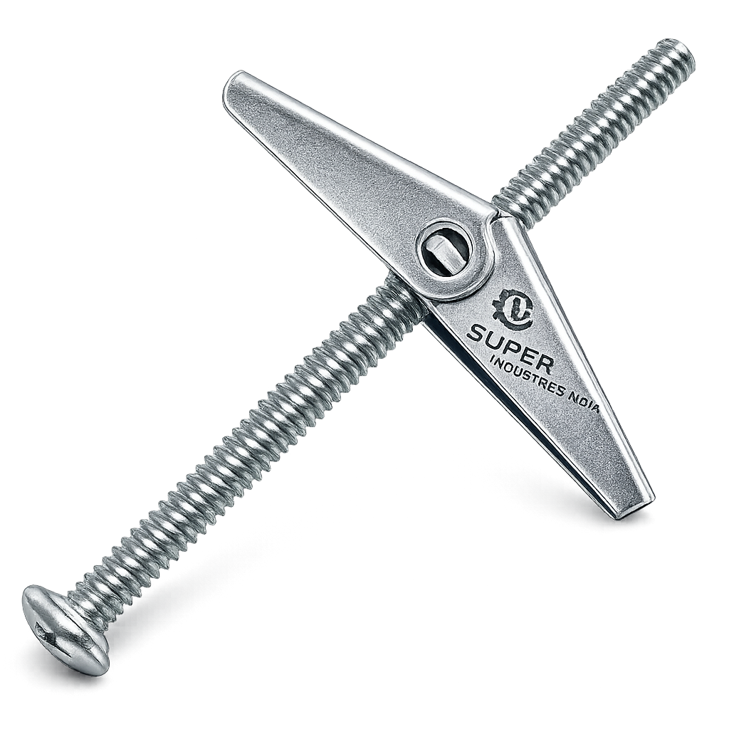
Mechanical fastening systems designed for hollow substrates, utilizing a spring-loaded wing mechanism that expands behind the installation surface to provide load-bearing anchorage through backside engagement.
Core Components
1. Machine Screw (Bolt)
- Typically metric (M4–M12) or imperial sizes
- Provides tensile and shear load capacity
2. Toggle Wings
- Two hinged metal arms
- Expand after passing through substrate
3. Spring Mechanism
- Maintains wing alignment during insertion
- Ensures automatic deployment inside cavity
4. Bearing Surface
- Contact area behind substrate
- Responsible for load distribution
Insertion & Activation Mechanics
Step 1: Folded Insertion
- Wings collapse along the bolt axis
- Assembly passes through drilled hole
Step 2: Cavity Entry
- Once inside hollow space, spring activates
Step 3: Wing Expansion
- Wings open perpendicular to bolt
Step 4: Tightening
- Bolt is pulled back
- Wings engage rear surface of wall
Open-Wing vs Folded State
| State | Description | Engineering Relevance |
|---|---|---|
| Folded | During insertion | Enables passage through hole |
| Open | After cavity entry | Provides load-bearing surface |
3. Engineering & Load Distribution Principle
Fundamental Load Transfer Mechanism
Toggle bolts operate on a reverse bearing principle:
- Load is transferred from bolt → wings → backside of substrate
- Unlike expansion anchors, force is not radial but planar
Tensile Load Resistance (Pull-Out)
Pull-out resistance is governed by:
- Wing bearing area
- Substrate strength
- Distance from hole edge
Mechanism:
- Applied tensile force pulls bolt outward
- Wings resist movement by pressing against inner wall surface
- Load spreads over a larger contact area, reducing failure risk
Shear Load Handling
Shear forces act:
- Parallel to wall surface
Resistance depends on:
- Bolt diameter
- Material strength
- Tightening condition
Failure risk increases when:
- Load is eccentric
- Wall thickness is insufficient
Bearing Area Expansion
Key advantage:
- Toggle wings create a distributed bearing footprint
This reduces:
- Local stress concentration
- Risk of gypsum fracture
Toggle Span vs Load Capacity
There is a direct relationship:
- Larger wing span → higher load distribution → improved capacity
However:
- Limited by cavity size
- Installation constraints
Failure Modes
1. Wall Crushing
- Occurs in weak drywall
- Due to excessive bearing stress
2. Bolt Shear Failure
- Occurs under high lateral loads
- Depends on material grade
3. Wing Deformation
- Result of overloading
- Leads to reduced anchoring capacity
Comparison with Point Load Anchors
| Parameter | Toggle Bolts | Expansion Anchors |
|---|---|---|
| Load Distribution | Wide area | Localized |
| Suitable Substrate | Hollow | Solid |
| Pull-Out Resistance | High (in hollow walls) | Low (in hollow walls) |
Effect of Cavity Depth
Cavity depth influences:
- Wing opening efficiency
- Load distribution angle
If cavity is too shallow:
- Wings may not fully deploy
- Load capacity reduces significantly
Super Industries
Global Manufacturer of Heavy & Custom Engineered Fasteners & Flanges
4. Load & Strength Engineering
Safe Working Load (SWL)
Defined as:
Maximum load that can be safely applied under service conditions.
SWL is derived from:
- Ultimate load capacity
- Divided by safety factor
Ultimate Load Capacity
Determined through:
- Laboratory pull-out testing
- Material strength evaluation
- Substrate interaction
Safety Factor Application
Typical safety factors:
- 3:1 for static loads
- 4–5:1 for dynamic or critical installations
Static vs Dynamic Loads
| Load Type | Characteristics | Design Consideration |
|---|---|---|
| Static | Constant load | Lower safety factor |
| Dynamic | Variable / vibrating | Higher safety factor |
Ceiling vs Wall Installations
Ceiling installations:
- Primarily tensile loading
- Higher risk → stricter safety factors
Wall installations:
- Combination of shear and tensile forces
Edge Distance Considerations
Minimum edge distance required to:
- Prevent cracking
- Ensure load distribution
Typical rule:
- ≥ 2× hole diameter
Spacing Requirements
- Prevent overlapping stress zones
- Maintain substrate integrity
Load Reduction Factors
Based on Drywall Thickness
| Thickness | Reduction Factor |
|---|---|
| 9 mm | 0.6 |
| 12 mm | 0.8 |
| 15 mm | 1.0 |
Environmental Influence
Moisture
- Weakens gypsum
- Reduces load capacity
Aging
- Material fatigue over time
- Reduction in anchoring performance
Dimensional & Design Logic
Standard Size Range
| Metric Size | Imperial Equivalent |
|---|---|
| M4 | #8 |
| M5 | #10 |
| M6 | 1/4″ |
| M8 | 5/16″ |
| M10 | 3/8″ |
| M12 | 1/2″ |
Critical Design Parameters
1. Hole Diameter
- Must accommodate folded wings
- Typically larger than bolt diameter
2. Toggle Wing Span
- Determines bearing area
- Must fit within cavity
3. Grip Range
- Thickness of material being fastened
4. Thread Length
- Must allow full engagement after installation
Sizing vs Wall Thickness
Incorrect sizing leads to:
- Incomplete wing deployment
- Reduced load capacity
Clearance vs Interference Fit
- Clearance required for insertion
- Excess clearance reduces stability
Installation Tolerances
- Hole diameter tolerance: ±0.5 mm
- Alignment critical for load distribution
5. Applicable Standards (ASTM / DIN / ISO / IFI)
Standards Framework for Toggle Bolts
While Toggle Bolts are application-specific fastening systems, their individual components and performance characteristics are governed by internationally recognized standards. These standards ensure:
- Mechanical reliability
- Dimensional consistency
- Thread compatibility
- Corrosion performance
- Inspection traceability
Relevant ASTM Standards
ASTM A307 – Carbon Steel Bolts
Applies to:
- Low and medium carbon steel bolts used in general applications
- Machine screws used in toggle bolt assemblies
Engineering Relevance:
- Defines minimum tensile strength (~414 MPa)
- Ensures predictable behavior under tensile loading
- Suitable for non-critical structural applications
ASTM A193 – Alloy Steel & Stainless Steel Bolting
Applicable where:
- Higher strength or elevated temperature performance is required
- Toggle bolts are used in industrial or engineered environments
Engineering Relevance:
- Covers high-strength bolting materials
- Ensures performance under stress and temperature variation
- Used for engineered-grade toggle assemblies
DIN Standards (German Fastening Standards)
DIN standards govern:
- Bolt geometry
- Thread profiles
- Dimensional tolerances
Relevant DIN references include:
- DIN 933 / DIN 931 – Hex bolts (geometry reference)
- DIN 975 / DIN 976 – Threading standards
Engineering Relevance:
- Ensures interchangeability across international systems
- Maintains dimensional accuracy for assembly
ISO Standards
ISO 898-1 – Mechanical Properties of Fasteners
Defines:
- Yield strength
- Tensile strength
- Mechanical classification
ISO 965 – Thread Tolerances
Controls:
- Thread fit (6g, 6H classes)
- Assembly compatibility
IFI (Industrial Fastener Institute) Standards
IFI provides:
- Dimensional guidance for non-standard fasteners
- Performance recommendations
- Load testing methodologies
Standards Mapping to Engineering Requirements
| Engineering Requirement | Applicable Standard |
|---|---|
| Tensile strength | ASTM A307 / ASTM A193 / ISO 898 |
| Thread compatibility | ISO 965 |
| Dimensional accuracy | DIN / IFI |
| Performance testing | IFI / ASTM |
| Corrosion resistance | ASTM B117 (salt spray) |
Standards vs Application Environment
| Environment | Recommended Standard Alignment |
|---|---|
| Indoor drywall | ASTM A307 + Zinc plating |
| Industrial interiors | ISO 898 + controlled coatings |
| Outdoor exposure | ASTM A193 / SS grades |
| Marine / humid | SS316 + passivation |
Material & Grade Options
Material Selection Philosophy
Material selection for Toggle Bolts is governed by:
- Load requirements
- Environmental exposure
- Corrosion resistance
- Lifecycle expectations
1. Carbon Steel
Low Carbon Steel (Zinc Plated)
- Most commonly used material
- Economical and widely available
Characteristics:
- Moderate tensile strength
- Requires coating for corrosion protection
- Suitable for indoor use
2. Stainless Steel
SS 304 (A2 Grade)
- Austenitic stainless steel
- General corrosion resistance
Applications:
- Humid interiors
- Commercial buildings
SS 316 (A4 Grade)
- Enhanced corrosion resistance due to molybdenum content
Applications:
- Coastal environments
- Chemical exposure zones
- Marine installations
3. Alloy Steel (Engineered Applications)
Used where:
- Higher strength is required
- Load conditions exceed standard carbon steel limits
Characteristics:
- Higher tensile and yield strength
- May require heat treatment
- Requires protective coating
Material Selection Considerations
| Parameter | Carbon Steel | SS304 | SS316 | Alloy Steel |
|---|---|---|---|---|
| Strength | Moderate | Moderate | Moderate | High |
| Corrosion Resistance | Low (coated) | Good | Excellent | Low (coated) |
| Cost | Low | Medium | High | Medium–High |
| Application | Indoor | Humid indoor | Marine | High load |
Mandatory Material Comparison Table
| Grade | Yield Strength (MPa) | Tensile Strength (MPa) | Corrosion Resistance | Load Capacity Suitability | Typical Applications |
|---|---|---|---|---|---|
| Low Carbon Steel | ~250 | ~400–450 | Low (requires coating) | Standard duty | Drywall, interiors |
| SS 304 | ~215 | ~500–700 | Good | Medium duty | Commercial interiors |
| SS 316 | ~205 | ~500–700 | Excellent | Medium duty | Marine, coastal |
| Alloy Steel | 600+ | 800+ | Low (coated) | High duty | Industrial systems |
6. Heat Treatment Information
Purpose of Heat Treatment
Heat treatment is applied to:
- Improve mechanical strength
- Enhance thread durability
- Reduce internal stresses
Processes Applied
1. Case Hardening (Selective)
- Applied to threaded portions
- Improves surface hardness
Benefit:
- Increased wear resistance
- Reduced thread deformation during tightening
2. Through Hardening (Alloy Steel)
- Uniform hardness across bolt
Benefit:
- Improved tensile strength
- Better shear resistance
3. Stress Relieving
- Applied after cold forming
Purpose:
- Remove residual stresses
- Improve dimensional stability
Hardness Ranges
| Material | Hardness (HRC) |
|---|---|
| Carbon Steel | 20–30 |
| Alloy Steel | 30–45 |
| Stainless Steel | 15–25 |
Effect on Performance
| Property | Effect of Heat Treatment |
|---|---|
| Tensile Strength | Increased |
| Fatigue Resistance | Improved |
| Thread Life | Extended |
| Brittleness | Must be controlled |
Manufacturing Process
Controlled Manufacturing Workflow
1. Raw Material Inspection
- Chemical composition verification
- Mechanical property validation
2. Wire Drawing
- Reduces diameter to required size
- Improves grain alignment
3. Cold Forming / Heading
- Bolt head formation
- High dimensional accuracy
4. Thread Rolling
- Threads formed (not cut)
- Improves strength through grain flow continuity
5. Wing Stamping & Forming
- Precision stamping of toggle wings
- Controlled geometry for consistent deployment
6. Spring Assembly
- Spring inserted between wings
- Ensures controlled opening force
7. Assembly Integration
- Bolt + wing + spring assembled
- Functional movement checked
8. Surface Coating
- Zinc plating / galvanizing / passivation
- Corrosion protection applied
9. Final Inspection
- Dimensional checks
- Functional deployment testing
10. Packaging & Traceability
- Batch identification
- Lot traceability for project compliance
Surface Finish Options
1. Zinc Plating (Electroplated)
- Clear (blue/white)
- Yellow passivation
Characteristics:
- Basic corrosion resistance
- Suitable for indoor use
2. Hot-Dip Galvanizing
- Thick zinc coating
Advantages:
- Improved corrosion protection
- Suitable for outdoor applications
Limitations:
- Thread fit must be controlled
3. Mechanical Galvanizing
- Uniform coating without hydrogen embrittlement
4. PTFE Coating
- Reduces friction
- Improves installation
5. Stainless Steel Passivation
- Removes free iron
- Enhances corrosion resistance
Corrosion Performance Overview
| Finish | Corrosion Resistance | Application |
|---|---|---|
| Zinc Plated | Moderate | Indoor |
| HDG | High | Outdoor |
| Mechanical Galvanized | High | Structural |
| PTFE | Moderate + friction control | Specialized |
| SS Passivated | Very High | Marine |
Engineering Consideration: Coating vs Thread Fit
Coatings influence:
- Thread tolerance
- Assembly torque
- Installation performance
Proper allowance must be made for:
- Coating thickness
- Thread class (e.g., 6g/6H)
A. Technical Dimension Tables for Toggle Bolts
The dimensional configuration of Toggle Bolts governs installation feasibility, load distribution, and anchoring performance. The following table provides typical engineering reference values used in EPC evaluation and design coordination.
Note: Values are indicative and must be verified against project-specific testing and substrate conditions.
Standard Dimension Table
| Bolt Size | Hole Diameter (mm) | Toggle Wing Span (mm) | Grip Range (mm) | Bolt Length (mm) | Recommended Load (kg) |
|---|---|---|---|---|---|
| M4 | 10–12 | 25–30 | 3–12 | 50–75 | 10–15 |
| M5 | 12–14 | 30–35 | 5–15 | 60–90 | 15–25 |
| M6 | 14–16 | 35–45 | 6–20 | 70–100 | 25–40 |
| M8 | 18–20 | 50–60 | 8–25 | 80–120 | 40–70 |
| M10 | 20–24 | 60–75 | 10–30 | 100–150 | 70–120 |
| M12 | 24–28 | 75–90 | 12–35 | 120–180 | 120–180 |
Engineering Observations
- Hole diameter must accommodate folded wings, not just bolt diameter
- Wing span directly influences bearing area and pull-out resistance
- Grip range must match substrate + fixture thickness
- Oversized holes reduce load capacity due to reduced bearing stability
B. Load Capacity Table (Drywall-Based Reference)
Load capacity varies significantly based on drywall thickness and material condition. The following table incorporates typical safety factors (≥3).
Load Capacity vs Substrate Thickness
| Bolt Size | 9 mm Drywall (kg) | 12 mm Drywall (kg) | 15 mm Drywall (kg) |
|---|---|---|---|
| M4 | 6–10 | 10–12 | 12–15 |
| M5 | 10–15 | 15–20 | 20–25 |
| M6 | 15–25 | 25–35 | 35–40 |
| M8 | 25–40 | 40–60 | 60–70 |
| M10 | 40–70 | 70–100 | 100–120 |
| M12 | 70–120 | 120–160 | 150–180 |
Engineering Considerations
- Values represent Safe Working Load (SWL)
- Ultimate load capacity is typically 3–5× higher
- Ceiling installations should use higher safety factors (≥4)
- Moisture exposure reduces capacity by 15–30%
C. Torque Guidelines (Critical for Installation Integrity)
Proper torque application is essential to:
- Ensure wing seating behind substrate
- Avoid drywall crushing
- Prevent thread stripping
Recommended Torque Values
| Bolt Size | Recommended Torque (Nm) | Remarks |
|---|---|---|
| M4 | 1.5 – 2.5 | Light fixtures |
| M5 | 2.5 – 4 | Medium loads |
| M6 | 4 – 6 | Standard installations |
| M8 | 8 – 12 | Heavy-duty applications |
| M10 | 12 – 18 | Structural attachments |
| M12 | 18 – 25 | High load conditions |
Torque Engineering Notes
- Over-tightening leads to:
- Drywall crushing
- Loss of load distribution
- Reduced anchor capacity
- Under-tightening results in:
- Improper wing seating
- Reduced pull-out resistance
D. Load Calculation Guide (Engineering Basis)
1. Tensile Load Calculation
Where:
- (F_t) = Allowable tensile load
- (A_b) = Effective bearing area (mm²)
- (\sigma_y) = Yield strength of material (MPa)
- (SF) = Safety factor
2. Shear Load Estimation
Where:
- (F_s) = Allowable shear load
- (A_s) = Bolt cross-sectional area
3. Safety Factor Application
Typical values:
| Condition | Safety Factor |
|---|---|
| Static load | 3 |
| Dynamic load | 4–5 |
| Ceiling installation | ≥4 |
4. Sample Engineering Calculation
Given:
- Bolt size: M8
- Yield strength: 400 MPa
- Effective bearing area: 300 mm²
- Safety factor: 4
Step 1: Tensile Load
[
![\[F_ t = \frac{300 \times 400}{4} = 30{,}000 \, \text{N} = 30 \, \text{kN}\]](https://superindustriesindia.in/wp-content/ql-cache/quicklatex.com-ea8c95d848334a36f69211f4d2587018_l3.png "Rendered by QuickLaTeX.com")
Step 2: Apply Drywall Reduction Factor (0.8)
![\[\text{Adjusted Load} = 30 \times 0.8 = 24 \, \text{kN}\]](https://superindustriesindia.in/wp-content/ql-cache/quicklatex.com-0a1fdec794090dfcbf8979a591afd980_l3.png "Rendered by QuickLaTeX.com")
Step 3: Convert to Practical Load
- Considering installation conditions and uncertainties:
→ Final recommended SWL ≈ 4–6 kN
Engineering Interpretation
- Theoretical load must always be reduced based on:
- Substrate strength
- Installation quality
- Environmental factors
E. Mechanical Property Table
Typical Mechanical Properties
| Material | Yield Strength (MPa) | Tensile Strength (MPa) | Hardness (HRC) |
|---|---|---|---|
| Carbon Steel | 240–260 | 400–450 | 20–30 |
| SS304 | ~215 | 500–700 | 15–25 |
| SS316 | ~205 | 500–700 | 15–25 |
| Alloy Steel | 600+ | 800+ | 30–45 |
Engineering Notes
- Higher tensile strength improves:
- Shear resistance
- Load capacity
- Hardness must be controlled to:
- Avoid brittleness
- Maintain ductility
F. Corrosion Resistance Table
Environment-Based Selection Guide
| Surface Finish / Material | Indoor | Outdoor | Humid | Marine |
|---|---|---|---|---|
| Zinc Plated | Suitable | Limited | Moderate | Not recommended |
| Hot-Dip Galvanized | Suitable | Suitable | Good | Limited |
| SS304 | Suitable | Suitable | Good | Moderate |
| SS316 | Suitable | Suitable | Excellent | Recommended |
Engineering Observations
- Corrosion directly impacts:
- Thread integrity
- Load capacity over time
- Stainless steel preferred for:
- Long lifecycle
- High humidity environments
7. Inspection & Quality Control Methods
1. Dimensional Inspection
- Verification of:
- Bolt diameter
- Length
- Wing span
- Hole compatibility
Tools Used:
- Vernier calipers
- Micrometers
2. Thread Gauge Testing
- GO / NO-GO gauges
- Ensures compliance with ISO thread standards
3. Load Testing (Pull-Out Test)
- Conducted on representative substrates
- Determines:
- Ultimate load
- Failure mode
4. Coating Thickness Testing
- Magnetic thickness gauge
- Ensures corrosion protection compliance
5. Salt Spray Testing (ASTM B117)
- Simulates corrosive environments
- Measures coating durability
6. Hardness Testing
- Rockwell hardness test
- Confirms heat treatment effectiveness
7. Functional Deployment Testing
- Verifies:
- Wing opening performance
- Spring reliability
8. Third-Party Inspection (TPI)
Commonly required for EPC projects:
- Independent inspection agencies
- Witness testing and documentation
9. Certification
EN 10204 3.1
- Manufacturer test certificate
EN 10204 3.2
- Third-party verified certificate
Inspection Summary Table
| Inspection Type | Purpose |
|---|---|
| Dimensional | Fit and compatibility |
| Mechanical | Strength verification |
| Coating | Corrosion protection |
| Functional | Deployment reliability |
| Third-party | Project compliance |
Engineering Compliance Outcome
A properly inspected toggle bolt system ensures:
- Predictable load performance
- Installation reliability
- Long-term structural integrity
8. Industries Served
The application of Toggle Bolts extends across multiple engineering domains where hollow or low-density substrates are present. Their selection is based on load conditions, accessibility constraints, and installation environments.
1. Commercial Construction
Applications:
- Partition wall installations
- Interior fixture mounting
- Suspended ceilings
Engineering Considerations:
- Drywall thickness variability
- High installation volume
- Load uniformity across multiple anchor points
2. Infrastructure Projects
Applications:
- Utility installations in transit systems
- Public facility interiors
- Panel-based wall systems
Engineering Considerations:
- Compliance with project specifications
- Long-term durability requirements
- Inspection and maintenance access
3. HVAC Installations
Applications:
- Air duct suspension
- Diffuser mounting
- Light mechanical support
Engineering Considerations:
- Dynamic loads (vibration)
- Ceiling-based installations
- Load redistribution requirements
4. Electrical Systems
Applications:
- Cable tray support
- Junction box mounting
- Lighting fixture installation
Engineering Considerations:
- Combined tensile and shear loads
- Accessibility constraints inside cavities
- Fire safety compliance
5. Plumbing Systems
Applications:
- Pipe supports in hollow partitions
- Lightweight piping systems
Engineering Considerations:
- Moisture exposure
- Corrosion resistance
- Load variability due to fluid movement
6. Modular & Prefabricated Construction
Applications:
- Panelized structures
- Pre-engineered wall systems
- Relocatable infrastructure
Engineering Considerations:
- Repeatability of installation
- Standardized dimensions
- Reduced on-site variability
7. Interior & Architectural Systems
Applications:
- False ceiling grids
- Decorative panel mounting
- Lightweight structural attachments
Engineering Considerations:
- Aesthetic constraints
- Limited substrate strength
- Precision installation
Export Capability & Global Supply
Global Supply Framework
Super Industries operates as a manufacturer and exporter of Toggle Bolts aligned with international project requirements and procurement practices.
Regions Served
- United States
- European Union
- Middle East (GCC countries)
- Southeast Asia
- Africa (project-based supply)
Export-Oriented Manufacturing Approach
1. Batch Traceability
- Heat number tracking
- Lot-wise identification
- Inspection record linkage
2. Documentation Support
Provided with each shipment:
- Material Test Certificates (EN 10204 3.1 / 3.2)
- Dimensional inspection reports
- Coating test reports
- Compliance declarations
3. Packaging Standards
- Export-grade packaging
- Moisture-resistant wrapping
- Palletized shipment units
- Marked cartons with traceability codes
4. Bulk Supply Capability
- High-volume production for EPC projects
- Consistent batch quality
- Controlled lead times
5. Logistics Coordination
- Containerized shipments (FCL/LCL)
- Port-to-port delivery
- Coordination with freight forwarders
Engineering-Oriented Export Considerations
- Compliance with destination country standards
- Coating selection based on climate
- Packaging based on transit duration
- Documentation aligned with inspection agencies
Procurement & Installation Engineering View
1. Drilling Requirements
Proper hole preparation is critical:
- Hole diameter must match toggle specification
- Clean drilling without edge damage
- Avoid oversizing beyond tolerance
2. Hole Size Accuracy
| Parameter | Requirement |
|---|---|
| Diameter tolerance | ±0.5 mm |
| Alignment | Perpendicular to surface |
| Edge integrity | No cracking or chipping |
3. Wing Deployment Mechanism
Installation sequence:
- Wings folded along bolt axis
- Inserted through drilled hole
- Enter cavity and expand automatically
- Bolt pulled back to seat wings
- Tightening performed
4. Tightening Control
- Apply controlled torque (refer Part 3)
- Avoid excessive compression of drywall
- Ensure full seating of wings
5. Load Testing After Installation
Recommended for critical applications:
- Sample pull-out testing
- Verification of anchor performance
- Documentation for inspection
9.Installation Errors to Avoid
1. Oversized Hole
- Leads to reduced bearing capacity
- Causes instability
2. Incomplete Wing Deployment
- Occurs in shallow cavities
- Results in reduced load capacity
3. Over-Tightening
- Causes drywall crushing
- Reduces load distribution effectiveness
4. Misalignment
- Induces eccentric loading
- Increases failure risk
5. Incorrect Grip Length Selection
- Prevents proper engagement
- Reduces anchoring reliability
Reusability Considerations
- Toggle bolts are generally non-reusable
- Once installed and removed:
- Wings detach inside cavity
- Replacement required
10.Inspection Checklist (Field Use)
Pre-Installation
- Verify substrate thickness
- Confirm hole diameter
- Check bolt size and length
During Installation
- Ensure proper wing deployment
- Maintain alignment
- Apply correct torque
Post-Installation
- Check fixture stability
- Conduct load verification (if required)
- Record installation data (for EPC projects)
11.Custom Engineering Capabilities
Super Industries supports project-specific requirements for Toggle Bolts through controlled manufacturing and engineering adaptation.
1. Extended Bolt Lengths
- For thicker assemblies
- Multi-layer installations
2. Special Coatings
- PTFE coatings for reduced friction
- Enhanced galvanization thickness
- Custom corrosion protection systems
3. Custom Thread Sizes
- Metric and imperial variants
- Project-specific tolerances
4. Heavy-Duty Toggle Designs
- Increased wing span
- Reinforced components
- Higher load capacity configurations
5. Project-Specific Packaging & Marking
- Barcode labeling
- Batch traceability marking
- Custom carton identification
Engineering Summary & Technical Conclusion
Functional Role
Toggle Bolts provide a reliable fastening solution for:
- Hollow substrates
- Low-density materials
- Non-load-bearing structural applications
Engineering Advantages
- Backside load distribution
- Reduced surface stress
- Adaptability to varying wall thickness
Critical Design Dependencies
Performance depends on:
- Proper sizing
- Correct installation
- Substrate condition
- Environmental exposure
Limitations
- Not suitable for heavy structural loads
- Performance dependent on drywall integrity
- Limited reusability
EPC Evaluation Perspective
From an engineering and procurement standpoint, a compliant toggle bolt system must demonstrate:
- Verified load performance
- Material traceability
- Standard compliance
- Installation reliability
- Inspection readiness
Final Engineering Statement
A correctly specified and installed Toggle Bolts system ensures:
- Controlled load transfer in hollow substrates
- Predictable performance under service conditions
- Compatibility with global EPC project requirements