
WEDGE ANCHOR BOLTS
Super Industries
“Global Manufacturer of Heavy & Custom Engineered Fasteners for Oil & Gas, Power & EPC Contractors.”
1. Industry Context & System Relevance
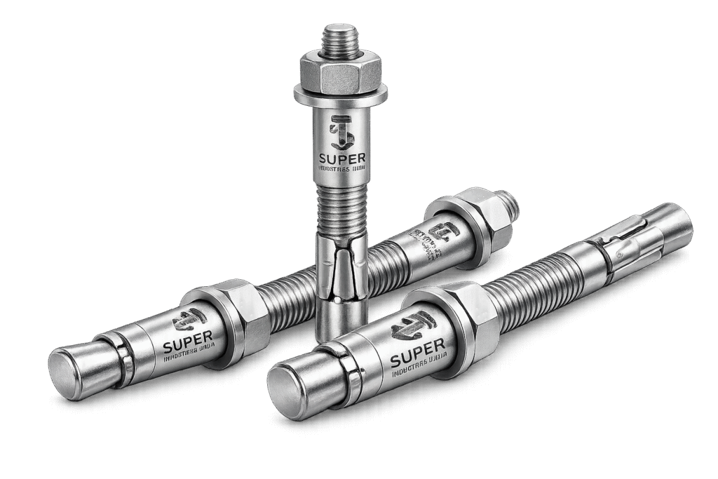
Role of Wedge Anchor Bolts in Structural Anchoring Systems
Wedge Anchor Bolts are post-installed mechanical anchoring systems used to transfer structural and non-structural loads from fixtures into hardened concrete. Their function is critical in applications where cast-in anchoring is not feasible and load-bearing connections must be established after concrete curing.
They operate within the broader category of mechanical expansion anchors, providing immediate load-carrying capability upon installation.
Application Domains
1. Reinforced Concrete Structures
Used for anchoring structural steel elements such as beams, brackets, and supports into reinforced concrete members. Load transfer occurs through friction and localized bearing within the concrete matrix.
2. Industrial Equipment Anchoring
Applicable for fixing rotating and static machinery where vibration, dynamic loads, and alignment precision are involved.
3. Steel Column Base Plates
Provide post-installed anchorage where base plate alignment or late-stage modifications are required in EPC projects.
4. Heavy Machinery Foundations
Used in turbine bases, compressors, pumps, and fabrication equipment installations where anchor reliability under cyclic loads is required.
5. Oil & Gas Infrastructure
Deployed in pipe supports, skids, process modules, and structural frames in both upstream and downstream facilities.
6. Power Plants
Used in anchoring equipment such as boilers, transformers, cable trays, and auxiliary structural supports.
7. Metro & Rail Projects
Applied in track-side equipment, station infrastructure, cable management systems, and signaling installations.
8. Bridges & Infrastructure
Utilized for retrofitting, railing installations, lighting systems, and maintenance access structures.
Why Mechanical Expansion Anchors Are Used
Mechanical expansion anchors such as Wedge Anchor Bolts are selected when:
- Immediate load application is required (no curing time)
- Installation must be verifiable via torque control
- Predictable performance is needed in standardized conditions
- On-site flexibility is required for alignment adjustments
- Environmental conditions do not favor chemical anchoring
Comparison with Other Anchoring Systems
| Parameter | Wedge Anchor Bolts | Cast-In Anchors | Chemical Anchors |
|---|---|---|---|
| Installation Stage | Post-installed | Pre-installed | Post-installed |
| Load Readiness | Immediate | Immediate | Delayed (curing required) |
| Installation Control | Torque-based | Placement-based | Injection-based |
| Suitability for Retrofits | Yes | No | Yes |
| Performance in Cracked Concrete | Limited (unless certified) | High | High (depending on resin) |
| Sensitivity to Installation Quality | Moderate | Low | High |
Suitability: Cracked vs Non-Cracked Concrete
Wedge Anchor Bolts are primarily used in:
- Non-cracked concrete where stress conditions remain below cracking thresholds
- Limited use in cracked concrete when:
- Approved under ETAG/EAD
- Tested for seismic and dynamic conditions
In cracked concrete, anchor performance depends on:
- Expansion reliability under cyclic crack movement
- Load redistribution within fractured concrete zones
2. Technical Definition
Engineering Definition
Wedge Anchor Bolts are:
Torque-controlled, post-installed mechanical expansion anchors designed to transfer tensile and shear loads into concrete through radial expansion forces generated by a wedge mechanism.
Core Characteristics
- Mechanical expansion-based anchoring
- Torque-induced activation
- Friction + mechanical interlock load transfer
- Suitable for static and moderate dynamic loading
Component Description
1. Threaded Stud
- Main load-carrying element
- Transfers tensile and shear forces
- Manufactured with rolled threads for strength consistency
2. Expansion Clip (Wedge Mechanism)
- Located at embedded end
- Expands radially under torque
- Generates frictional resistance against drilled hole walls
3. Nut and Washer
- Facilitate torque application
- Distribute clamping force across fixture surface
Working Mechanism
Step-by-Step Mechanical Behavior
- Anchor inserted into drilled hole
- Nut tightened using calibrated torque
- Threaded stud is pulled upward relative to expansion clip
- Expansion clip wedges outward
- Radial pressure develops against concrete surface
- Friction and bearing resistance resist applied loads
3. Engineering & Load Transfer Principle
Expansion Mechanics
The performance of Wedge Anchor Bolts is governed by:
- Controlled radial expansion
- Contact pressure between clip and concrete
- Frictional resistance along embedment depth
The anchor transforms torque input → axial force → radial expansion → frictional resistance
Load Transfer Mechanisms
1. Tension Load (Pull-Out Resistance)
Resisted through:
- Friction between expanded clip and concrete
- Mechanical interlock (limited)
- Concrete cone resistance at higher loads
2. Shear Load
Transferred via:
- Bearing of stud against concrete wall
- Shear strength of steel
- Friction at fixture interface
3. Combined Loading
In real conditions, anchors experience:
- Simultaneous tension + shear
- Interaction governed by design codes (EN 1992-4)
Concrete Cone Failure Theory
Under tensile loading:
- A conical failure surface develops from anchor embedment depth
- Failure occurs when tensile stress exceeds concrete tensile strength
Cone angle ≈ 35°–45° depending on concrete properties
Failure Mode Hierarchy
- Steel failure (ductile)
- Concrete cone failure
- Pull-out failure
- Splitting failure
Design aims to ensure:
Controlled, predictable failure — preferably steel governed
Edge Distance Influence
Reduced edge distance leads to:
- Reduced concrete confinement
- Increased risk of splitting
- Lower load capacity
Spacing Effect
Closely spaced anchors:
- Cause overlapping stress cones
- Reduce effective load capacity per anchor
- Require reduction factors
4. Load & Performance Engineering
Tension Load Capacity
Depends on:
- Embedment depth
- Concrete strength
- Anchor diameter
- Expansion efficiency
Shear Load Capacity
Depends on:
- Steel shear strength
- Edge distance
- Fixture stiffness
Combined Loading Interaction
Governed by interaction equation:
[
\left( \frac{N}{N_{allow}} \right)^a + \left( \frac{V}{V_{allow}} \right)^b \leq 1
]
Where:
- N = Applied tensile load
- V = Applied shear load
Static vs Dynamic Loads
Static Loads
- Constant magnitude
- Predictable stress distribution
Dynamic Loads
- Vibration
- Impact loads
- Require fatigue consideration
Seismic Considerations
For seismic zones:
- Anchors must resist cyclic loading
- Performance depends on:
- Crack tolerance
- Energy dissipation
- Qualification per EAD/ETAG
Fatigue Resistance
Critical for:
- Rotating equipment
- Infrastructure subject to repeated loading
Fatigue life influenced by:
- Stress range
- Material properties
- Installation quality
Safety Factors
Typical approach:
- Global safety factor: 3 to 5
- Partial safety factors (Eurocode):
- Concrete: γc
- Steel: γs
Failure Modes (Detailed)
1. Pull-Out Failure
- Insufficient expansion or poor installation
2. Concrete Cone Failure
- Occurs under high tensile loads
3. Steel Rupture
- Occurs when steel capacity is exceeded
4. Splitting Failure
- Occurs due to insufficient edge distance or spacing
Dimensional & Design Logic
Key Parameters
1. Anchor Diameter
Defines:
- Load capacity
- Required hole size
- Torque value
2. Effective Embedment Depth (hef)
Critical parameter controlling:
- Pull-out resistance
- Cone failure capacity
3. Drill Hole Diameter
Must match:
- Manufacturer tolerance
- Expansion clip design
4. Edge Distance
Minimum required to prevent:
- Concrete splitting
- Reduced capacity
5. Anchor Spacing
Controls:
- Load interaction
- Group efficiency
6. Thread Length
Determines:
- Fixture thickness compatibility
- Engagement length for nut
7. Overall Length
= Embedment depth + fixture thickness + nut allowance
Tolerance Requirements
- Hole diameter tolerance: ±0.1–0.3 mm
- Anchor straightness
- Thread accuracy per ISO standards
Installation Depth Control
Critical for:
- Ensuring full expansion
- Achieving rated load capacity
Depth must be:
- Verified during installation
- Consistent across anchors
Hole Cleaning Importance
Improper cleaning leads to:
- Reduced friction
- Lower load capacity
- Increased risk of pull-out failure
Standard cleaning method:
- Blow (compressed air)
- Brush
- Blow again
4. Applicable Standards (ASTM / DIN / ISO / EN)
Standards Framework for Wedge Anchor Bolts
The design, manufacturing, and performance validation of Wedge Anchor Bolts are governed by a combination of material standards, anchoring design codes, and qualification guidelines. These standards ensure compatibility with structural design methodologies and EPC project specifications.
ASTM Standards
ASTM F1554 — Anchor Bolts (General Reference)
Although primarily intended for cast-in-place anchor bolts, ASTM F1554 provides baseline requirements for:
- Mechanical properties
- Yield strength classification (Grade 36, 55, 105)
- Material traceability
Used as a reference in procurement specifications where anchoring elements are evaluated for structural consistency.
ASTM A307 — Carbon Steel Bolts
Applicable for:
- Low to medium strength Wedge Anchor Bolts
- Non-critical anchoring applications
Characteristics:
- Tensile strength: ~414 MPa (min)
- Suitable for general construction anchoring
ASTM A193 Grade B7 — Alloy Steel (High Strength)
Used in:
- High-load applications
- Elevated temperature environments
Characteristics:
- Heat-treated alloy steel
- High tensile and yield strength
- Suitable for power, oil & gas installations
EN Standards (European Framework)
EN 1992-4 — Design of Fastenings for Use in Concrete
Primary design standard for post-installed anchors, including Wedge Anchor Bolts.
Defines:
- Design methodology for tension and shear loads
- Partial safety factors
- Failure modes:
- Concrete cone
- Steel failure
- Pull-out
- Splitting
Critical for:
- Structural engineers
- EPC design validation
- Consultant approvals
ETAG 001 / EAD (European Assessment Documents)
Provide:
- Qualification procedures for mechanical anchors
- Testing under:
- Cracked concrete
- Seismic loading (C1, C2 categories)
- Fatigue conditions
Used for:
- Product approval in EU markets
- Performance certification
ISO Standards
Applicable areas:
- Thread tolerances — ISO 965
- Mechanical testing — ISO 898-1
- Corrosion testing — ISO 9227 (salt spray)
Ensure:
- Interchangeability
- Global compliance
- Dimensional consistency
Standards Mapping to Engineering Requirements
| Requirement | Applicable Standard |
|---|---|
| Structural design | EN 1992-4 |
| Material strength | ASTM A307 / A193 / ISO 898 |
| Thread geometry | ISO 965 |
| Corrosion testing | ISO 9227 |
| Anchor qualification | ETAG 001 / EAD |
5. Material & Grade Options
Material Selection Philosophy
Material selection for Wedge Anchor Bolts is governed by:
- Required load capacity
- Environmental exposure
- Temperature conditions
- Corrosion risk
- Design life expectations
Carbon Steel Options
ASTM A307
- Low carbon steel
- Suitable for light to moderate structural loads
- Used in general construction anchoring
ASTM A36
- Structural-grade steel
- Moderate strength
- Used where weldability and structural compatibility are required
ASTM A193 Grade B7
- Alloy steel (Cr-Mo)
- Heat-treated (quenched & tempered)
- High strength, suitable for demanding environments
Stainless Steel Options
SS304 (A2-70 Equivalent)
- Austenitic stainless steel
- Moderate corrosion resistance
- Suitable for indoor and mildly corrosive environments
SS316 (A4-70 Equivalent)
- Enhanced corrosion resistance due to molybdenum content
- Suitable for:
- Marine environments
- Chemical exposure
- High humidity zones
High-Performance Materials
Duplex Stainless Steel (If Specified)
- Higher strength than austenitic grades
- Improved resistance to:
- Stress corrosion cracking
- Chloride environments
Used in:
- Offshore platforms
- Aggressive industrial environments
Material Comparison Table (Mandatory)
| Grade | Yield Strength (MPa) | Tensile Strength (MPa) | Corrosion Resistance | Temperature Range | Application |
|---|---|---|---|---|---|
| ASTM A307 | ~250 | ~414 | Low | -20°C to 200°C | General construction |
| ASTM A36 | ~250 | ~400–550 | Low | -20°C to 250°C | Structural anchoring |
| ASTM A193 B7 | ~720 | ~860–1000 | Moderate | -50°C to 450°C | High-load, oil & gas |
| SS304 | ~210 | ~520–750 | Moderate | -200°C to 400°C | Indoor / humid |
| SS316 | ~205 | ~515–750 | High | -200°C to 450°C | Marine / chemical |
| Duplex SS | ~450 | ~620–880 | Very High | -50°C to 300°C | Offshore / aggressive |
Material Behavior Considerations
Yield Strength
Controls:
- Elastic deformation limit
- Structural reliability under sustained load
Tensile Strength
Defines:
- Maximum load before rupture
- Governs steel failure mode
Corrosion Resistance
Critical for:
- Service life
- Maintenance requirements
- Structural safety in aggressive environments
Temperature Limits
Material performance varies under:
- Elevated temperatures (creep risk)
- Low temperatures (brittleness risk)
6. Heat Treatment Information
Purpose of Heat Treatment
Heat treatment is applied to Wedge Anchor Bolts (particularly alloy steel grades) to achieve:
- Required mechanical strength
- Controlled hardness
- Improved fatigue resistance
Quenching & Tempering
Quenching
- Rapid cooling from austenitizing temperature
- Produces hard martensitic structure
Tempering
- Reheating to controlled temperature
- Reduces brittleness
- Improves ductility and toughness
Stress Relieving
Applied to:
- Reduce residual stresses from forming and machining
- Improve dimensional stability
Hardness Control
Measured using:
- Rockwell (HRC)
- Brinell (HB)
Controlled hardness ensures:
- Resistance to deformation
- Avoidance of brittle fracture
Microstructure Influence
Heat treatment affects:
- Grain size
- Phase distribution (martensite, bainite, ferrite)
These directly influence:
- Strength
- Fatigue performance
- Crack propagation resistance
Brittleness vs Ductility Balance
Critical for anchoring systems:
- Excessive hardness → brittle failure risk
- Excessive ductility → deformation and loss of preload
Design objective:
Achieve controlled ductile behavior before failure
Manufacturing Process
Process Flow for Wedge Anchor Bolts
1. Raw Material Inspection
Verification of:
- Chemical composition
- Mechanical properties
- Mill test certificates
2. Cutting & Forming
- Bars cut to required length
- Headless studs formed
- Dimensional tolerances maintained
3. Thread Rolling
- Cold rolling process
- Improves:
- Surface finish
- Fatigue strength
- Thread accuracy
Threads comply with ISO metric standards.
4. Expansion Clip Manufacturing
- Precision stamping or forming
- Designed for controlled expansion characteristics
Critical parameters:
- Clip thickness
- Elastic recovery
- Expansion angle
5. Heat Treatment (If Applicable)
- Applied to alloy steel anchors (e.g., B7)
- Controlled furnace cycles
6. Surface Coating
Applied based on application:
- Zinc plating
- Hot-dip galvanizing
- PTFE coating
- Black oxide
7. Assembly
Components assembled:
- Stud + clip + washer + nut
Ensures:
- Proper clip positioning
- Functional expansion mechanism
8. Final Inspection
Verification of:
- Dimensions
- Thread quality
- Assembly integrity
9. Marking & Traceability
Includes:
- Heat number
- Grade identification
- Manufacturer identification (as specified)
Ensures:
- Full traceability for EPC documentation
7. Surface Finish Options
Surface Protection in Wedge Anchor Bolts
Surface finish directly influences:
- Corrosion resistance
- Service life
- Compatibility with environment
Available Finishes
1. Zinc Plated (Electroplated)
- Coating thickness: 5–25 microns
- Suitable for indoor applications
2. Hot-Dip Galvanized (HDG)
- Coating thickness: 50–85 microns
- Suitable for outdoor and industrial environments
3. Mechanical Galvanizing
- Uniform coating without hydrogen embrittlement risk
- Suitable for high-strength anchors
4. PTFE Coating
- Provides:
- Chemical resistance
- Low friction
- Used in aggressive environments
5. Black Oxide
- Minimal corrosion protection
- Used where coating thickness must be minimal
6. Passivation (Stainless Steel)
- Enhances corrosion resistance
- Removes free iron from surface
Corrosion Protection Performance
| Coating Type | Thickness | Corrosion Resistance | Typical Use |
|---|---|---|---|
| Zinc Plated | 5–25 µm | Low to Moderate | Indoor |
| HDG | 50–85 µm | High | Outdoor / industrial |
| Mechanical Galv. | 40–70 µm | Moderate to High | Structural |
| PTFE | Variable | Very High | Chemical exposure |
| Black Oxide | Minimal | Low | Controlled environments |
| SS Passivation | N/A | High | Marine / chemical |
Salt Spray Resistance (Indicative)
- Zinc plated: 72–120 hours
- HDG: 300–1000+ hours
- PTFE: Application dependent
A. Technical Dimension Tables
The dimensional configuration of Wedge Anchor Bolts governs installation compatibility, expansion behavior, and load performance. The following table provides standard engineering reference values (indicative; project-specific validation required).
Standard Dimension Table
| Anchor Size | Drill Diameter (mm) | Effective Embedment (mm) | Min Hole Depth (mm) | Thread Length (mm) | Typical Torque (Nm) |
|---|---|---|---|---|---|
| M6 | 6 | 40 | 50 | 20 | 8–10 |
| M8 | 8 | 50 | 65 | 25 | 20–25 |
| M10 | 10 | 60 | 75 | 30 | 40–50 |
| M12 | 12 | 75 | 90 | 35 | 70–90 |
| M16 | 16 | 100 | 120 | 45 | 150–180 |
| M20 | 20 | 120 | 145 | 55 | 280–320 |
| M24 | 24 | 150 | 180 | 65 | 450–500 |
Dimensional Design Observations
- Drill diameter must match anchor diameter to ensure proper expansion
- Embedment depth directly influences tensile capacity
- Thread length must accommodate fixture thickness + washer + nut
- Minimum hole depth includes allowance for dust accumulation
B. Load Capacity Table (Indicative Engineering Values)
Load capacities depend on:
- Concrete grade (assumed: C25/30 unless specified)
- Proper installation
- Adequate edge distance and spacing
Typical Load Capacity (Non-Cracked Concrete)
| Anchor Size | Tension Load (kN) | Shear Load (kN) | Recommended Concrete Grade |
|---|---|---|---|
| M6 | 3 – 4 | 2 – 3 | C20/25 |
| M8 | 5 – 7 | 4 – 6 | C20/25 |
| M10 | 8 – 12 | 6 – 9 | C25/30 |
| M12 | 12 – 18 | 10 – 14 | C25/30 |
| M16 | 20 – 30 | 18 – 25 | C30/37 |
| M20 | 35 – 50 | 30 – 40 | C30/37 |
| M24 | 55 – 75 | 45 – 60 | C35/45 |
Load Capacity Notes
- Values reduce under:
- Reduced edge distance
- Close spacing
- Cracked concrete
- Safety factors must be applied as per design codes
C. Torque Chart (MANDATORY)
Torque is the controlling parameter for activation of Wedge Anchor Bolts. Incorrect torque leads to under-expansion or overstressing.
Torque Requirements Table
| Anchor Size | Torque (Dry Condition) Nm | Torque (Lubricated) Nm | Applicable Grade |
|---|---|---|---|
| M6 | 10 | 8 | A307 / SS304 |
| M8 | 25 | 20 | A307 / SS304 |
| M10 | 50 | 40 | A307 / B7 |
| M12 | 90 | 75 | A193 B7 |
| M16 | 180 | 150 | A193 B7 |
| M20 | 320 | 280 | A193 B7 |
| M24 | 500 | 450 | A193 B7 |
Torque Control Considerations
- Torque must be applied using calibrated torque wrench
- Over-torque may cause:
- Concrete cracking
- Clip deformation
- Under-torque results in:
- Insufficient expansion
- Reduced load capacity
D. Load Calculation Guide (MANDATORY)
1. Pull-Out Resistance Formula
F_{pull-out} = \tau \cdot \pi \cdot d \cdot h_{ef}
Where:
- ( \tau ) = bond stress between anchor and concrete
- ( d ) = anchor diameter
- ( h_{ef} ) = effective embedment depth
2. Concrete Cone Failure Load
F_{cone} = k \cdot f_{ck}^{0.5} \cdot h_{ef}^{1.5}
Where:
- ( f_{ck} ) = characteristic compressive strength of concrete
- ( k ) = empirical constant
3. Allowable Load with Safety Factor
F_{allowable} = \frac{F_{ultimate}}{SF}
Where:
- SF = safety factor (typically 3 to 5)
4. Combined Load Interaction
[
\left( \frac{N}{N_{allow}} \right)^2 + \left( \frac{V}{V_{allow}} \right)^2 \leq 1
]
5. Sample Engineering Calculation
Given:
- Anchor: M12
- Embedment depth = 75 mm
- Bond stress = 1.5 MPa
Calculation:
[
F = 1.5 \times \pi \times 12 \times 75
]
[
F \approx 4,241 , N
]
Applying safety factor (SF = 4):
[
F_{allowable} \approx 1,060 , N
]
Engineering Interpretation
- Embedment depth increase significantly improves load capacity
- Safety factors reduce nominal capacity to design-safe limits
E. Failure Mode Chart
| Failure Mode | Description | Governing Condition | Mitigation |
|---|---|---|---|
| Steel Failure | Anchor breaks | High tensile load | Select higher grade |
| Concrete Cone | Cone-shaped breakout | High tension | Increase embedment |
| Pull-Out | Slip without cone | Poor expansion | Ensure correct torque |
| Splitting | Concrete cracks | Low edge distance | Increase spacing |
F. Mechanical Property Table
| Material Grade | Yield Strength (MPa) | Tensile Strength (MPa) | Elongation (%) | Hardness |
|---|---|---|---|---|
| ASTM A307 | 250 | 414 | 20–25 | HRB 69–100 |
| ASTM A36 | 250 | 400–550 | 20 | HRB 70–95 |
| ASTM A193 B7 | 720 | 860–1000 | 16 | HRC 25–35 |
| SS304 | 210 | 520–750 | 40 | HRB 70–90 |
| SS316 | 205 | 515–750 | 40 | HRB 70–90 |
Mechanical Property Interpretation
- Higher tensile strength → increased load capacity
- Elongation → ductility indicator
- Hardness → wear and deformation resistance
G. Corrosion Resistance Comparison Table
Environment-Based Material Selection
| Material / Coating | Marine | Industrial | High Humidity | Chemical Exposure |
|---|---|---|---|---|
| Carbon Steel | Not suitable | Moderate | Low | Not suitable |
| Zinc Plated | Limited | Moderate | Moderate | Low |
| HDG | Good | High | High | Moderate |
| SS304 | Moderate | High | High | Moderate |
| SS316 | Excellent | High | Very High | High |
Engineering Observations
- SS316 preferred in chloride environments
- HDG suitable for outdoor infrastructure
- Zinc plating limited to indoor usage
8. Inspection & Quality Control Methods
Inspection Philosophy
Inspection of Wedge Anchor Bolts is conducted to ensure:
- Compliance with design specifications
- Mechanical performance reliability
- Traceability for EPC documentation
1. Dimensional Inspection trust issue nhi hai
- Diameter verification
- Thread pitch and profile
- Length and embedment marking
Tools used:
- Vernier calipers
- Thread gauges
2. Tensile Testing
- Determines ultimate tensile strength
- Conducted as per ASTM / ISO standards
3. Proof Load Testing
- Verifies load-bearing capability under controlled load
- Ensures no permanent deformation
4. Pull-Out Testing
- Conducted in concrete blocks
- Simulates actual anchoring performance
5. Torque Testing
- Validates torque vs expansion behavior
- Ensures correct installation performance
6. Coating Thickness Testing
- Measured using magnetic thickness gauges
- Ensures corrosion protection compliance
7. PMI (Positive Material Identification)
Applicable for:
- Alloy steel anchors
- Stainless steel grades
Ensures:
- Correct material composition
Third-Party Inspection (TPI)
Inspection agencies verify:
- Material certification
- Dimensional compliance
- Mechanical testing
Certification
- EN 10204 3.1 — Manufacturer test certificate
- EN 10204 3.2 — Third-party verified certification
9. Industries Served
Application Segmentation of Wedge Anchor Bolts
The deployment of Wedge Anchor Bolts is aligned with structural anchoring requirements across multiple industrial sectors where post-installed anchorage into concrete is required with defined load performance.
1. Oil & Gas Industry
Used in:
- Pipe rack anchoring systems
- Skid-mounted equipment foundations
- Structural support frames
- Process module installations
Engineering considerations:
- High vibration environments
- Temperature variation
- Corrosion exposure
Material preference:
- ASTM A193 B7
- SS316 (corrosive zones)
2. Power Generation Plants
Applicable in:
- Turbine and generator base anchoring
- Cable tray supports
- Boiler auxiliary structures
- Transformer installations
Design factors:
- Dynamic loading
- Thermal expansion
- Long-term fatigue resistance
3. Infrastructure & Construction
Used for:
- Structural steel anchoring
- Handrail systems
- Façade support systems
- Retrofitting works
Key requirements:
- Fast installation
- Predictable performance
- Compatibility with civil design codes
4. Rail & Metro Projects
Applications include:
- Trackside equipment anchoring
- Overhead electrification supports
- Station structural attachments
Critical aspects:
- Repetitive dynamic loads
- Vibration resistance
- Safety compliance
5. Industrial Manufacturing Facilities
Used in:
- Machine base anchoring
- Assembly line installations
- Conveyor support systems
Engineering focus:
- Alignment precision
- Load stability
- Maintenance accessibility
6. Marine & Offshore Installations
Applications:
- Deck equipment anchoring
- Structural components in offshore modules
Material selection:
- SS316
- Duplex stainless steel
Primary concern:
- Chloride-induced corrosion
7. Heavy Equipment Installation
Used for:
- Compressors
- Pumps
- Fabrication machinery
Performance requirements:
- Load-bearing reliability
- Resistance to vibration-induced loosening
10. Export Capability & Global Supply
Global Supply Orientation
Super Industries manufactures and exports Wedge Anchor Bolts for EPC and infrastructure projects across:
- United States
- European Union
- Middle East (UAE, Saudi Arabia, Qatar)
- Southeast Asia
Export Packaging
Packaging systems are designed to maintain:
- Mechanical integrity
- Corrosion protection
- Traceability
Typical methods:
- HDPE-lined wooden crates
- Fumigated export pallets
- Moisture-resistant packaging
- Batch-wise segregation
Documentation Package
Supplied documentation includes:
- Commercial invoice
- Packing list
- Certificate of Origin (COO)
- Mill Test Certificates (MTC)
- Inspection reports
- Coating certificates
- Third-party inspection reports (if applicable)
Logistics Handling
- Containerized shipment (FCL/LCL)
- Bulk project dispatch capability
- Marking for site identification
- Handling instructions for coated fasteners
Project Supply Capability
- Bulk volume manufacturing
- Lot-wise traceability
- Scheduled dispatch aligned with EPC timelines
- Custom packaging for multi-site projects
11. PROCUREMENT & INSTALLATION VIEW
Installation Procedure for Wedge Anchor Bolts
1. Hole Drilling
- Drill perpendicular to concrete surface
- Use specified drill bit diameter
- Maintain required depth (≥ embedment depth + allowance)
2. Hole Cleaning (Critical Step)
Standard method:
- Air blow (compressed air)
- Brushing with appropriate diameter brush
- Final air blow
Objective:
- Remove dust and debris
- Ensure full frictional contact
3. Anchor Insertion
- Insert anchor through fixture into hole
- Ensure full embedment
- Do not force misaligned anchors
4. Torque Tightening
- Use calibrated torque wrench
- Apply torque as per specified values
- Ensure uniform tightening
5. Final Inspection
Verify:
- Anchor depth
- Torque application
- Fixture alignment
- Washer seating
Installation Errors to Avoid
| Error | Impact |
|---|---|
| Oversized hole | Reduced expansion and load capacity |
| Inadequate cleaning | Reduced friction and pull-out resistance |
| Under-torque | Incomplete expansion |
| Over-torque | Concrete cracking / anchor damage |
| Incorrect embedment depth | Reduced tensile capacity |
| Close edge installation | Splitting failure |
Field Inspection Checklist
- Hole diameter verified
- Hole depth verified
- Cleaning procedure followed
- Correct anchor size used
- Torque applied and recorded
- Edge distance maintained
- Spacing between anchors checked
12. CUSTOM ENGINEERING CAPABILITIES
Project-Specific Manufacturing Options
Super Industries provides customization of Wedge Anchor Bolts based on project engineering requirements.
1. Special Length Anchors
- Extended embedment depths
- Adaptation to thick fixtures
2. High-Strength Anchors
- Alloy steel grades
- Heat-treated configurations
3. Custom Surface Coatings
- PTFE coating
- High-thickness galvanizing
- Project-specific corrosion protection systems
4. Project-Specific Marking
- Heat number stamping
- Grade identification
- EPC project codes
5. Bulk Supply Customization
- Kit-based packaging
- Site-wise segregation
- Barcoding for inventory control
13. ENGINEERING PROCUREMENT PERSPECTIVE
Technical Evaluation Criteria
When evaluating Wedge Anchor Bolts, EPC and consultants typically assess:
1. Compliance
- EN 1992-4 design compatibility
- ASTM / ISO material standards
- ETAG / EAD qualification (if required)
2. Mechanical Performance
- Verified load capacity
- Torque vs expansion consistency
- Failure mode predictability
3. Material Traceability
- Heat number traceability
- MTC documentation
- PMI verification (if applicable)
4. Manufacturing Capability
- Process control
- Heat treatment capability
- Coating facilities
5. Inspection Readiness
- Third-party inspection acceptance
- Test facilities availability
- Documentation completeness
Submittal Documentation (Typical EPC Requirement)
- Product data sheet
- GA drawings (if required)
- Load capacity charts
- Installation guidelines
- Test certificates
- Compliance statements
Conclusion
Wedge Anchor Bolts are a critical component in post-installed anchoring systems, providing immediate load-bearing capability through controlled mechanical expansion within concrete substrates.
Their performance is governed by:
- Proper installation practices
- Accurate torque application
- Adequate embedment and spacing
- Material and coating selection aligned with environment
From an EPC and structural engineering standpoint, selection and use of Wedge Anchor Bolts must be aligned with:
- EN 1992-4 design methodology
- Verified mechanical properties
- Defined inspection and certification protocols
Super Industries manufactures Wedge Anchor Bolts with a focus on:
- Dimensional accuracy
- Controlled material properties
- Process traceability
- Compliance with international project requirements
This document is structured to support:
- Engineering design reference
- Technical evaluation during procurement
- Consultant review and approval
- Site-level installation guidance