
ANSI B16.47 FLANGES
Super Industries
“Global Manufacturer of Heavy & Custom Engineered Fasteners for Oil & Gas, Power & EPC Contractors.”
1. Industry Context & System Relevance
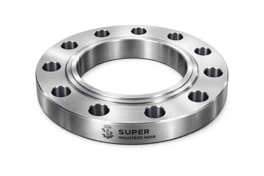
Role of ANSI B16.47 Flanges in Large-Diameter Piping Systems
ANSI B16.47 Flanges are engineered for large-bore piping systems (NPS 26” to 60”) where pressure containment, structural stability, and maintainability are critical. These flanges are deployed in systems where welded joints alone are insufficient due to operational, inspection, or maintenance constraints.
Large-diameter pipelines operate under combined loading conditions:
- Internal pressure
- External mechanical loads
- Thermal expansion
- Environmental stressors
In such systems, flanged joints provide controlled disassembly capability, enabling inspection, maintenance, and component replacement without cutting or re-welding.
Primary Application Sectors
Oil & Gas Transmission Pipelines
Used in cross-country pipelines for crude oil, natural gas, and multiphase fluids where large diameters reduce frictional losses and improve flow efficiency.
Refineries
Installed in process units such as distillation columns, hydrocrackers, and storage transfer systems where periodic shutdown inspection is required.
Offshore Platforms
Applied in topside modules and subsea tie-ins where modular assembly and disassembly are essential due to logistical constraints.
Power Generation Plants
Used in cooling water systems, steam exhaust systems, and flue gas ducting involving large flow volumes.
Petrochemical Facilities
Installed in bulk fluid transfer lines handling hydrocarbons, chemicals, and gases under varying pressure and temperature conditions.
LNG Terminals
Used in cryogenic and regasification systems requiring dimensional stability and leak-tight performance.
Water Transmission Systems
Applied in municipal and industrial water pipelines, desalination plants, and flood control systems.
Why Large-Diameter Flanged Joints Are Preferred
1. Maintenance Accessibility
Flanged joints allow non-destructive disassembly, essential for:
- Internal inspection
- Gasket replacement
- Valve and equipment maintenance
2. Inspection-Critical Systems
Used in systems governed by:
- Periodic NDT inspection
- Regulatory compliance
- Shutdown-based maintenance schedules
3. High-Pressure Large Bore Pipelines
Ensure:
- Controlled gasket sealing
- Uniform load distribution
- Resistance to leakage under pressure fluctuations
4. Alignment Flexibility
Allow minor alignment corrections during installation, unlike welded joints which require precise fit-up.
2. Technical Definition
Definition of ANSI B16.47 Flanges
ANSI B16.47 Flanges are:
- Pressure-retaining flanged connections
- Designed for Nominal Pipe Size (NPS) 26” to 60”
- Governed by ASME B16.47 standard
- Applicable where ASME B16.5 dimensional limits are exceeded
They are used in conjunction with:
- Bolting systems (ASTM A193/A194)
- Gaskets (ASME B16.20 / B16.21)
- Large-diameter piping systems
Series Classification
ANSI B16.47 Flanges are divided into two dimensional series:
Series A (Derived from MSS SP-44)
Characteristics:
- Larger bolt circle diameter
- Higher number of bolts
- Larger bolt diameters
- Greater flange thickness
- Higher structural rigidity
- Increased weight
Engineering Implication:
- Suitable for high-stress, high-load applications
- Preferred in critical service pipelines
Series B (Derived from API 605)
Characteristics:
- Smaller bolt circle diameter
- Fewer bolts
- Smaller bolt sizes
- Reduced flange thickness
- Lower weight
Engineering Implication:
- Economical for moderate pressure systems
- Used where load conditions are less severe
Dimensional Differences: Series A vs Series B
| Parameter | Series A | Series B |
|---|---|---|
| Bolt Circle Diameter | Larger | Smaller |
| Number of Bolts | Higher | Lower |
| Bolt Size | Larger | Smaller |
| Flange Thickness | Higher | Lower |
| Weight | Higher | Lower |
| Structural Strength | Higher | Moderate |
Engineering Selection Consideration
Selection between Series A and Series B depends on:
- Design pressure
- External loading conditions
- Weight constraints
- Cost considerations
- Compatibility with existing systems
Super Industries
Global Manufacturer of Heavy & Custom Engineered Fasteners & Flanges
3. Engineering & Sealing Principle
Fundamental Sealing Mechanism
ANSI B16.47 Flanges achieve sealing through:
Bolt preload → gasket compression → sealing stress → leak prevention
Bolt Preload Mechanics
When bolts are tightened:
- Tensile force is induced in the bolt
- Compressive force is applied on the gasket
- Flange faces are drawn together
The preload must:
- Exceed internal pressure-induced separation force
- Maintain gasket compression under operating conditions
Gasket Compression Theory
Gasket sealing requires:
- Initial seating stress → to deform gasket surface
- Operating stress retention → to maintain seal under pressure and temperature
Key parameters:
- Gasket factor (m)
- Minimum seating stress (y)
Flange Face Contact Stress
Contact stress must be:
- Uniform across gasket surface
- Above minimum sealing stress
- Below material yield limits
Improper stress distribution leads to:
- Leakage paths
- Gasket failure
- Bolt relaxation
Leakage Prevention Mechanisms
Leak prevention depends on:
- Adequate bolt preload
- Proper gasket selection
- Controlled surface finish
- Flange rigidity
Facing Types
Raised Face (RF)
- Most commonly used
- Provides controlled gasket seating area
- Suitable for soft gaskets
Ring Type Joint (RTJ)
- Metal-to-metal sealing with ring gasket
- Used in:
- High-pressure systems
- High-temperature service
- Critical hydrocarbon applications
Gasket Seating vs Operating Stress
| Condition | Requirement |
|---|---|
| Initial Installation | High seating stress required |
| Operating Condition | Stress must remain above leakage threshold |
Loss of stress occurs due to:
- Thermal expansion
- Creep relaxation
- Bolt relaxation
Bolt Stress vs Internal Pressure Interaction
Internal pressure generates:
- Axial separation force
- Radial expansion force
Bolt preload must counteract:
- Hydrostatic end force
- Gasket blowout tendency
Flange Rotation & Deflection
Under load:
- Flanges tend to rotate outward
- Outer edge experiences higher stress
- Inner edge may lose contact pressure
Design must ensure:
- Controlled rotation
- Adequate stiffness
- Uniform gasket compression
4. Pressure & Load Engineering
Pressure Classes in ANSI B16.47 Flanges
- Class 75
- Class 150
- Class 300
- Class 400
- Class 600
- Class 900
These classes define:
- Maximum allowable pressure
- Temperature-pressure relationship
Internal Pressure Loading
Internal pressure produces:
- Axial force trying to separate flanges
- Hoop stress in pipe
- Radial stress on flange faces
External Loads
Pipe Weight
Acts as bending load on flange joint
Thermal Expansion
Causes:
- Axial displacement
- Additional stress on bolts and flange
Wind & Seismic Forces
Relevant for:
- Above-ground pipelines
- Offshore structures
Flange Design Stress Limits
Controlled by:
- Material yield strength
- Allowable stress (ASME Section II)
- Design safety factors
Gasket Stress Retention
Critical for long-term sealing:
- Must maintain compression over time
- Affected by:
- Temperature
- Pressure cycles
- Material creep
Fatigue Considerations
Cyclic loading leads to:
- Bolt fatigue
- Flange cracking
- Gasket degradation
Applicable in:
- Pulsating flow systems
- Compressor discharge lines
- Offshore installations
Dimensional & Design Logic
Key Dimensional Parameters
Bolt Circle Diameter (BCD)
Defines bolt placement and load distribution
Number of Bolts
Determines:
- Load sharing
- Gasket compression uniformity
Bolt Size & Length
Must satisfy:
- Tensile strength requirements
- Engagement length criteria
Flange Thickness
Controls:
- Structural rigidity
- Resistance to bending
- Load distribution
Hub Dimensions (For Weld Neck Flanges)
Provide:
- Stress transition between pipe and flange
- Reduction in stress concentration
Facing Types
- Raised Face (RF)
- Flat Face (FF)
- Ring Type Joint (RTJ)
Dimensional Control Parameters
Flatness Tolerance
Ensures uniform gasket seating
Parallelism
Prevents uneven bolt loading
Concentricity
Ensures alignment with pipe axis
Surface Roughness (Ra Values)
Typical values:
- RF: 3.2 – 6.3 µm
- RTJ grooves: precision machined as per standard
Engineering Importance of Dimensional Control
Deviation leads to:
- Uneven gasket compression
- Bolt overstressing
- Leakage risk
5. Applicable Standards
Primary Governing Standard — ASME B16.47
ANSI B16.47 Flanges are designed, manufactured, and inspected in accordance with:
- ASME B16.47
- Covers large-diameter flanges (NPS 26” to 60”)
- Defines:
- Dimensions
- Pressure-temperature ratings
- Tolerances
- Marking requirements
- Divided into:
- Series A (MSS SP-44 origin)
- Series B (API 605 origin)
This standard ensures interchangeability, dimensional consistency, and pressure integrity across global EPC projects.
Boundary Standard — ASME B16.5
- Covers flanges up to NPS 24”
- Used as a design and selection reference boundary
- Ensures continuity when transitioning from smaller to large-diameter piping systems
Series-Origin Standards
MSS SP-44
- Basis for Series A flanges
- Originally developed for:
- High-pressure transmission pipelines
- Emphasizes:
- Increased bolt count
- Higher structural rigidity
API 605
- Basis for Series B flanges
- Designed for:
- Refinery and process piping systems
- Focus on:
- Reduced weight
- Dimensional compatibility with legacy systems
Material Standards (ASTM)
Material selection for ANSI B16.47 Flanges is governed by ASTM specifications:
Carbon Steel
- ASTM A105 — Forged carbon steel for ambient and elevated temperature
- ASTM A350 LF2 — Low-temperature carbon steel with impact toughness
Stainless Steel
- ASTM A182 F304 — General corrosion resistance
- ASTM A182 F316 — Enhanced resistance to chlorides and chemicals
Alloy Steel
- ASTM A182 F11 — Chromium-molybdenum alloy for moderate temperature
- ASTM A182 F22 — Higher temperature and pressure capability
Duplex / Super Duplex
- High strength + corrosion resistance
- Suitable for:
- Offshore
- Marine
- Chloride environments
EN / DIN Equivalents
For international project compatibility:
| ASTM Grade | EN Equivalent | DIN Equivalent |
|---|---|---|
| A105 | EN 10222-2 P250GH | DIN 1.0460 |
| LF2 | EN 10222-4 P215NL | DIN 1.0425 |
| F304 | EN 10222-5 X5CrNi18-10 | DIN 1.4301 |
| F316 | EN 10222-5 X5CrNiMo17-12-2 | DIN 1.4401 |
Standards Mapping to Engineering Selection
| Requirement | Standard Reference |
|---|---|
| Dimensional compliance | ASME B16.47 |
| Pressure-temperature rating | ASME B16.47 + ASME Section II |
| Material properties | ASTM standards |
| Inspection & testing | ASME Section V / ASTM |
| Certification | EN 10204 |
6. Material & Grade Options
Material selection is driven by:
- Operating pressure
- Temperature range
- Corrosive environment
- Mechanical loading
- Design life requirements
Carbon Steel Flanges
ASTM A105
- Standard forged carbon steel
- Suitable for:
- Ambient to moderate temperatures
- Hydrocarbon service
- Limitations:
- Not suitable for low-temperature brittle conditions
ASTM A350 LF2
- Low-temperature carbon steel
- Improved notch toughness
- Suitable for:
- Sub-zero applications
- LNG systems
Stainless Steel Flanges
ASTM A182 F304
- Austenitic stainless steel
- Good corrosion resistance
- Used in:
- Water systems
- Mild chemical environments
ASTM A182 F316
- Contains molybdenum
- Enhanced resistance to:
- Chlorides
- Chemical corrosion
- Suitable for:
- Marine environments
- Chemical processing
Alloy Steel Flanges
ASTM A182 F11
- Chromium-molybdenum alloy
- Used in:
- Moderate temperature service
- Power plants
ASTM A182 F22
- Higher Cr-Mo content
- Suitable for:
- High temperature
- High pressure
- Steam systems
Duplex / Super Duplex Stainless Steel
Characteristics:
- Dual-phase microstructure (austenite + ferrite)
- Higher strength than austenitic steels
- Superior resistance to:
- Stress corrosion cracking
- Pitting corrosion
Applications:
- Offshore platforms
- Seawater systems
- Aggressive chemical environments
Material Comparison Table
| Grade | Yield Strength (MPa) | Tensile Strength (MPa) | Temperature Range | Corrosion Resistance | Typical Applications |
|---|---|---|---|---|---|
| A105 | ~250 | 485–620 | -29°C to 425°C | Low | Oil & gas pipelines |
| LF2 | ~250 | 485–620 | -46°C to 345°C | Low | LNG, low-temp service |
| F304 | ~205 | 515–720 | -196°C to 870°C | Moderate | Water, chemical |
| F316 | ~205 | 515–720 | -196°C to 870°C | High | Marine, chemical |
| F11 | ~275 | 415–585 | Up to 540°C | Moderate | Power plants |
| F22 | ~415 | 585–760 | Up to 600°C | Moderate | High-temp steam |
| Duplex | ~450 | 620–880 | -50°C to 300°C | Very High | Offshore systems |
Engineering Considerations in Material Selection
Temperature Limits
- Carbon steel → limited at low temperature
- Stainless steel → wide temperature range
- Alloy steel → high temperature capability
Corrosion Resistance
- Carbon steel → requires coating
- Stainless steel → inherent corrosion resistance
- Duplex → superior in chloride environments
Pressure Suitability
- High-strength materials allow:
- Reduced thickness
- Improved load capacity
7. Heat Treatment
Heat treatment ensures:
- Required mechanical properties
- Controlled microstructure
- Stress relief
Normalizing
Process:
- Heating above critical temperature
- Air cooling
Purpose:
- Grain refinement
- Uniform structure
- Improved toughness
Quenching & Tempering
Process:
- Rapid cooling (quenching)
- Controlled reheating (tempering)
Purpose:
- Increase strength
- Improve hardness
- Maintain ductility
Applicable to:
- Alloy steels (F11, F22)
Solution Annealing (Stainless Steel)
Process:
- Heating to high temperature
- Rapid quenching
Purpose:
- Dissolve carbides
- Restore corrosion resistance
Stress Relieving
Process:
- Heating below transformation temperature
Purpose:
- Reduce residual stresses from:
- Forging
- Machining
Hardness Control
Typical ranges:
| Material | Hardness (HB) |
|---|---|
| A105 | 120–187 |
| LF2 | 120–200 |
| F11/F22 | 130–220 |
| Stainless Steel | ≤ 200 |
Impact Testing (Charpy V-Notch)
Required for:
- Low-temperature service (LF2)
- Critical applications
Measures:
- Energy absorption capacity
- Resistance to brittle fracture
Manufacturing Process
ANSI B16.47 Flanges are manufactured through controlled processes ensuring dimensional accuracy and structural integrity.
Step 1: Raw Material Inspection
- Verification of:
- Chemical composition
- Mechanical properties
- Traceability through:
- Heat numbers
- Mill test certificates
Step 2: Forging / Ring Rolling
Open Die Forging
- Used for large flanges
- Provides:
- Grain flow alignment
- Structural strength
Ring Rolling
- Produces:
- Uniform grain structure
- Controlled dimensions
Step 3: Heat Treatment
- Applied as per material grade
- Ensures:
- Mechanical property compliance
- Stress relief
Step 4: CNC Machining
Includes:
- Outer diameter machining
- Bore machining
- Facing operations
Ensures:
- Dimensional precision
- Surface finish control
Step 5: Facing Machining
- RF serration machining
- RTJ groove cutting
Critical for:
- Gasket sealing performance
Step 6: Bolt Hole Drilling
- CNC drilling for:
- Positional accuracy
- Angular precision
Tolerance control:
- Bolt hole alignment
- Pitch circle accuracy
Step 7: Marking & Traceability
Includes:
- Heat number
- Material grade
- Size and pressure class
- Standard reference (ASME B16.47)
Large-Diameter Machining Challenges
- Handling heavy components
- Maintaining flatness across large surfaces
- Controlling distortion during machining
- Ensuring concentricity
Dimensional Control Discipline
Critical checks:
- Bore alignment
- Face flatness
- Bolt hole positioning
- Thickness uniformity
Surface Finish Options
Surface treatment is applied based on:
- Environmental exposure
- Corrosion risk
- Project specifications
Available Surface Finishes
Anti-Rust Oil Coating
- Temporary protection
- Used during storage and transport
Zinc Plating
- Corrosion protection
- Suitable for:
- Mild environments
Hot-Dip Galvanizing
- Thick zinc coating
- Suitable for:
- Outdoor and marine environments
PTFE Coating
- Chemical resistance
- Low friction surface
Black Oxide
- Minimal corrosion resistance
- Used for indoor applications
Passivation (Stainless Steel)
- Enhances oxide layer
- Improves corrosion resistance
Surface Roughness (Ra Values)
| Facing Type | Surface Roughness (Ra) |
|---|---|
| Raised Face (RF) | 3.2 – 6.3 µm |
| Smooth Finish | ≤ 3.2 µm |
| RTJ Groove | Precision machined |
Serrated Finish Requirements
- Concentric or spiral serrations
- Ensures:
- Gasket grip
- Leakage prevention
8. Dimensional Reference Tables (Indicative Engineering Data)
The following tables provide representative dimensional logic for ANSI B16.47 Flanges. Final dimensions shall always be verified against ASME B16.47 tables (Series A / Series B) for project-specific compliance.
A. Dimension Table (Sample — Series A)
| NPS (in) | Class | Bolt Size (in) | No. of Bolts | Bolt Circle Dia (mm) | Flange Thickness (mm) |
|---|---|---|---|---|---|
| 26 | 150 | 1-1/2 | 28 | 1245 | 69 |
| 30 | 150 | 1-1/2 | 32 | 1397 | 73 |
| 36 | 150 | 1-5/8 | 36 | 1651 | 79 |
| 42 | 150 | 1-3/4 | 40 | 1905 | 86 |
| 48 | 150 | 1-3/4 | 44 | 2159 | 92 |
| 54 | 150 | 2 | 48 | 2413 | 98 |
| 60 | 150 | 2 | 52 | 2667 | 105 |
Engineering Observations
- Increase in NPS results in:
- Higher bolt count
- Larger bolt diameters
- Increased flange thickness
- Designed to:
- Maintain gasket compression
- Resist bending and rotation
B. Pressure Rating Table (ASME B16.47 Basis)
Pressure ratings depend on:
- Material group
- Temperature
- Pressure class
Example — Carbon Steel (A105)
| Class | Pressure at 38°C (bar) | Pressure at 200°C (bar) | Pressure at 400°C (bar) |
|---|---|---|---|
| 75 | 5.2 | 4.5 | 2.6 |
| 150 | 19.6 | 15.6 | 10.2 |
| 300 | 51.1 | 40.0 | 26.6 |
| 400 | 68.1 | 53.3 | 35.4 |
| 600 | 102.1 | 80.0 | 53.3 |
| 900 | 153.2 | 120.0 | 80.0 |
Temperature Derating
- Allowable pressure reduces with temperature increase
- Governed by:
- Material allowable stress (ASME Section II)
C. Torque Chart (ASTM A193 B7 Bolting)
Torque values depend on:
- Bolt diameter
- Lubrication condition
- Desired preload
Torque Values (Indicative)
| Bolt Size (in) | Torque (Nm) — Lubricated | Torque (Nm) — Dry |
|---|---|---|
| 1″ | 900 | 1200 |
| 1-1/4″ | 1600 | 2100 |
| 1-1/2″ | 2800 | 3600 |
| 1-3/4″ | 4500 | 5800 |
| 2″ | 7000 | 9000 |
| 2-1/2″ | 12000 | 15000 |
Engineering Notes
- Lubrication reduces friction → improves preload accuracy
- Torque values are approximate; actual preload must be verified through:
- Bolt stress calculation
- Tensioning methods (hydraulic tensioners for large diameters)
D. Preload Calculation Guide
1. Bolt Stress Formula
Bolt stress is defined as:
![\[\sigma = \frac{F}{A}\]](https://superindustriesindia.in/wp-content/ql-cache/quicklatex.com-d820ba2a7649df33c4e35cab55485169_l3.png "Rendered by QuickLaTeX.com")
Where:
- σ = Bolt stress
- F = Axial preload force
- A = Tensile stress area
2. Torque–Preload Relationship
![\[T = K \cdot F \cdot d\]](https://superindustriesindia.in/wp-content/ql-cache/quicklatex.com-637ae80de10d14a2f4d17cc6dfd9f1fa_l3.png "Rendered by QuickLaTeX.com")
Where:
- T = Applied torque
- K = Nut factor (typically 0.15–0.25)
- F = Preload force
- d = Nominal bolt diameter
3. Axial Separation Force
Internal pressure creates a separating force:
![\[F_p = P \cdot A_g\]](https://superindustriesindia.in/wp-content/ql-cache/quicklatex.com-ae46fa16e7ec79c305ba6aa1355605a9_l3.png "Rendered by QuickLaTeX.com")
Where:
- Fp = Pressure-induced force
- P = Internal pressure
- Ag = Effective gasket area
4. Engineering Condition for Leak Prevention
For sealing integrity:
Bolt preload force > Internal separation force
5. Sample Calculation
Given:
- Pressure (P) = 20 MPa
- Gasket area (Ag) = 0.5 m²
- Bolt diameter = 36 mm
- Nut factor (K) = 0.2
Step 1: Separation Force
Fp = 20 × 10⁶ × 0.5 = 10,000,000 N
Step 2: Required Bolt Preload
Assume safety factor = 1.5
Required preload:
F = 1.5 × 10,000,000 = 15,000,000 N
Step 3: Torque Calculation
T = 0.2 × 15,000,000 × 0.036
T = 108,000 Nm
Engineering Interpretation
- Large-diameter flanges require:
- High bolt preload
- Controlled tightening procedures
- Hydraulic bolt tensioning is preferred over torque for accuracy
E. Mechanical Properties Table
| Material | Yield Strength (MPa) | Tensile Strength (MPa) | Elongation (%) | Hardness (HB) | Impact (J) |
|---|---|---|---|---|---|
| A105 | ≥250 | 485–620 | ≥22 | 120–187 | — |
| LF2 | ≥250 | 485–620 | ≥22 | 120–200 | ≥27 @ -46°C |
| F304 | ≥205 | 515–720 | ≥30 | ≤200 | — |
| F316 | ≥205 | 515–720 | ≥30 | ≤200 | — |
| F11 | ≥275 | 415–585 | ≥20 | 130–200 | — |
| F22 | ≥415 | 585–760 | ≥20 | 140–220 | — |
| Duplex | ≥450 | 620–880 | ≥25 | ≤290 | — |
F. Corrosion Resistance Table
| Material | Marine | Acidic | Hydrocarbon | High Humidity |
|---|---|---|---|---|
| Carbon Steel | Low | Low | Good | Low |
| SS304 | Moderate | Moderate | Good | Good |
| SS316 | High | High | Good | High |
| Alloy Steel | Moderate | Low | Good | Moderate |
| Duplex | Very High | High | Excellent | Very High |
9. Inspection & Quality Control
Inspection of ANSI B16.47 Flanges is performed to ensure:
- Pressure integrity
- Material compliance
- Dimensional accuracy
- Traceability
Material Verification
PMI (Positive Material Identification)
- Confirms alloy composition
- Ensures correct material grade
Non-Destructive Testing (NDT)
Ultrasonic Testing (UT)
- Detects internal defects
- Ensures forging integrity
Magnetic Particle Inspection (MPI)
- Detects surface and near-surface cracks
- Applicable to ferromagnetic materials
Dye Penetrant Inspection (DPI)
- Detects surface discontinuities
- Used for stainless steel
Dimensional Inspection
Checks include:
- Outer diameter
- Bore diameter
- Bolt circle diameter
- Bolt hole alignment
- Thickness
- Facing geometry
Hardness Testing
- Ensures compliance with:
- Material specifications
- Prevents:
- Over-hardening (brittleness)
- Under-hardening (low strength)
Hydrostatic Testing (If Applicable)
- Verifies pressure containment capability
- Typically applied in assembled systems
Third-Party Inspection (TPI)
Inspection agencies:
- Client-approved inspectors
- Independent verification bodies
Scope:
- Witnessing tests
- Reviewing documentation
- Final inspection release
Certification
EN 10204 3.1
- Manufacturer test certificate
- Confirms:
- Chemical composition
- Mechanical properties
EN 10204 3.2
- Third-party validated certificate
- Required for:
- Critical EPC projects
- Offshore and high-risk applications
Traceability System
Maintained through:
- Heat number stamping
- Batch tracking
- Material certificates
- Inspection records
Quality Control Objectives
- Eliminate dimensional deviation
- Ensure gasket sealing reliability
- Maintain pressure integrity under operating conditions
10. Industries Served
ANSI B16.47 Flanges are deployed across sectors where large-diameter, pressure-retaining joints are required under controlled engineering conditions.
Oil & Gas Transmission Pipelines
Used in:
- Cross-country crude oil pipelines
- Natural gas transmission systems
- Gathering and distribution networks
Engineering requirements:
- High-pressure integrity
- Resistance to cyclic loading
- Field assembly and maintenance capability
Flanges enable:
- Sectional isolation
- Inline inspection (pigging access points)
- Maintenance without pipeline cutting
Refineries
Installed in:
- Process piping systems
- Crude and vacuum distillation units
- Hydroprocessing and catalytic units
Operational requirements:
- High temperature and pressure resistance
- Chemical compatibility
- Shutdown inspection accessibility
Petrochemical Plants
Applications include:
- Bulk chemical transfer lines
- Polymer and intermediate product pipelines
- Utility systems (steam, cooling water)
Material selection is driven by:
- Corrosion resistance
- Chemical compatibility
- Process temperature
Power Generation
Used in:
- Cooling water systems
- Condenser lines
- Flue gas and exhaust systems
Key considerations:
- Thermal expansion loads
- Large volumetric flow
- Structural support integration
LNG Terminals
Installed in:
- Cryogenic pipelines
- Regasification systems
- Storage tank connections
Requirements:
- Low-temperature toughness
- Leak-tight sealing
- Dimensional stability
Offshore & Marine Systems
Used in:
- Offshore platforms
- Subsea-to-topside connections
- Seawater handling systems
Critical factors:
- Corrosion resistance (chloride exposure)
- Fatigue resistance
- Weight optimization
Water Transmission & Infrastructure
Applications:
- Municipal water supply pipelines
- Desalination plants
- Flood control systems
Design considerations:
- Large-diameter flow efficiency
- Corrosion protection
- Ease of installation and maintenance
11. Export Capability & Global Supply
Super Industries supplies ANSI B16.47 Flanges for international EPC projects, aligned with documentation, logistics, and compliance requirements.
Regions Served
- United States
- European Union
- Middle East (UAE, Saudi Arabia, Qatar, Kuwait)
- Southeast Asia
- Africa (project-based supply)
Packaging for Large-Diameter Flanges
Due to size and weight constraints:
- Wooden crates (ISPM-15 compliant)
- Steel-reinforced palletization
- Individual flange protection:
- Plastic caps for faces
- Edge protectors
- Anti-corrosion wrapping
Export Documentation
Supplied documentation includes:
- Commercial Invoice
- Packing List
- Certificate of Origin
- Mill Test Certificates (EN 10204 3.1 / 3.2)
- Inspection Reports
- Heat Treatment Charts
- NDT Reports
Project Logistics Handling
- Coordination with EPC contractors
- Lot-wise dispatch based on project schedule
- Handling of heavy-lift cargo
- Containerization or break-bulk shipment
Compliance Documentation
Ensures alignment with:
- ASME B16.47
- ASTM material standards
- Project specifications
- Third-party inspection requirements
12. Procurement & Installation Guidelines
This section is structured for EPC contractors, site engineers, and commissioning teams.
A. Pre-Installation Checks
Verify:
- Flange size, class, and rating
- Material grade and certification
- Facing condition (RF / RTJ)
- Bolt and gasket compatibility
Inspection points:
- Surface damage
- Corrosion or contamination
- Dimensional compliance
B. Gasket Installation Practices
- Select gasket as per:
- Pressure class
- Temperature
- Fluid compatibility
- Ensure:
- Clean seating surfaces
- Proper alignment
- No reuse of compressed gaskets
C. Bolt Tightening Sequence
Use cross-tightening (star pattern):
- Initial snug tightening
- Intermediate torque (30–50%)
- Final torque (100%)
Objective:
- Uniform gasket compression
- Prevention of flange rotation
D. Torque Application Stages
Typical tightening sequence:
- Stage 1 → 30% of final torque
- Stage 2 → 60% of final torque
- Stage 3 → 100% torque
- Stage 4 → Final circular pass
E. Lubrication Requirements
Apply lubricant to:
- Bolt threads
- Nut bearing surfaces
Purpose:
- Reduce friction variability
- Improve preload accuracy
F. Re-Torque Requirements
Re-tightening may be required:
- After initial pressurization
- After thermal cycling
Conditions:
- Only when system is depressurized
- Follow project procedures
G. Field Inspection Checkpoints
Verify:
- Bolt tension consistency
- Gasket seating condition
- Alignment of flanges
- Absence of leakage during hydrotest
H. Storage & Handling
Storage
- Keep in dry, covered area
- Avoid direct ground contact
- Maintain protective coatings
Handling
- Use lifting equipment for large diameters
- Avoid:
- Dropping
- Edge damage
- Face scratching
13. Custom Engineering Capabilities
Super Industries manufactures ANSI B16.47 Flanges with project-specific customization, aligned with EPC requirements.
Non-Standard Diameters
- Custom sizes beyond standard NPS range
- Designed as per client drawings
Custom Drilling Patterns
- Non-standard bolt hole configurations
- Matching legacy or retrofit systems
Special Thickness Flanges
- Increased thickness for:
- High external loads
- Structural reinforcement
RTJ Groove Customization
- Machining as per:
- API ring numbers
- Project-specific tolerances
Project-Specific Marking
Includes:
- Heat number
- Purchase order reference
- Tag numbers
- Client-specific identification
Engineering Summary
ANSI B16.47 Flanges are critical components in large-diameter piping systems, designed to:
- Maintain pressure integrity
- Enable controlled assembly and disassembly
- Support mechanical and thermal loads
- Ensure leak-tight performance
Engineering performance depends on:
- Correct selection (Series A / Series B)
- Material suitability
- Controlled manufacturing
- Accurate bolt preload
- Proper installation practices
Final Technical Positioning
This document establishes ANSI B16.47 Flanges as:
- ASME-compliant pressure-retaining components
- Suitable for large-diameter, high-load applications
- Compatible with EPC procurement and inspection protocols
Super Industries manufactures these flanges with:
- Controlled dimensional tolerances
- Traceable material systems
- Documented inspection procedures
- Compliance with global project requirements