
THREADED FLANGES
Global Manufacturer of Heavy & Custom Engineered Fasteners for Oil & Gas, Power & EPC Contractors.
1. Industry Context & System Relevance
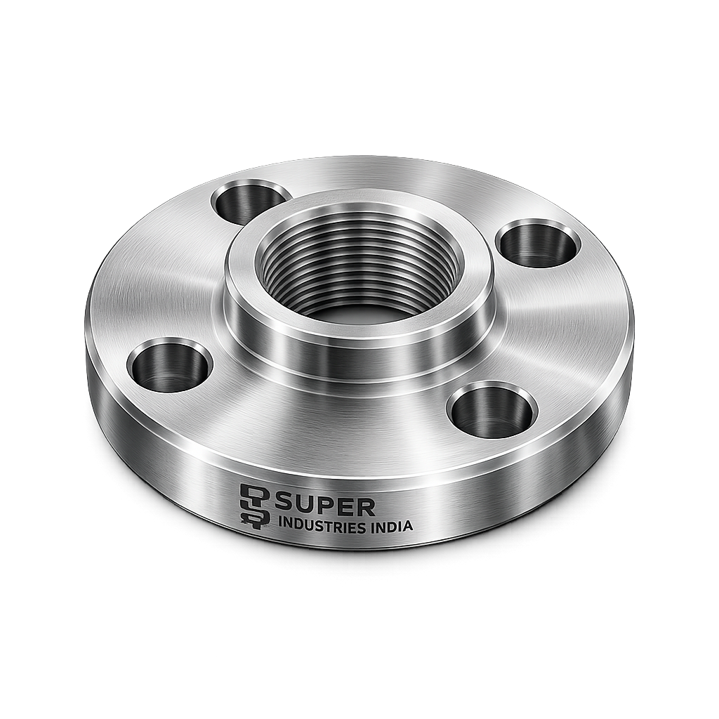
In industrial piping systems, Threaded Flanges serve as a mechanically assembled pressure-connection interface designed for joining threaded pipe ends, valves, strainers, instrumentation branches, and auxiliary equipment without welding.
These flanges are primarily selected where:
- welding is operationally restricted
- hot work permits are difficult to obtain
- line modifications are expected during maintenance
- small-bore piping requires fast assembly
- temporary or modular installations are preferred
Threaded flange connections remain widely used across:
- oil & gas gathering lines
- refinery utility systems
- power plant auxiliary services
- petrochemical secondary lines
- compressed air systems
- firefighting and hydrant networks
- instrument impulse lines
- water and utility piping
Their principal advantage lies in providing a pressure-retaining joint without fusion welding, making them particularly suitable for low-to-medium pressure services and hazardous areas.
Application in Oil & Gas Systems
Within upstream and downstream facilities, threaded flange assemblies are commonly applied in:
- chemical injection lines
- fuel oil transfer systems
- instrument tubing transitions
- low-pressure hydrocarbon services
- nitrogen and air utility lines
- drain and vent headers
In brownfield modifications and shutdown maintenance, threaded flanges are frequently preferred because they reduce:
- welding setup time
- welder qualification dependency
- NDT requirements for field joints
- post-weld heat treatment concerns
This directly improves maintenance turnaround efficiency.
Role in Refineries & Petrochemical Plants
Refineries often operate under strict hot-work controls due to hydrocarbon presence.
In such areas, Threaded Flanges provide an effective connection method for:
- temporary bypass lines
- analyzer connections
- steam tracing auxiliaries
- sample take-off points
- low-pressure chemical circulation loops
Because no arc welding is required, installation risk in volatile atmospheres is significantly reduced.
Use in Power Plants
Thermal and combined-cycle power plants utilize threaded flange systems for:
- service water lines
- fuel gas auxiliaries
- instrument air systems
- drain headers
- lubrication oil piping
However, use in high-temperature steam mains is generally avoided due to stress concentration risks associated with threaded joints.
Fire Protection & Utility Systems
Threaded flange assemblies are extensively used in:
- sprinkler systems
- fire water ring mains
- jockey pump connections
- hydrant branches
- municipal water services
These services typically operate at moderate pressure ranges where threaded joints remain practical and code-compliant.
Why Threaded Connections Are Used
The engineering logic behind using threaded flanges is primarily based on service practicality.
A. Low-Pressure Systems
For systems operating below the threshold where welded joints become structurally necessary, threaded flanges offer sufficient sealing and load resistance.
Typical applications include:
- Class 150
- Class 300
- limited Class 600 services
- specialized Class 1500 small-bore lines
depending on medium, temperature, and cyclic loading.
B. Non-Weld Applications
Threaded flange joints are specified where welding is undesirable because of:
- flammable environment
- material metallurgical sensitivity
- field accessibility constraints
- maintenance downtime limitations
This is especially relevant for retrofit projects.
C. Hazardous Environments (No Hot Work Zones)
Many hydrocarbon plants impose restricted zones where hot work is prohibited.
In such conditions, threaded connections enable safe mechanical installation.
Examples include:
- offshore platforms
- gas compression stations
- solvent handling plants
- tank farm utilities
D. Maintenance-Friendly Installations
Since the connection is detachable, threaded flanges support:
- valve replacement
- inline equipment servicing
- branch isolation
- periodic inspection access
This makes them suitable for maintenance-intensive systems.
Comparison: Threaded vs Welded vs Other Flange Types
| Connection Type | Welding Required | Pressure Capability | Maintenance Ease | Leak Risk |
|---|---|---|---|---|
| Threaded Flanges | No | Low to Medium | High | Moderate |
| Slip-On Flanges | Yes | Medium | Medium | Low |
| Weld Neck Flanges | Yes | High | Medium | Very Low |
| Socket Weld | Yes | Medium to High | Medium | Low |
Threaded vs Weld Neck
A weld neck flange transfers axial and bending loads through a tapered hub and butt weld.
A threaded flange transfers load through:
- thread shear
- flank compression
- sealing interference
Therefore, threaded flanges are generally less suitable for:
- high vibration systems
- thermal cycling services
- high-pressure steam lines
Super Industries
Global Manufacturer of Heavy & Custom Engineered Fasteners & Flanges
2. Technical Definition
A Threaded Flange is an internally threaded flange fitting designed to mate with an externally threaded pipe end, creating a pressure-retaining joint without welding.
It is also commonly referred to as:
- screwed flange
- female threaded flange
- threaded pipe flange
The internal bore contains precision-machined threads matching the pipe standard.
Construction Definition
The flange consists of:
- flange face
- bolt circle
- hub section
- internally threaded bore
The pipe is rotated into the flange bore until full thread engagement is achieved.
No Welding Required
This is the defining engineering characteristic.
The joint relies on:
- mechanical thread engagement
- torque-induced interference
- thread sealant integrity
rather than welded fusion.
This significantly simplifies field assembly.
Thread Standards
A. NPT – National Pipe Thread
The most widely used standard in industrial piping is:
ASME B1.20.1 – NPT
NPT threads are tapered.
This taper creates progressive interference as the pipe advances into the flange.
The sealing is achieved through:
- flank pressure
- deformation at thread crests
- sealant filling micro-gaps
B. BSPT / BSPP
For export markets, threaded flanges may also be supplied in:
- BSPT – British Standard Pipe Taper
- BSPP – British Standard Pipe Parallel
These are frequently used in:
- Europe
- Middle East
- Southeast Asia
Tapered vs Parallel Threads
| Thread Type | Geometry | Sealing Method |
|---|---|---|
| Tapered | Conical | Interference sealing |
| Parallel | Straight | Gasket / sealant dependent |
Tapered threads provide better inherent sealing behavior.
Parallel threads require greater dependence on sealants or secondary sealing faces.
3. Engineering & Sealing Principle
The sealing performance of threaded flanges depends on the mechanics of thread engagement.
Thread Engagement Mechanics
As the male threaded pipe enters the flange thread, the helical surfaces begin load transfer.
The thread acts as a continuous inclined plane wrapped helically around the pipe axis.
Load is distributed along multiple engaged thread turns.
This creates:
- axial retention
- radial interference
- pressure containment
Helical Load Distribution
The load path follows the thread helix.
The first engaged threads generally experience the highest stress.
Typical load distribution:
- first thread: 30–35%
- second thread: 20–25%
- remaining threads: progressively lower
This is why machining accuracy is critical.
Sealing via Thread Interference
In tapered threads, sealing occurs through controlled interference.
As torque increases:
- flank contact pressure rises
- leak paths reduce
- thread root clearance decreases
Sealants such as:
- PTFE tape
- anaerobic thread compound
- liquid sealant paste
are used to block residual micro-leak paths.
Leak Paths in Threaded Joints
Potential leak paths include:
- crest-to-root clearances
- imperfect flank contact
- thread damage
- pitch mismatch
- galling in stainless steel
This makes thread tolerance control essential.
Role of Thread Pitch
Thread pitch directly affects:
- load transfer length
- sealing contact area
- assembly torque response
Finer pitch generally provides:
- improved sealing
- higher flank engagement area
but may be more sensitive to contamination.
Taper Angle Behavior
For NPT threads, taper is typically:
1 in 16 on diameter
This taper creates progressive sealing compression.
The further the pipe is tightened, the stronger the sealing interference becomes.
Engineering Limitations
Threaded flange systems must be evaluated carefully for service conditions.
A. Vibration
Continuous vibration can lead to:
- thread loosening
- flank wear
- fatigue crack initiation
- leakage
Hence, they are not preferred for rotating equipment discharge lines.
B. Pressure Constraints
Compared with welded joints, threaded connections have lower pressure reliability.
Pressure cycling increases risk of:
- sealant breakdown
- thread deformation
- leakage
C. Temperature Effects
Elevated temperatures can cause:
- thermal expansion mismatch
- relaxation of thread preload
- sealant degradation
This is particularly critical above 400°C service.
Super Industries
Global Manufacturer of Heavy & Custom Engineered Fasteners & Flanges
4. Applicable Standards (ASME / ASTM / DIN / ISO)
The design, manufacture, inspection, and application of Threaded Flanges are governed by internationally recognized standards that ensure dimensional uniformity, pressure integrity, and interchangeability across global EPC projects.
ASME Standards
ASME B16.5 – Pipe Flanges and Flanged Fittings
This is the primary governing standard for Threaded Flanges up to NPS 24.
It defines:
- pressure-temperature ratings (Class 150 to Class 1500)
- dimensional requirements (OD, thickness, bolt circle)
- facing types (RF, FF)
- tolerances
- marking requirements
Threaded flanges under ASME B16.5 are designated as:
- Class 150
- Class 300
- Class 600
- Class 900
- Class 1500
The standard ensures compatibility with mating flanges and bolting systems.
ASME B1.20.1 – Pipe Threads (NPT)
This standard governs:
- thread geometry
- taper angle (1:16)
- pitch
- thread engagement length
- gauge requirements
It ensures sealing capability through controlled interference.
ASTM Material Standards
Material selection for Threaded Flanges is governed by ASTM specifications, defining:
- chemical composition
- mechanical properties
- heat treatment requirements
- testing procedures
Common standards include:
- ASTM A105 – Carbon steel forgings
- ASTM A350 LF2 – Low-temperature carbon steel
- ASTM A182 – Alloy and stainless steel forgings
DIN / EN Standards
European projects often require compliance with:
- EN 1092-1 – Flanges and flanged connections
- DIN threaded flange equivalents (legacy systems)
Thread compatibility must be aligned with:
- BSPT / BSPP thread standards
ISO Thread Standards
ISO standards define:
- metric thread systems
- international compatibility
- tolerance classifications
Used primarily for non-NPT export requirements.
Standard Mapping to Engineering Selection
| Requirement | Governing Standard |
|---|---|
| Dimensional conformity | ASME B16.5 / EN 1092-1 |
| Thread geometry | ASME B1.20.1 / BSP standards |
| Material properties | ASTM A105 / A182 / A350 |
| Pressure rating | ASME B16.5 |
| Inspection & testing | ASTM + project specifications |
5. Material & Grade Options
Material selection for Threaded Flanges is based on:
- operating pressure
- service temperature
- corrosion environment
- fluid compatibility
- project specifications
Carbon Steel Grades
ASTM A105
- Standard material for ambient and moderate temperature services
- Suitable for oil & gas, water, and utility lines
- Good machinability and strength
ASTM A350 LF2
- Designed for low-temperature applications
- Improved toughness at sub-zero conditions
- Used in cryogenic and cold-weather installations
Stainless Steel Grades
ASTM A182 F304
- General corrosion resistance
- Suitable for water, mild chemicals, and food-grade systems
ASTM A182 F316
- Enhanced corrosion resistance due to molybdenum
- Suitable for marine, chemical, and chloride environments
Alloy Steel Grades
ASTM A182 F11
- Chromium-molybdenum alloy
- Suitable for moderate high-temperature services
ASTM A182 F22
- Higher creep resistance
- Used in elevated temperature and pressure systems
Duplex / Super Duplex Stainless Steel
- Higher strength than austenitic stainless steel
- Excellent resistance to stress corrosion cracking
- Used in offshore, subsea, and aggressive chemical environments
Material Comparison Table (Engineering Reference)
| Grade | Yield Strength (MPa) | Tensile Strength (MPa) | Temperature Range | Corrosion Resistance | Typical Industry Use |
|---|---|---|---|---|---|
| ASTM A105 | ~250 | ~485 | -29°C to 425°C | Low | Oil & gas, water lines |
| ASTM A350 LF2 | ~250 | ~485 | -46°C to 345°C | Low | Low-temperature systems |
| ASTM A182 F304 | ~205 | ~515 | -196°C to 870°C | Moderate | Food, water, chemicals |
| ASTM A182 F316 | ~205 | ~515 | -196°C to 870°C | High | Marine, chemical |
| ASTM A182 F11 | ~275 | ~515 | Up to ~540°C | Moderate | Power plants |
| ASTM A182 F22 | ~415 | ~585 | Up to ~600°C | Moderate | High-temp systems |
| Duplex SS | ~450 | ~620 | -50°C to 300°C | Very High | Offshore, subsea |
6. Heat Treatment Information
Heat treatment ensures that Threaded Flanges achieve required mechanical properties, dimensional stability, and metallurgical structure.
Normalizing
Applicable to carbon steel:
- refines grain structure
- improves uniformity
- enhances mechanical strength
Quenching & Tempering
Used for alloy steels:
- increases strength and toughness
- improves fatigue resistance
- reduces brittleness
Stress Relieving
Performed after machining:
- reduces residual stresses
- prevents distortion during service
- stabilizes dimensional accuracy
Solution Annealing (Stainless Steel)
- dissolves carbides
- restores corrosion resistance
- improves ductility
Rapid cooling prevents sensitization.
Hardness Control
Hardness is maintained within specified limits to:
- avoid brittle failure
- ensure machinability
- prevent thread galling
Impact Testing (Charpy V-Notch)
Required for low-temperature services:
- measures toughness
- ensures resistance to brittle fracture
7. Manufacturing Process
The production of Threaded Flanges follows a controlled sequence to ensure dimensional accuracy and pressure integrity.
Raw Material Inspection
Incoming material is verified for:
- chemical composition (via mill test certificate)
- mechanical properties
- traceability
Forging / Bar Stock Preparation
Flanges are produced by:
- open-die forging
- closed-die forging
- machining from rolled bar (small sizes)
Forging improves:
- grain flow alignment
- mechanical strength
- structural integrity
Rough Machining
Initial machining includes:
- outer diameter turning
- hub shaping
- bore preparation
Thread Machining
Critical stage involving:
- CNC threading or tapping
- precision control of pitch and taper
- adherence to ASME B1.20.1
Thread quality directly affects sealing performance.
Facing & Drilling
- flange face machining (RF/FF)
- bolt hole drilling
- surface finish control
Heat Treatment
Performed based on material grade:
- normalizing
- quenching & tempering
- solution annealing
Surface Finishing
Application of coatings based on project requirement.
Marking & Traceability
Each flange is marked with:
- material grade
- heat number
- pressure class
- manufacturer identification
Ensures full traceability.
Thread Accuracy Control
Threads are verified using:
- calibrated gauges
- pitch measurement tools
- taper verification
Gauge Inspection (Go / No-Go)
Thread acceptance is validated using:
- Go gauge → ensures proper engagement
- No-Go gauge → prevents oversize threads
This ensures field compatibility and sealing reliability.
Surface Finish Options
Surface protection is selected based on environmental exposure and service conditions.
Black Oxide
- minimal corrosion protection
- used for indoor or controlled environments
Phosphate Coating
- improves corrosion resistance
- enhances lubricant retention
Zinc Plating
- provides moderate corrosion protection
- used in utility applications
Hot-Dip Galvanizing
- thick zinc coating
- suitable for outdoor and marine environments
- requires thread tolerance compensation
PTFE Coating
- reduces friction
- improves sealing
- provides chemical resistance
Passivation (Stainless Steel)
- removes surface contaminants
- enhances corrosion resistance
- improves oxide layer stability
Surface Finish vs Thread Integrity
Surface treatment must not:
- distort thread geometry
- reduce engagement accuracy
- create excessive coating thickness
Threaded areas require controlled coating thickness to maintain tolerance.
A. Technical Dimension Tables (ASME B16.5 Reference)
The dimensional configuration of Threaded Flanges is governed primarily by ASME B16.5. The following table provides representative dimensional data for commonly used sizes and pressure classes. Final dimensions must always be verified against the latest revision of the applicable standard and project specifications.
Class 150 – Threaded Flanges (Raised Face)
| Nominal Pipe Size (NPS) | Thread Size (NPT) | Flange OD (mm) | Thickness (mm) | Bolt Circle (mm) | No. of Holes | Pressure Class |
|---|---|---|---|---|---|---|
| 1/2” | 1/2” | 89 | 11.2 | 60.3 | 4 | 150 |
| 1” | 1” | 108 | 12.7 | 79.4 | 4 | 150 |
| 2” | 2” | 152 | 15.9 | 120.7 | 4 | 150 |
| 4” | 4” | 229 | 23.9 | 190.5 | 8 | 150 |
| 6” | 6” | 279 | 25.4 | 241.3 | 8 | 150 |
| 8” | 8” | 343 | 28.6 | 298.5 | 8 | 150 |
Class 300 – Threaded Flanges
| NPS | Thread Size | Flange OD (mm) | Thickness (mm) | Bolt Circle (mm) | No. of Holes |
|---|---|---|---|---|---|
| 1/2” | 1/2” | 95 | 14.2 | 66.7 | 4 |
| 1” | 1” | 124 | 17.5 | 88.9 | 4 |
| 2” | 2” | 165 | 20.6 | 127 | 8 |
| 4” | 4” | 254 | 31.8 | 200 | 8 |
| 6” | 6” | 318 | 36.6 | 269.9 | 12 |
Facing Types
| Facing Type | Description | Application |
|---|---|---|
| Flat Face (FF) | Full face contact | Cast iron systems, low pressure |
| Raised Face (RF) | Elevated sealing surface | Standard industrial service |
B. Pressure Rating Table (ASME B16.5)
Pressure ratings for Threaded Flanges vary with material and temperature. The following provides indicative values at ambient temperature for carbon steel (ASTM A105).
Pressure Class vs Pressure
| Class | Pressure (PSI) | Pressure (MPa) |
|---|---|---|
| 150 | 285 PSI | 1.96 MPa |
| 300 | 740 PSI | 5.10 MPa |
| 600 | 1480 PSI | 10.20 MPa |
| 900 | 2220 PSI | 15.30 MPa |
| 1500 | 3705 PSI | 25.55 MPa |
Temperature Influence
Pressure ratings reduce with increasing temperature due to material strength degradation.
Example:
- At 400°C → allowable pressure significantly decreases
- Material selection becomes critical
C. Torque Chart
Although Threaded Flanges rely on pipe threading, flange bolting still governs joint sealing between mating flanges.
Torque Values (Indicative)
| Bolt Size | Grade | Dry Torque (Nm) | Lubricated Torque (Nm) |
|---|---|---|---|
| M12 | Class 8.8 | 85 | 65 |
| M16 | Class 8.8 | 210 | 160 |
| M20 | Class 8.8 | 410 | 320 |
| M24 | Class 8.8 | 710 | 550 |
| M20 | Class 10.9 | 580 | 450 |
| M24 | Class 10.9 | 1000 | 780 |
| 3/4” | ASTM A193 B7 | 380 | 290 |
| 1” | ASTM A193 B7 | 750 | 580 |
Torque Considerations
- Lubrication reduces friction → lower torque required
- Over-tightening can cause:
- gasket crushing
- bolt yielding
- Under-tightening leads to leakage
D. Thread Engagement & Stress Calculation Guide
The integrity of Threaded Flanges depends significantly on thread shear strength and engagement length.
Thread Shear Area Formula

Where:
- ( A_s ) = shear area
- ( d_m ) = mean thread diameter
- ( L_e ) = length of engagement
Load Capacity

Where:
- ( F ) = axial load capacity
- ( \tau_{allow} ) = allowable shear stress
Sample Engineering Calculation
Assume:
- Mean diameter = 50 mm
- Engagement length = 25 mm
- Allowable shear stress = 120 MPa
Shear area:

Load capacity:

Failure Prevention Logic
To prevent failure:
- ensure sufficient thread engagement length
- avoid over-machining of threads
- maintain proper tolerance class
- avoid repeated assembly cycles
E. Yield Strength Chart
Material yield strength directly affects allowable stress in Threaded Flanges.
General trend:
- Carbon steel → moderate strength
- Stainless steel → lower yield but higher ductility
- Alloy steel → higher temperature strength
- Duplex → high yield and corrosion resistance
Design must ensure:
- operating stress < allowable stress
- adequate safety factor (typically 2–4 depending on service)
F. Mechanical Property Table
| Material | Yield Strength (MPa) | Tensile Strength (MPa) | Elongation (%) | Hardness (HB) | Impact Value |
|---|---|---|---|---|---|
| ASTM A105 | 250 | 485 | 22 | 120–187 | Moderate |
| ASTM A350 LF2 | 250 | 485 | 22 | 120–187 | High (low temp) |
| ASTM A182 F304 | 205 | 515 | 30 | ≤ 201 | High |
| ASTM A182 F316 | 205 | 515 | 30 | ≤ 217 | High |
| ASTM A182 F22 | 415 | 585 | 20 | 170–220 | Moderate |
G. Corrosion Resistance Comparison Table
| Material | Marine | Chemical | High Humidity | Hydrocarbon |
|---|---|---|---|---|
| Carbon Steel | Low | Low | Low | Moderate |
| SS304 | Moderate | Moderate | High | High |
| SS316 | High | High | High | High |
| Alloy Steel | Low | Moderate | Low | High |
| Duplex SS | Very High | Very High | Very High | High |
8. Inspection & Quality Control Methods
Quality assurance for Threaded Flanges is essential to ensure pressure integrity and compliance with EPC specifications.
Thread Gauge Inspection
- Go gauge → verifies minimum engagement
- No-Go gauge → prevents oversize threads
Ensures compatibility with pipe threads.
PMI Testing (Positive Material Identification)
- Verifies alloy composition
- Conducted using XRF analyzers
Required for stainless steel and alloy grades.
Non-Destructive Testing (NDT)
Ultrasonic Testing (UT)
- detects internal discontinuities
Magnetic Particle Inspection (MPI)
- detects surface cracks (ferromagnetic materials)
Dye Penetrant Inspection (DPI)
- detects surface defects (non-magnetic materials)
Dimensional Inspection
Verification of:
- flange OD
- thickness
- bolt circle
- thread dimensions
Performed using calibrated instruments.
Hardness Testing
Ensures compliance with:
- ASTM limits
- project specifications
Prevents brittle failure.
Certification
EN 10204 3.1
- manufacturer test certificate
EN 10204 3.2
- third-party verified certificate
Third-Party Inspection Readiness
Inspection agencies may include:
- client-appointed inspectors
- independent certification bodies
Inspection scope includes:
- raw material verification
- in-process inspection
- final dimensional and NDT checks
- documentation audit
9. Industries Served
Threaded Flanges are deployed across multiple industrial sectors where non-welded piping connections are required under controlled pressure and temperature conditions. Their applicability is determined by system design philosophy, safety constraints, and maintenance accessibility.
Oil & Gas (Upstream / Midstream / Downstream)
Applications include:
- wellhead auxiliary lines
- chemical injection systems
- fuel gas distribution
- instrument air headers
- drain and vent piping
- tank farm utilities
Engineering considerations:
- preference in low-pressure hydrocarbon service
- avoidance in high-vibration rotating equipment discharge
- selection based on hazard classification (hot work restrictions)
Refineries
Used in:
- sampling lines
- analyzer connections
- bypass loops
- low-pressure process lines
- steam tracing auxiliaries
Threaded connections are selected where:
- shutdown durations are limited
- field welding is impractical
- temporary or modular piping is required
Power Plants
Applications include:
- service water systems
- compressed air lines
- lubrication oil piping
- auxiliary fuel systems
Limitations:
- not recommended for main steam lines
- restricted use in high-temperature cyclic service
Water Systems & Utilities
Widely used in:
- potable water distribution
- cooling water circuits
- compressed air networks
- HVAC piping systems
Advantages:
- ease of installation
- simplified maintenance
- reduced fabrication requirements
Fire Protection Systems
Common in:
- sprinkler networks
- hydrant systems
- jockey pump connections
- fire water ring mains
These systems operate within pressure ranges compatible with threaded joints and require quick installation and inspection.
Chemical & Process Plants
Applications include:
- low-pressure chemical transfer
- solvent handling lines
- dosing systems
- utility piping
Material selection (SS316 / Duplex) becomes critical for corrosion resistance.
General Utility & Infrastructure Piping
Includes:
- compressed gas systems
- municipal installations
- industrial utility corridors
Threaded flanges are preferred where:
- system flexibility is required
- future modifications are anticipated
10. Export Capability & Global Supply
Super Industries supplies Threaded Flanges for international EPC projects with compliance to multi-region standards and documentation requirements.
Export Regions
Supply coverage includes:
- United States (ASME-compliant systems)
- Europe (EN / DIN compliance)
- Middle East (project-specific EPC standards)
- Southeast Asia (mixed ASME / BS requirements)
Packaging Standards
Packaging is executed to maintain dimensional integrity and prevent thread damage:
- individual thread protection caps
- rust preventive application
- wooden crates / fumigated pallets
- moisture barrier wrapping
- export-grade strapping
Thread protection is mandatory to preserve tolerance accuracy during transit.
Export Documentation
Supplied documentation includes:
- commercial invoice
- packing list
- mill test certificates (EN 10204 3.1 / 3.2)
- inspection reports
- material traceability records
- country of origin certificate
Additional project-specific documentation may include:
- NDT reports
- heat treatment charts
- PMI reports
Project Logistics
Execution aligned with EPC schedules:
- lot-wise production tracking
- dispatch planning as per site priority
- container optimization
- coordination with freight forwarders
Critical considerations:
- preservation of machined threads
- prevention of corrosion during transit
- compliance with international shipping standards
Compliance Documentation
Each batch is aligned with:
- applicable ASME / ASTM standards
- project technical specifications
- inspection test plans (ITP)
- quality assurance plans (QAP)
Traceability is maintained from raw material heat number to final dispatch.
11. Procurement & Installation View
The performance of Threaded Flanges depends significantly on correct procurement specifications and installation practices.
Thread Sealing Methods
Sealing is achieved using:
- PTFE tape (standard applications)
- anaerobic thread sealants
- liquid thread compounds
Selection depends on:
- fluid type
- temperature
- pressure
- chemical compatibility
Installation Procedure
- Inspect threads for damage or contamination
- Clean mating threads thoroughly
- Apply sealant uniformly
- Engage threads manually to avoid cross-threading
- Tighten using controlled torque
- Align flange faces before bolting
Tightening Practices
- avoid excessive torque to prevent thread deformation
- ensure full engagement length
- maintain alignment to avoid bending stress
Improper tightening can result in:
- leakage
- thread stripping
- flange distortion
Alignment Precautions
- flange faces must be parallel
- piping misalignment must be corrected before assembly
- no forced alignment using bolts
Misalignment introduces:
- bending stresses
- uneven gasket compression
- premature failure
Field Inspection
Inspection prior to commissioning includes:
- verification of thread engagement
- sealant application check
- leak testing (hydro / pneumatic)
- bolt torque verification
Storage & Handling
Proper storage is required to maintain thread integrity:
- use protective caps on threads
- store in dry, covered environment
- avoid direct ground contact
- apply corrosion inhibitors if required
Damage to threads can compromise sealing performance.
12. Custom Engineering Capabilities
Super Industries manufactures Threaded Flanges in accordance with project-specific engineering requirements beyond standard catalog dimensions.
Non-Standard Thread Forms
Capability includes:
- BSPT / BSPP threads
- special pitch configurations
- project-specific thread tolerances
Special Pressure Ratings
Manufacturing can be adapted for:
- non-standard pressure classes
- reinforced hub designs
- higher safety factor requirements
Custom Dimensions
Production flexibility for:
- non-standard OD and thickness
- special drilling patterns
- compact flange configurations
Special Surface Coatings
Available options include:
- PTFE coating for chemical resistance
- hot-dip galvanizing for outdoor service
- anti-galling coatings for stainless steel
Project-Specific Marking
Marking can include:
- client identification codes
- project numbers
- heat traceability
- inspection stamps
Ensures compliance with EPC documentation requirements.
Engineering Conclusion
Threaded Flanges provide a mechanically reliable solution for non-welded piping connections within defined pressure, temperature, and service limits.
Their correct application depends on:
- understanding of thread sealing mechanics
- adherence to ASME and ASTM standards
- proper material selection
- controlled manufacturing and inspection
- disciplined installation practices
From an engineering perspective:
- they are suitable for low-to-medium pressure systems
- they simplify installation in restricted environments
- they enable maintenance-friendly configurations
- they require careful evaluation under vibration and thermal cycling
When designed, manufactured, and installed in accordance with applicable standards, Threaded Flanges meet the functional requirements of industrial piping systems used in oil & gas, power, petrochemical, and utility sectors.