
SPRING NUTS
“Global Manufacturer of Heavy & Custom Engineered Fasteners for Oil & Gas, Power & EPC Contractors.”
1. Industry Context & System Relevance
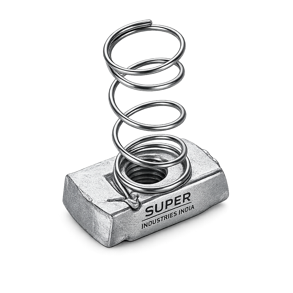
Spring Nuts are integral components within modular support systems widely deployed across industrial, infrastructure, and electromechanical installations. Their functional relevance is closely tied to strut channel-based assembly frameworks, where flexibility, repeatability, and non-welded construction are required.
System-Level Role
Spring Nuts are primarily used in:
- Strut channel systems (41×41, 41×21 profiles)
- Electrical support frameworks
- Cable tray suspension systems
- HVAC duct and pipe support assemblies
- Rail infrastructure mounting systems
- Industrial equipment support structures
These systems rely on modular assembly logic, where components are installed, adjusted, and repositioned without permanent joining processes.
Why Spring Nuts Replace Welded or Tapped Connections
| Parameter | Welded / Tapped Systems | Spring Nut Systems |
|---|---|---|
| Installation | Permanent | Modular |
| Adjustment | Not possible | Fully adjustable |
| On-site modification | Limited | High flexibility |
| Heat-affected zones | Present | Eliminated |
| Reusability | Not feasible | Reusable |
| Installation time | High | Reduced |
Advantages in Modular Systems
- No requirement for pre-threaded holes
- Field adjustability without disassembly
- Elimination of hot work (welding)
- Compatibility with prefabricated channel systems
- Reduction in installation errors
Load Distribution & Repositioning
Spring Nuts distribute load through:
- Bearing on channel lips
- Thread engagement with bolt
- Frictional resistance between nut and channel surface
This enables:
- Controlled load transfer
- Multi-point support configurations
- Dynamic repositioning during installation
2. Technical Definition
Spring Nuts are defined as:
Self-retaining, spring-loaded threaded fasteners designed for insertion into strut channel systems, providing a load-bearing threaded interface without the need for pre-tapping or welding.
Functional Characteristics
- Integrated nut and spring assembly
- Designed for insertion into slotted channel profiles
- Provides positional retention before tightening
- Enables single-hand installation
Types of Spring Nuts
1. Standard Spring Nut
- Integrated spring attached to nut body
- Used for general-purpose channel installations
2. Long Spring Nut
- Extended spring length
- Improved retention in vertical or overhead installations
3. Short Spring Nut
- Compact design
- Suitable for confined channel sections
4. Without Spring (Channel Nuts)
- No retention mechanism
- Requires manual positioning during installation
Channel Compatibility
| Channel Size | Typical Application |
|---|---|
| 41 × 41 mm | Heavy-duty support systems |
| 41 × 21 mm | Medium load installations |
| 41 × 62 mm | High load / double channel |
| Custom profiles | OEM-specific systems |
Compatibility is governed by:
- Channel lip geometry
- Slot width
- Material thickness
Super Industries
Global Manufacturer of Heavy & Custom Engineered Fasteners & Flanges
3. Engineering & Retention Principle
The performance of Spring Nuts is governed by mechanical interaction between:
- Spring force
- Channel geometry
- Threaded interface
- Frictional behavior
Spring Tension Mechanics
The spring provides:
- Initial holding force against channel walls
- Positional stability prior to tightening
- Resistance to displacement during assembly
Spring force is generated through:
- Elastic deformation of hardened spring steel
- Controlled preload during insertion
Channel Lip Engagement
Upon insertion and rotation:
- Nut aligns perpendicular to channel axis
- Edges engage channel lips
- Load is transferred through bearing contact
This creates:
- Mechanical interlock
- Resistance against pull-out
Frictional Locking Behavior
Friction exists between:
- Nut base and channel surface
- Thread interface (bolt-nut)
This contributes to:
- Slip resistance
- Stability under vibration
Thread Load Transfer
Load path:
Bolt → Thread engagement → Nut body → Channel lips → Structure
Critical parameters:
- Thread engagement depth
- Material strength
- Contact surface area
Preload Development During Tightening
Preload is generated when torque is applied:
- Bolt elongates elastically
- Nut resists movement
- Clamping force develops between components
This preload ensures:
- Joint rigidity
- Resistance to loosening
Slip Resistance Theory
Slip occurs when:
Frictional force < Applied shear force
Factors affecting slip:
- Surface finish
- Contact pressure
- Coating type
- Torque level
Vibration Resistance Behavior
Spring Nuts resist vibration through:
- Spring-induced retention force
- Frictional resistance at interfaces
- Preload maintenance
Failure under vibration occurs due to:
- Loss of preload
- Micro-movement
- Thread loosening
4. Load & Mechanical Performance
Spring Nuts are designed to withstand:
1. Static Loads
- Constant load applications
- Equipment mounting
- Cable tray support
2. Dynamic Loads
- HVAC vibration
- Rail-induced movement
- Rotating equipment support
3. Performance Parameters
Pull-Out Resistance
- Resistance against extraction from channel
- Depends on lip engagement and material strength
Slip Load Threshold
- Maximum shear before displacement occurs
Thread Strength
- Governed by material grade and thread depth
4. Failure Modes
| Failure Type | Description |
|---|---|
| Thread stripping | Excessive torque |
| Nut deformation | Overloading |
| Spring fatigue | Cyclic loading |
| Channel lip failure | Overload or poor fit |
| Slip failure | Insufficient preload |
5. Safety Factor Considerations
Engineering practice includes:
- Minimum safety factor: 2.0 – 3.0
- Higher factors for dynamic systems
- Load derating for corrosion environments
6. Load Distribution in Channel
Load is distributed through:
- Bearing at channel lips
- Contact area of nut
- Frictional interface
Improper alignment can result in:
- Uneven load distribution
- Localized stress concentration
Dimensional & Design Logic
Spring Nuts are dimensionally controlled components designed for precise channel fitment.
Thread Sizes
| Metric Size | Typical Use |
|---|---|
| M6 | Light duty |
| M8 | Medium load |
| M10 | General industrial |
| M12 | Heavy-duty |
Key Dimensional Parameters
- Nut width (matching channel slot)
- Nut thickness (load capacity)
- Spring length (retention force)
- Thread depth (engagement strength)
Channel Fit Tolerance
Critical for:
- Proper insertion
- Rotation locking
- Load transfer
Tolerance control ensures:
- No excessive play
- No insertion difficulty
Thread Engagement Depth
Minimum engagement:
- 1 × bolt diameter (standard)
- Increased for softer materials
Tolerance Classes
Threads conform to:
- ISO metric tolerance (6H internal threads)
- Ensures compatibility with standard bolts
Alignment Control
Proper alignment ensures:
- Uniform load transfer
- Reduced stress concentration
- Improved joint life
5. Applicable Standards (ISO / DIN / ASTM)
Spring Nuts are not governed by a single dedicated global standard but are engineered in accordance with multiple interrelated standards covering threads, materials, coatings, and dimensional compatibility with channel systems.
Thread Standards
Spring Nuts utilize ISO metric internal threads compatible with standard fasteners.
| Standard | Description | Relevance |
|---|---|---|
| ISO 261 | Metric thread series | Defines pitch combinations |
| ISO 965 | Thread tolerances | Ensures fit (6H internal threads) |
| DIN 13 | Metric thread profile | Geometry and form |
| DIN 934 | Hex nut dimensions | Reference geometry for threading |
Engineering Implication:
- Ensures compatibility with standard bolts (ISO/DIN compliant)
- Maintains interchangeability across global EPC projects
Nut Geometry Reference Standards
Although Spring Nuts differ from conventional hex nuts, dimensional references are often aligned with:
| Standard | Application |
|---|---|
| DIN 928 | Weld nuts (reference for square geometry) |
| DIN 562 | Square thin nuts |
| DIN 557 | Square nuts |
Purpose:
- Provides baseline geometry for load-bearing thread blocks
- Supports design equivalence for load calculations
Material Standards
Material selection follows ASTM and EN standards.
| Material Type | Applicable Standards |
|---|---|
| Carbon Steel | ASTM A108, ASTM A29 |
| Stainless Steel | ASTM A240, ASTM A276 |
| Spring Steel | EN 10132, ASTM A684 |
Coating & Corrosion Standards
| Standard | Description |
|---|---|
| ASTM B633 | Zinc plating |
| ASTM A153 | Hot-dip galvanizing |
| ISO 4042 | Electroplated coatings |
| ASTM B117 | Salt spray testing |
OEM & Channel Compatibility Standards
Spring Nuts are designed to match:
- Standard strut channel systems (41 mm series)
- OEM channel geometries (Unistrut-type systems)
- Project-specific rail and infrastructure support profiles
Engineering Requirement:
Dimensional compatibility must ensure:
- Correct lip engagement
- Controlled insertion force
- Reliable locking after 90° rotation
6. Material & Grade Options
Material selection directly influences:
- Load-bearing capacity
- Corrosion resistance
- Temperature stability
- Fatigue performance
Carbon Steel Spring Nuts
Used in general industrial environments.
Characteristics:
- Moderate strength
- Economical
- Requires surface protection
Typical Grades:
- Low carbon steel (C15, C20 equivalent)
Stainless Steel Spring Nuts
SS304 (A2)
- Austenitic stainless steel
- Good corrosion resistance
- Suitable for indoor and mild outdoor environments
SS316 (A4)
- Enhanced corrosion resistance
- Resistant to chlorides and marine exposure
- Used in offshore and chemical environments
Spring Material
Spring component is critical to functionality.
Material:
- Hardened spring steel strip
Properties:
- High elastic limit
- Fatigue resistance
- Consistent preload retention
Material Comparison Table
| Grade | Yield Strength (MPa) | Tensile Strength (MPa) | Temperature Range | Corrosion Resistance | Typical Application |
|---|---|---|---|---|---|
| Carbon Steel | 250 – 350 | 400 – 550 | -20°C to 250°C | Low (coating required) | Indoor industrial systems |
| SS304 | 210 – 300 | 500 – 700 | -200°C to 400°C | Moderate | Electrical & HVAC |
| SS316 | 220 – 310 | 500 – 750 | -200°C to 450°C | High | Marine, offshore, chemical |
| Spring Steel | 800 – 1200 | 1000 – 1500 | -40°C to 300°C | Moderate (coated) | Spring element only |
7. Heat Treatment Information
Heat treatment is applied primarily to the spring component and, in some cases, to the nut body depending on strength requirements.
Spring Hardening Process
Steps:
- Austenitizing (heating to critical temperature)
- Quenching (rapid cooling)
- Tempering (controlled reheating)
Quenching & Tempering
Purpose:
- Increase hardness
- Improve elastic recovery
- Enhance fatigue resistance
Stress Relieving
Performed after forming operations to:
- Remove residual stresses
- Prevent distortion
- Improve dimensional stability
Hardness Control
Spring hardness range:
- Typically 40–50 HRC
Control ensures:
- Adequate spring force
- Long fatigue life
- Resistance to permanent deformation
Engineering Impact
| Property | Effect |
|---|---|
| Elasticity | Maintains retention force |
| Fatigue strength | Resists cyclic loading |
| Hardness | Prevents deformation |
| Stress stability | Ensures long-term reliability |
8. Manufacturing Process
Spring Nuts are manufactured through controlled, multi-stage processes ensuring dimensional precision and repeatability.
Raw Material Inspection
- Chemical composition verification
- Mechanical property validation
- Surface defect inspection
Stamping / Pressing
- Sheet metal blanking
- Forming of nut geometry
- Dimensional control via dies
Thread Tapping
- Internal threading using precision taps
- Controlled thread tolerance (ISO 6H)
Spring Forming
- Spring steel strip bending
- Shape forming for preload characteristics
- Heat treatment post-forming
Assembly (Nut + Spring)
- Mechanical attachment of spring to nut body
- Alignment verification
- Retention force calibration
Surface Finishing
- Coating application (as per requirement)
- Corrosion protection treatment
Final Inspection
- Dimensional verification
- Thread gauge testing
- Spring tension validation
Marking & Traceability
- Batch identification
- Material traceability
- Heat number tracking
Dimensional Control Discipline
Critical checkpoints:
- Nut width vs channel slot
- Thread concentricity
- Spring positioning accuracy
- Flatness of contact surfaces
Surface Finish Options
Surface treatment is essential for corrosion protection and service life extension.
Zinc Plating (Electroplated)
- Thickness: 5–25 microns
- Protection mechanism: sacrificial coating
- Suitable for indoor environments
Hot-Dip Galvanizing (HDG)
- Thick zinc layer (50–80 microns)
- Long-term outdoor protection
- Suitable for infrastructure projects
Electro-Galvanized
- Controlled uniform coating
- Improved appearance
- Moderate corrosion resistance
Black Oxide
- Minimal corrosion protection
- Used for indoor or temporary applications
Passivation (Stainless Steel)
- Enhances oxide layer
- Improves corrosion resistance
- No dimensional change
Corrosion Protection Mechanism
| Coating | Mechanism |
|---|---|
| Zinc | Sacrificial protection |
| HDG | Barrier + sacrificial |
| Passivation | Passive oxide film |
| Black oxide | Minimal barrier |
Engineering Considerations for Coating Selection
- Environmental exposure
- Required service life
- Load conditions
- Compatibility with mating components
9. Inspection & Quality Control Methods
Spring Nuts are inspected at multiple stages to ensure compliance with dimensional, mechanical, and coating requirements suitable for EPC and OEM applications.
Thread Gauge Inspection
- GO / NO-GO gauges as per ISO 1502
- Internal thread tolerance: 6H
- Verification of pitch, flank angle, and depth
Dimensional Inspection
Measured parameters:
- Nut width and thickness
- Channel fit dimensions
- Spring length and positioning
- Parallelism and flatness
Tools used:
- Vernier calipers
- Micrometers
- Optical comparators (for profile verification)
Coating Thickness Testing
- Magnetic thickness gauge (for zinc coatings)
- Measurement in microns
- Compliance with ASTM / ISO coating standards
Salt Spray Testing
- Conducted as per ASTM B117
- Evaluates corrosion resistance performance
Typical benchmarks:
| Coating Type | Salt Spray Resistance |
|---|---|
| Zinc plated | 48–96 hours |
| HDG | 250–600 hours |
| SS (passivated) | No red rust |
Hardness Testing
- Rockwell hardness (HRC scale)
- Applied primarily to spring components
Spring Tension Verification
- Load vs deflection testing
- Ensures retention force consistency
- Confirms elastic recovery
Third-Party Inspection (TPI)
Inspection agencies may include:
- Independent inspection bodies
- Client-appointed inspectors
Scope:
- Dimensional validation
- Material verification
- Coating inspection
- Documentation review
Certification
| Certificate | Description |
|---|---|
| EN 10204 3.1 | Manufacturer test certificate |
| EN 10204 3.2 | Third-party verified certification |
ENGINEERING TABLES
A. Technical Dimension Tables (Spring Nuts)
| Thread Size | Channel Compatibility | Nut Width (mm) | Nut Thickness (mm) | Spring Length (mm) |
|---|---|---|---|---|
| M6 | 41 × 21 / 41 × 41 | 18 – 20 | 6 – 8 | 35 – 45 |
| M8 | 41 × 21 / 41 × 41 | 20 – 22 | 7 – 9 | 40 – 50 |
| M10 | 41 × 41 | 22 – 25 | 8 – 10 | 45 – 55 |
| M12 | 41 × 41 / 41 × 62 | 25 – 28 | 10 – 12 | 50 – 65 |
Engineering Note:
Dimensions vary based on OEM channel tolerances and load requirements.
B. Load Capacity Table
| Thread Size | Static Load (kN) | Dynamic Load (kN) | Recommended Safety Factor | Typical Application |
|---|---|---|---|---|
| M6 | 3 – 5 | 2 – 3 | 2.5 | Light supports |
| M8 | 5 – 8 | 3 – 5 | 2.5 | Cable trays |
| M10 | 8 – 12 | 5 – 8 | 3.0 | HVAC systems |
| M12 | 12 – 18 | 8 – 12 | 3.0 | Heavy equipment |
C. Torque Chart
| Thread Size | Property Class | Dry Torque (Nm) | Lubricated Torque (Nm) |
|---|---|---|---|
| M6 | 8.8 | 10 – 12 | 7 – 9 |
| M8 | 8.8 | 25 – 30 | 18 – 22 |
| M10 | 8.8 | 45 – 55 | 32 – 40 |
| M12 | 8.8 | 75 – 90 | 55 – 70 |
Engineering Note:
- Torque values depend on friction coefficient (K factor)
- Over-tightening may cause thread stripping or deformation
- Lubrication reduces required torque but increases preload
D. Preload & Load Calculation Guide
Preload Formula
![\[F = \frac{T}{K \cdot d}\]](https://superindustriesindia.in/wp-content/ql-cache/quicklatex.com-047c3812ff26cb229181955bd579e870_l3.png "Rendered by QuickLaTeX.com")
Where:
- F = Preload force (N)
- T = Applied torque (Nm)
- K = Torque coefficient (typically 0.18 – 0.25)
- d = Nominal diameter (m)
Thread Load Equation
![\[\sigma = \frac{F}{A}\]](https://superindustriesindia.in/wp-content/ql-cache/quicklatex.com-d820ba2a7649df33c4e35cab55485169_l3.png "Rendered by QuickLaTeX.com")
Where:
- σ = Stress (MPa)
- F = Load (N)
- A = Stress area (mm²)
Friction Influence
- Higher friction → Lower preload for same torque
- Lower friction → Higher preload (risk of overloading)
Sample Calculation (M10 Spring Nut)
Given:
- Torque (T) = 50 Nm
- K = 0.2
- Diameter (d) = 0.01 m
Preload:
![\[F = \frac{50}{0.2 \times 0.01} = 25{,}000 \, \text{N}\]](https://superindustriesindia.in/wp-content/ql-cache/quicklatex.com-66963b5f9b80303a4a745a0adfdb825a_l3.png "Rendered by QuickLaTeX.com")
Engineering Interpretation
- Preload must remain below yield strength of nut material
- Excess preload leads to:
- Thread failure
- Channel deformation
E. Mechanical Property Table
| Property | Carbon Steel | SS304 | SS316 | Spring Steel |
|---|---|---|---|---|
| Yield Strength (MPa) | 250 – 350 | 210 – 300 | 220 – 310 | 800 – 1200 |
| Tensile Strength (MPa) | 400 – 550 | 500 – 700 | 500 – 750 | 1000 – 1500 |
| Hardness (HRC) | 15 – 25 | 10 – 20 | 10 – 20 | 40 – 50 |
| Fatigue Life | Moderate | Moderate | High | Very High |
F. Corrosion Resistance Table
| Environment | Carbon Steel (Coated) | SS304 | SS316 |
|---|---|---|---|
| Indoor | Acceptable | Excellent | Excellent |
| Outdoor | Limited | Good | Excellent |
| Industrial | Moderate | Good | Very Good |
| Marine | Not recommended | Limited | Recommended |
10. ENGINEERING INTERPRETATION OF TABLES
Load vs Thread Size Selection
- M6–M8 → Light to medium structural support
- M10–M12 → Load-bearing and vibration-sensitive systems
Torque vs Preload Relationship
- Direct relationship between torque and clamping force
- Must be controlled to avoid:
- Thread stripping
- Spring deformation
- Channel damage
Material Selection Impact
- Carbon steel → cost-effective, requires coating
- SS304 → general corrosion resistance
- SS316 → critical environments
QUALITY ASSURANCE SUMMARY
Spring Nuts supplied for EPC applications must meet:
- Dimensional tolerance compliance
- Thread accuracy (ISO metric)
- Verified mechanical properties
- Coating performance validation
- Traceable documentation
11. Industries Served
Spring Nuts are deployed across multiple sectors where modular support systems, non-welded assemblies, and adjustable structural configurations are required. Their application is defined by compatibility with strut channel systems and the need for repeatable, field-adjustable fastening.
Electrical Infrastructure
Applications include:
- Cable tray suspension systems
- Conduit support frameworks
- Panel board mounting structures
- Substation auxiliary supports
Engineering Requirement:
- Rapid installation without drilling
- Consistent alignment of cable routes
- Compatibility with galvanized channel systems
Railways & Transit Systems
Used in:
- Signaling equipment mounting
- Cable management systems
- Platform infrastructure supports
- Tunnel and elevated corridor installations
Performance Considerations:
- Resistance to vibration and cyclic loads
- Long-term corrosion resistance
- Compatibility with heavy-duty channel systems
HVAC Systems
Applications:
- Duct suspension systems
- Pipe supports
- Equipment mounting (AHUs, chillers)
Engineering Factors:
- Dynamic loading due to airflow and vibration
- Requirement for adjustable positioning
- Load distribution across multiple supports
Oil & Gas Support Systems
Used in:
- Instrumentation support structures
- Secondary steel frameworks
- Cable tray and piping supports
Requirements:
- Corrosion-resistant materials (SS316 / HDG)
- Compliance with project specifications
- Load-bearing capability under environmental exposure
Power Plants
Applications include:
- Electrical raceways
- Auxiliary equipment mounting
- Structural support assemblies
Engineering Considerations:
- High-temperature exposure
- Long service life
- Inspection accessibility
Commercial & Industrial Construction
Used in:
- Structural framing support
- Mechanical system installation
- Modular building systems
Industrial Automation & Equipment Mounting
Applications:
- Machine support structures
- Conveyor systems
- Control panel installations
12. Export Capability & Global Supply
Spring Nuts are supplied for international EPC projects requiring compliance, traceability, and logistics discipline.
Regions Served
- United States
- European Union
- Middle East (UAE, Saudi Arabia, Qatar)
- Southeast Asia
- Africa
Packaging Standards
Packaging is designed to maintain product integrity during transit and storage.
Types:
- Bulk carton packaging
- Palletized shipment
- Moisture-protected wrapping
- Export-grade labeling
Export Documentation
Typical documentation includes:
- Commercial invoice
- Packing list
- Certificate of origin
- Material test certificate (EN 10204 3.1 / 3.2)
- Coating compliance reports
- Inspection reports
Bulk Project Supply Capability
Supply structure supports:
- High-volume EPC requirements
- Batch traceability
- Scheduled dispatches
- Multi-location delivery
Compliance & Traceability
- Heat number traceability
- Batch identification
- Inspection records
- Material certification
13. PROCUREMENT & INSTALLATION VIEW
Installation Methodology for Spring Nuts
Spring Nuts are installed within strut channel systems using a defined sequence to ensure correct engagement and load transfer.
Step 1 – Insertion
- Insert Spring Nut into channel slot
- Align parallel to channel axis
Step 2 – Positioning
- Move nut to required location
- Spring maintains temporary retention
Step 3 – 90-Degree Rotation
- Rotate nut by 90°
- Nut edges engage channel lips
Step 4 – Bolt Insertion
- Insert bolt through fixture/component
- Engage threads with nut
Step 5 – Tightening
- Apply specified torque
- Develop preload
- Lock assembly
Engineering Checks During Installation
- Correct channel compatibility
- Full thread engagement
- Proper torque application
- Alignment with load direction
Reusability Considerations
Spring Nuts can be reused provided:
- Threads are not damaged
- Spring retains elasticity
- No deformation of nut body
Inspection Checkpoints (Field Level)
- Visual inspection for coating damage
- Thread condition verification
- Spring retention performance
- Torque verification
Storage Conditions
- Dry indoor environment
- Protection from moisture exposure
- Segregation by size and grade
- Avoidance of mechanical damage
14. CUSTOM ENGINEERING CAPABILITIES
Spring Nuts can be engineered to meet project-specific requirements beyond standard configurations.
Custom Options Include:
1. Thread Variations
- Metric (M6 to M16 and above)
- UNC / UNF threads (for export projects)
2. Special Spring Designs
- Increased preload springs
- Extended length for vertical installations
- High-fatigue resistance variants
3. High-Load Variants
- Increased nut thickness
- Reinforced geometry
- Higher-grade materials
4. Custom Coatings
- Zinc flake coatings
- PTFE-based coatings
- Project-specific corrosion protection systems
5. Project-Specific Marking
- Batch codes
- Client identification
- Heat number stamping
ENGINEERING SUMMARY FOR PROCUREMENT
When evaluating Spring Nuts for EPC or OEM applications, the following parameters must be verified:
Technical Validation
- Thread standard compliance (ISO metric)
- Load capacity suitability
- Channel compatibility
Material Verification
- Grade confirmation (CS / SS304 / SS316)
- Mechanical property validation
- Corrosion resistance requirement
Manufacturing Quality
- Dimensional accuracy
- Thread integrity
- Spring performance
Coating & Protection
- Coating thickness
- Corrosion resistance test results
Documentation
- EN 10204 certification
- Inspection reports
- Traceability records
CONCLUSION
Spring Nuts function as a critical interface component within modular channel-based support systems, enabling:
- Non-permanent, adjustable fastening
- Load-bearing threaded engagement
- Rapid installation without welding or tapping
Their performance is governed by:
- Thread integrity
- Spring retention force
- Channel compatibility
- Proper torque application
For EPC and industrial applications, correct selection and verification of Spring Nuts must consider:
- Mechanical load requirements
- Environmental conditions
- Material and coating specifications
- Compliance with international standards