
WING NUTS
“Global Manufacturer of Heavy & Custom Engineered Fasteners for Oil & Gas, Power & EPC Contractors.”
1. Industry Context & System Relevance
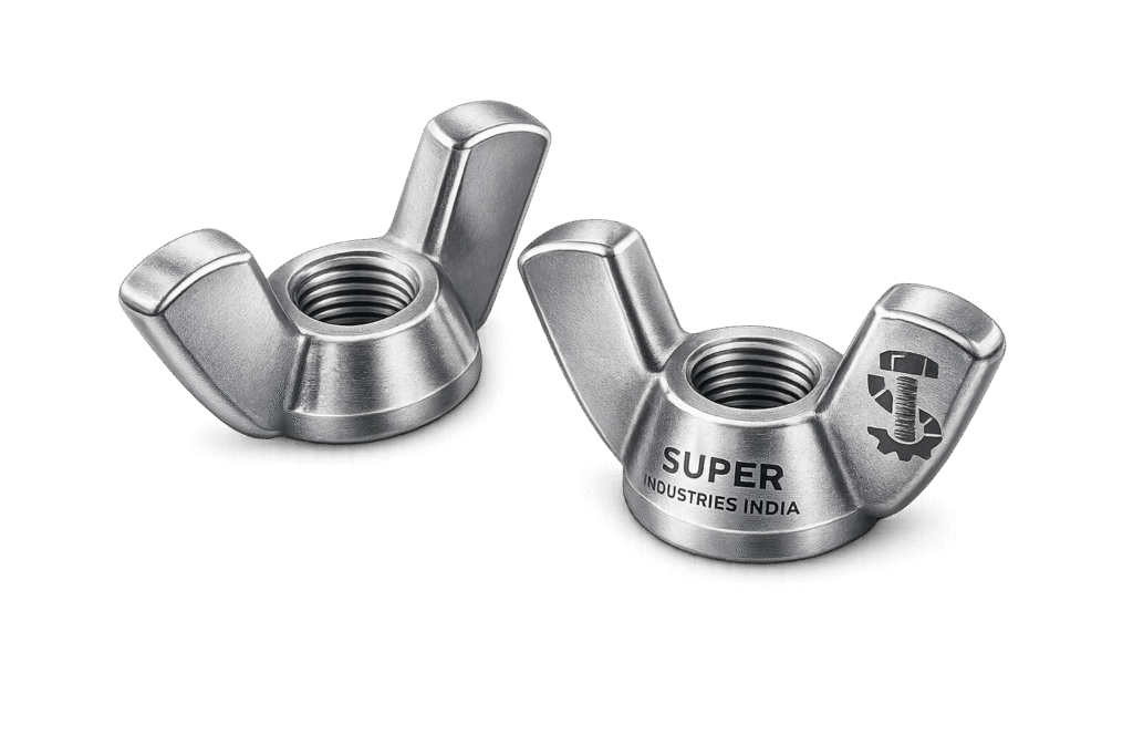
Wing Nuts are specialized threaded fastening elements designed for tool-free tightening and removal, primarily in systems requiring frequent access, adjustment, or temporary assembly. Their functional relevance is not defined by high-load capability, but by operational accessibility and repeatability.
Functional Role in Industrial Systems
Wing Nuts are deployed in applications where:
- Fast assembly/disassembly cycles are required
- Maintenance access is frequent
- Tool availability is restricted or undesirable
- Assembly must be performed under time constraints
Typical System Integration Areas
Oil & Gas Equipment
- Instrumentation panels
- Inspection covers
- Temporary clamps and supports
Power Plants
- Turbine casing access covers
- Electrical enclosure panels
- Control cabinet doors
HVAC Systems
- Duct inspection covers
- Filter housings
- Access panels
Electrical Systems
- Switchgear covers
- Junction box closures
- Cable tray enclosures
Industrial Machinery
- Safety guards
- Belt covers
- Service panels
Infrastructure Installations
- Temporary scaffolding interfaces
- Modular assemblies
- Equipment mounting frames
Selection Logic vs Hex Nuts
Wing Nuts are selected over conventional hex nuts when:
| Criteria | Wing Nuts | Hex Nuts |
|---|---|---|
| Tool Requirement | Not required | Mandatory |
| Assembly Speed | High | Moderate |
| Torque Control | Low | High |
| Load Capacity | Limited | High |
| Repeatability | High | Moderate |
Engineering Interpretation:
Wing Nuts are not substitutes for structural fasteners. They are used where:
- Clamp force requirements are low to moderate
- Precision preload is not critical
- Accessibility outweighs mechanical strength
Limitations in High-Load Applications
Wing Nuts are unsuitable for:
- High-pressure joints
- Structural load-bearing connections
- Critical bolted flange assemblies
- High vibration environments
Reason:
- Limited torque application capability
- Inconsistent preload generation
- Reduced resistance to loosening
2. Technical Definition
Wing Nuts are internally threaded fasteners with extended lateral projections (“wings”), enabling manual torque application without tools.
Core Characteristics
- Hand-tightened threaded fastener
- Dual-wing geometry for grip and torque generation
- Reusable and removable
- Designed for low-to-moderate clamping loads
Standard Classification: DIN 315
The primary governing standard is DIN 315, which defines two types:
Type A (Stamped Steel / Pressed Form)
- Manufactured from sheet metal
- Lightweight construction
- Lower mechanical strength
- Suitable for light-duty applications
Type B (Cast or Forged)
- Heavier construction
- Higher strength
- Better dimensional stability
- Preferred for industrial applications
Pattern Variants
German Pattern
- Wider wings
- Better grip surface
- Higher torque potential
- Preferred in industrial environments
American Pattern
- Narrower wings
- Compact geometry
- Lower torque capability
Manufacturing Variants
| Type | Process | Characteristics |
|---|---|---|
| Cast Wing Nuts | Casting | Economical, moderate strength |
| Forged Wing Nuts | Hot forging | Higher strength, better grain flow |
| Machined Wing Nuts | CNC machining | High precision, limited volume |
Threading Systems
Wing Nuts are available in:
Metric Threads
- ISO metric standard
- Sizes: M4 to M24 (typical industrial range)
Imperial Threads
- UNC (Unified Coarse Thread)
- UNF (Unified Fine Thread)
3. Engineering & Load Principle
Wing Nuts operate on the same threaded fastening mechanics as conventional nuts but are constrained by manual torque application limits.
Manual Torque Generation
Torque is applied through:
- Hand grip force
- Wing geometry leverage
- Surface friction between fingers and nut
Limitation:
Human-applied torque is inherently variable and limited, typically:
- 2 Nm to 25 Nm depending on size and operator
Thread Engagement Mechanics
Load transfer occurs through:
- Contact between internal and external threads
- Frictional resistance along thread flanks
- Bearing surface contact under the nut
Clamping Force Generation
Clamping force (preload) is generated as:
- Torque → rotational motion
- Rotation → axial movement
- Axial movement → compressive force
Torque vs Preload Relationship
The relationship follows standard fastener mechanics:
![\[T = K \cdot F \cdot d\]](https://superindustriesindia.in/wp-content/ql-cache/quicklatex.com-637ae80de10d14a2f4d17cc6dfd9f1fa_l3.png "Rendered by QuickLaTeX.com")
Where:
- (T) = Torque
- (K) = Friction factor
- (F) = Preload
- (d) = Nominal diameter
Engineering Limitation
Unlike torque-controlled tightening:
- Torque cannot be precisely controlled
- Preload varies significantly
- Repeatability is low
Frictional Locking Behavior
Wing Nuts rely on:
- Thread friction
- Bearing surface friction
No inherent locking mechanism exists, unless supplemented by:
- Lock washers
- Spring washers
- Nylon inserts (non-standard modification)
Vibration Considerations
Under vibration:
- Loss of preload is common
- Self-loosening may occur
- Periodic inspection is required
4. Load & Performance Engineering
Load-Bearing Characteristics
Wing Nuts are designed for:
- Light to moderate clamping loads
- Non-structural applications
- Temporary fastening
Static vs Dynamic Applications
| Condition | Suitability |
|---|---|
| Static Loads | Acceptable |
| Dynamic Loads | Limited |
| Impact Loads | Not recommended |
| Vibratory Conditions | Requires additional locking |
Fatigue Considerations
Due to:
- Low preload consistency
- Variable tightening
Wing Nuts are not suitable for fatigue-critical applications.
Recommended Use Cases
- Access panels
- Covers and guards
- Temporary fixtures
- Adjustable assemblies
Unsafe Application Scenarios
Wing Nuts should not be used in:
- Pressure-retaining joints
- Structural steel connections
- Rotating equipment interfaces
- High-temperature bolted joints
Safety Factor Considerations
Due to preload variability:
- Higher safety factors must be assumed
- Conservative load estimation is required
Dimensional & Design Logic
Typical Size Range
| Parameter | Range |
|---|---|
| Thread Size | M4 to M24 |
| Thread Pitch | ISO standard |
| Nut Height | Proportional to diameter |
| Wing Span | Size-dependent |
Key Design Elements
Wing Geometry
- Determines torque capability
- Influences ergonomic grip
Nut Height
- Controls thread engagement
- Affects load distribution
Thread Depth
- Critical for load transfer
- Must meet ISO thread standards
Tolerance & Standards
Threads conform to:
- ISO metric tolerance classes (e.g., 6H)
- UNC/UNF tolerances for imperial variants
Ergonomics vs Strength Trade-off
| Factor | Impact |
|---|---|
| Larger wings | Better torque, higher stress |
| Smaller wings | Lower torque, improved compactness |
Manufacturing Influence on Dimensions
Casting
- Wider tolerances
- Surface irregularities
Forging
- Improved grain structure
- Better dimensional consistency
Machining
- Highest precision
- Tight tolerances
Surface Finish Expectations
- Casting: Rough surface
- Forged: Moderate finish
- Machined: Smooth finish
Engineering Observation
Wing Nut design is a compromise between:
- Human operability
- Mechanical integrity
5. Applicable Standards (ASTM / DIN / ISO / ASME)
Wing Nuts are governed by a combination of dimensional standards, threading standards, and material specifications. Unlike structural fasteners, their compliance focus is geometry, fitment, and material integrity, rather than high-load certification.
Primary Dimensional Standard
DIN 315 — Wing Nuts
DIN 315 defines:
- Overall geometry
- Wing configuration
- Dimensional proportions
- Type classification (Type A / Type B)
Engineering Relevance:
| Parameter | Impact |
|---|---|
| Wing Span | Determines torque capability |
| Nut Height | Defines thread engagement |
| Internal Thread | Governs load transfer |
Thread Standards
ISO Metric Threads
- ISO 261 — General plan
- ISO 965 — Tolerances (e.g., 6H internal threads)
Application:
- Global EPC projects
- European and Asian markets
Unified Thread Standards (UNC/UNF)
- ASME B1.1 — Unified thread system
Application:
- North American projects
- Oil & Gas installations using imperial systems
ASME Fastener Standards
While Wing Nuts are not explicitly covered under heavy structural categories:
- ASME B18 series provides general guidance for:
- Thread quality
- Fitment
- Dimensional practices
ASTM Material Standards
Material selection is governed by:
| Standard | Application |
|---|---|
| ASTM A105 | Carbon steel (machined variants) |
| ASTM A182 F304 / F316 | Stainless steel Wing Nuts |
| ASTM B16 | Brass materials |
Standards Mapping to Application Conditions
| Condition | Applicable Standard |
|---|---|
| General Industrial Use | DIN 315 + ISO Threads |
| Corrosive Environments | ASTM A182 (SS) |
| Oil & Gas Projects | ASTM + ASME + ISO |
| Export (US Market) | UNC/UNF + ASME B1.1 |
Engineering Note
Wing Nuts are typically dimensionally standardized but mechanically application-dependent, meaning:
- Standards ensure interchangeability
- Engineering judgment governs suitability
6. Material & Grade Options
Material selection defines:
- Corrosion resistance
- Mechanical strength
- Temperature capability
- Service life
A. Carbon Steel Wing Nuts
Typical Grades
- Low Carbon Steel (C15, C20 equivalent)
- ASTM A105 (for machined components where applicable)
Characteristics
- Moderate strength
- Economical
- Suitable for indoor or controlled environments
Limitations
- Prone to corrosion without coating
- Limited performance in aggressive environments
B. Stainless Steel Wing Nuts
ASTM A182 F304
- General-purpose corrosion resistance
- Suitable for atmospheric and mild chemical exposure
ASTM A182 F316
- Enhanced corrosion resistance
- Suitable for:
- Marine environments
- Chloride exposure
- Offshore applications
Engineering Properties
| Property | F304 | F316 |
|---|---|---|
| Corrosion Resistance | Good | Superior |
| Chloride Resistance | Moderate | High |
| Temperature Resistance | Moderate | High |
C. Non-Ferrous Materials
Brass Wing Nuts
- Non-sparking
- Good corrosion resistance
- Used in electrical and low-load environments
Aluminum Wing Nuts
- Lightweight
- Moderate corrosion resistance
- Low mechanical strength
D. Coated & Specialty Variants
- Zinc-coated carbon steel
- Hot-dip galvanized variants
- Polymer-coated Wing Nuts
Used where:
- Corrosion resistance is required without stainless steel cost
Material Comparison Table
| Material Grade | Yield Strength (MPa) | Tensile Strength (MPa) | Temperature Range | Corrosion Resistance | Typical Use |
|---|---|---|---|---|---|
| Low Carbon Steel | ~250 | 400–550 | -20°C to 300°C | Low (requires coating) | General industrial |
| ASTM A105 | ~250 | 485–620 | -29°C to 425°C | Low | Machined applications |
| ASTM A182 F304 | ~205 | 515–720 | -196°C to 870°C | Good | Chemical, HVAC |
| ASTM A182 F316 | ~205 | 515–750 | -196°C to 870°C | Excellent | Marine, offshore |
| Brass | ~200 | 300–500 | -100°C to 200°C | Good | Electrical |
| Aluminum | ~150 | 250–350 | -50°C to 150°C | Moderate | Lightweight assemblies |
Engineering Interpretation
Material selection must consider:
- Environment > Load (primary factor for Wing Nuts)
- Strength is secondary due to torque limitations
- Corrosion resistance directly affects usability and life cycle
7. Heat Treatment Information
Wing Nuts are not always heat treated, but for certain applications, heat treatment improves:
- Thread durability
- Wear resistance
- Mechanical stability
Heat Treatment Processes
1. Normalizing
- Refines grain structure
- Improves uniformity
Application:
- Carbon steel forged Wing Nuts
2. Case Hardening (Selective Use)
- Hard outer surface
- Tough inner core
Benefit:
- Improved thread wear resistance
3. Stress Relieving
- Removes residual stresses
- Prevents distortion
Hardness Ranges
| Material | Typical Hardness |
|---|---|
| Carbon Steel | 120–180 HB |
| Heat Treated Steel | Up to 220 HB |
| Stainless Steel | 150–200 HB |
Engineering Impact
- Excessive hardness → brittle wings (risk of fracture)
- Insufficient hardness → thread wear
Balance is required between:
- Ductility (wing flexibility)
- Thread durability
Manufacturing Process
Wing Nuts are produced through controlled industrial processes, ensuring dimensional compliance and thread integrity.
Step-by-Step Manufacturing Workflow
1. Raw Material Inspection
- Chemical composition verification
- Visual and dimensional inspection
- Traceability marking
2. Forming Process
Casting (Type B / Economical Production)
- Molten metal poured into molds
- Suitable for large volumes
Hot Forging (Preferred for Industrial Use)
- Improves grain flow
- Enhances mechanical strength
Sheet Metal Stamping (Type A)
- Used for lightweight Wing Nuts
- Lower strength category
3. CNC Threading
- Internal threads machined or tapped
- Ensures compliance with:
- ISO metric
- UNC/UNF
4. Wing Shaping
- Precision forming of wings
- Controlled geometry for ergonomic grip
5. Surface Finishing
- Removal of burrs
- Surface smoothing
6. Heat Treatment (If Required)
- Applied based on material and application
7. Surface Coating
- Zinc plating / galvanizing / passivation
8. Final Inspection
- Dimensional verification
- Thread gauge testing
9. Marking & Traceability
- Batch identification
- Heat number traceability (where applicable)
Engineering Observation
Manufacturing accuracy directly affects:
- Thread engagement quality
- Torque transmission efficiency
- Service reliability
8. Surface Finish Options
Surface finish is critical for:
- Corrosion protection
- Friction control
- Service life
Common Surface Finishes
Zinc Plating
- Electroplated coating
- Moderate corrosion resistance
Hot-Dip Galvanizing (HDG)
- Thick zinc layer
- Suitable for outdoor environments
Black Oxide
- Minimal corrosion protection
- Used in indoor applications
Nickel Plating
- Improved corrosion resistance
- Better surface finish
Stainless Steel Passivation
- Removes free iron
- Enhances corrosion resistance
Surface Finish vs Performance
| Finish | Corrosion Resistance | Friction Impact | Application |
|---|---|---|---|
| Zinc Plating | Moderate | Low friction | General use |
| HDG | High | Higher friction | Outdoor |
| Black Oxide | Low | Moderate | Indoor |
| Nickel | Moderate-High | Smooth | Precision |
| Passivation | High (SS only) | Neutral | Corrosive environments |
Engineering Note
Surface finish affects:
- Torque-to-preload relationship
- Thread friction coefficient
- Long-term usability
9. Dimensional Engineering Tables
Dimensional control for Wing Nuts is governed by DIN 315 geometry combined with ISO / UNC thread systems. The following table provides typical industrial reference dimensions (values may vary by manufacturer tolerances and pattern type).
A. Dimensional Table (Reference – DIN 315 Type B Preferred)
| Thread Size | Thread Pitch (mm) | Wing Span (mm) | Nut Height (mm) | Thread Depth (mm) |
|---|---|---|---|---|
| M4 | 0.7 | 18–22 | 8–10 | 4–5 |
| M5 | 0.8 | 20–25 | 10–12 | 5–6 |
| M6 | 1.0 | 25–30 | 12–14 | 6–8 |
| M8 | 1.25 | 30–40 | 14–18 | 8–10 |
| M10 | 1.5 | 40–50 | 18–22 | 10–12 |
| M12 | 1.75 | 50–65 | 22–26 | 12–15 |
| M16 | 2.0 | 65–80 | 26–32 | 15–18 |
| M20 | 2.5 | 80–100 | 32–40 | 18–22 |
| M24 | 3.0 | 100–120 | 40–50 | 22–26 |
Engineering Interpretation
- Wing Span ↑ → Torque Capability ↑
- Thread Depth ↑ → Load Distribution ↑
- Nut Height ↑ → Engagement Reliability ↑
However:
- Larger wings introduce bending stress concentration
- Excessive height increases material usage without proportional benefit
Load Guidance Table
Wing Nuts are not designed for standardized structural loads. The following table provides indicative safe application ranges, assuming:
- Manual tightening only
- Standard friction conditions
- No dynamic loading
B. Load Guidance Table
| Thread Size | Recommended Load Range (kN) | Application Type |
|---|---|---|
| M4 | 0.5 – 1.0 | Light covers, electrical panels |
| M5 | 0.8 – 1.5 | Instrument enclosures |
| M6 | 1.0 – 2.5 | HVAC panels |
| M8 | 2.0 – 4.0 | Machine guards |
| M10 | 3.0 – 6.0 | Access covers |
| M12 | 5.0 – 8.0 | Structural light-duty fixtures |
| M16 | 8.0 – 12.0 | Heavy panels (manual only) |
| M20 | 10.0 – 18.0 | Temporary assemblies |
| M24 | 15.0 – 25.0 | Non-critical large fixtures |
Engineering Limitations
These values assume:
- Static loading
- Proper thread engagement
- Use of washers where applicable
Not valid for:
- Pressure joints
- High-temperature service
- Fatigue loading
Torque Reference Guide
Torque applied to Wing Nuts is limited by human grip capability and wing geometry.
C. Approximate Hand Torque Values
| Thread Size | Typical Hand Torque (Nm) | Max Achievable Preload (kN) |
|---|---|---|
| M4 | 1 – 2 | ~0.5 |
| M5 | 2 – 3 | ~0.8 |
| M6 | 3 – 5 | ~1.2 |
| M8 | 5 – 10 | ~2.5 |
| M10 | 8 – 15 | ~4.0 |
| M12 | 10 – 20 | ~6.0 |
| M16 | 15 – 25 | ~10.0 |
| M20 | 20 – 30 | ~15.0 |
| M24 | 25 – 40 | ~20.0 |
Engineering Observations
- Torque variation between operators can exceed ±40%
- Surface finish significantly affects achievable preload
- Lubrication increases preload for same torque
Preload Calculation Guide
Wing Nuts follow standard fastener preload relationships, but with limited control accuracy.
D. Torque–Preload Relationship
Where:
- (T) = Applied torque (Nm)
- (K) = Friction factor (0.15–0.25 typical)
- (F) = Preload (N)
- (d) = Nominal diameter (m)
Sample Calculation (M10 Wing Nut)
Assume:
- Torque (T = 12 , Nm)
- Diameter (d = 0.01 , m)
- Friction factor (K = 0.2)
![\[F = \frac{T}{K \cdot d} = \frac{12}{0.2 \cdot 0.01} = 6000 \, \text{N}\]](https://superindustriesindia.in/wp-content/ql-cache/quicklatex.com-fdde77811ccfceb1b90d60a9e7836cfa_l3.png "Rendered by QuickLaTeX.com")
Result:
- Preload ≈ 6 kN
Practical Limitation
- Friction factor variability leads to ±30–50% preload uncertainty
- Not suitable for precision clamping applications
Engineering Conclusion
Wing Nuts provide:
- Approximate preload only
- Not controlled tightening
- Not repeatable preload across installations
Mechanical Property Table
Mechanical properties depend on material selection and processing.
E. Mechanical Properties Table
| Material | Yield Strength (MPa) | Tensile Strength (MPa) | Hardness |
|---|---|---|---|
| Carbon Steel | ~250 | 400–550 | 120–180 HB |
| ASTM A105 | ~250 | 485–620 | 130–190 HB |
| SS304 | ~205 | 515–720 | 150–200 HB |
| SS316 | ~205 | 515–750 | 150–200 HB |
| Brass | ~200 | 300–500 | 80–150 HB |
Engineering Interpretation
- Strength exceeds usable preload in most cases
- Failure is more likely due to:
- Thread stripping
- Wing deformation
- Improper application
Corrosion Resistance Table
Material selection must align with environmental exposure.
F. Corrosion Resistance Comparison
| Material | Atmospheric | Marine | Chemical | Outdoor |
|---|---|---|---|---|
| Carbon Steel | Low | Very Low | Poor | Low |
| SS304 | Good | Moderate | Moderate | Good |
| SS316 | Excellent | Excellent | High | Excellent |
| Brass | Good | Moderate | Moderate | Good |
Engineering Conclusion
- SS316 preferred for offshore
- SS304 for general industrial use
- Carbon steel only with protective coating
10. Inspection & Quality Control
Wing Nuts require dimensional, material, and surface verification, even though they are non-critical fasteners.
A. Thread Inspection
- Go/No-Go gauges
- Compliance with:
- ISO 965 (metric)
- ASME B1.1 (UNC/UNF)
B. Dimensional Inspection
- Wing span measurement
- Nut height verification
- Thread depth confirmation
C. PMI Testing (Positive Material Identification)
Applicable for:
- Stainless steel
- Alloy materials
Ensures:
- Correct material grade
- Compliance with ASTM standards
D. Hardness Testing
- Brinell hardness test (HB)
- Confirms heat treatment consistency
E. Coating Thickness Testing
- Zinc plating thickness (microns)
- Galvanization thickness verification
F. Visual Inspection
- Surface defects
- Casting irregularities
- Thread damage
Certification & Documentation
Wing Nuts supplied for EPC projects may require:
EN 10204 Certification
| Type | Description |
|---|---|
| 2.1 | Declaration of compliance |
| 2.2 | Test report |
| 3.1 | Mill test certificate |
| 3.2 | Third-party verified certificate |
Third-Party Inspection
Conducted by:
- Independent inspection agencies
- Client-appointed inspectors
Documentation Includes
- Material test certificates
- Dimensional inspection reports
- Coating reports
- Heat treatment records (if applicable)
Traceability
Maintained through:
- Batch numbers
- Heat numbers
- Manufacturing records
Engineering Note
Traceability is critical for:
- Project compliance
- Failure investigation
- Lifecycle tracking
11. Industries Served
Wing Nuts are deployed across multiple industries where tool-free fastening, accessibility, and repeatability are required. Their selection is governed by operational convenience rather than structural load capacity.
Oil & Gas Industry
Application Areas:
- Instrumentation panel covers
- Inspection ports
- Temporary supports and brackets
Engineering Considerations:
- Preference for stainless steel (ASTM A182 F316) in offshore environments
- Use limited to non-pressure retaining components
- Regular inspection due to vibration exposure
Power Generation
Application Areas:
- Turbine enclosure access panels
- Control cabinet covers
- Auxiliary system housings
Engineering Considerations:
- Temperature exposure requires material compatibility
- Typically used in secondary fastening roles
Electrical & Control Systems
Application Areas:
- Junction boxes
- Switchgear panels
- Cable tray covers
Engineering Considerations:
- Frequent maintenance access
- Non-sparking materials (brass) in specific environments
HVAC Systems
Application Areas:
- Duct inspection covers
- Filter access panels
- Ventilation housing assemblies
Engineering Considerations:
- Corrosion resistance in humid environments
- Moderate clamping loads
Infrastructure & Construction
Application Areas:
- Temporary assemblies
- Modular structural interfaces
- Equipment mounting supports
Engineering Considerations:
- Ease of installation and removal
- Suitability for repetitive use
Industrial Equipment Manufacturing
Application Areas:
- Machine guards
- Safety covers
- Maintenance access panels
Engineering Considerations:
- Compliance with safety access requirements
- Quick removal during servicing
12. Export Capability & Global Supply
Super Industries operates as a manufacturer and exporter of Wing Nuts, supplying to EPC contractors and industrial clients across multiple regions.
Export Regions
- North America (USA, Canada)
- European Union
- Middle East (UAE, Saudi Arabia, Qatar)
- Southeast Asia
Compliance with International Requirements
Products are manufactured in alignment with:
- DIN / ISO dimensional standards
- ASTM material specifications
- ASME thread standards
Packaging Standards
Industrial packaging is executed to ensure:
- Protection against corrosion
- Prevention of thread damage
- Ease of identification and traceability
Typical Packaging Formats:
- Bulk packaging (HDPE-lined boxes)
- Palletized shipments
- Moisture-controlled packaging (VCI)
Export Documentation
Standard export documentation includes:
- Commercial Invoice
- Packing List
- Certificate of Origin
- EN 10204 3.1 / 3.2 certificates
- Third-party inspection reports (if required)
Logistics & Project Supply
- Consolidated shipments for EPC projects
- Batch traceability maintained across shipments
- Capability for scheduled dispatches aligned with project timelines
Engineering Observation
Export readiness is defined by:
- Documentation accuracy
- Dimensional consistency
- Material traceability
Procurement & Installation Practices
Wing Nuts must be specified and installed with an understanding of their mechanical limitations and intended function.
A. Procurement Guidelines
Specification Requirements
Procurement documentation should clearly define:
- Thread size and pitch (Metric / UNC / UNF)
- Material grade (e.g., SS304, SS316, carbon steel)
- Surface finish (zinc plated, HDG, passivated)
- Applicable standard (DIN 315 Type A or B)
Inspection Requirements
- Dimensional inspection compliance
- Thread gauge verification
- Material certification review
Engineering Selection Criteria
| Parameter | Requirement |
|---|---|
| Load Condition | Low to moderate |
| Environment | Corrosion-based selection |
| Accessibility | High priority |
| Reusability | Required |
B. Installation Best Practices
Hand Tightening
- Apply torque using uniform manual force
- Avoid use of tools (unless specifically designed for reinforced Wing Nuts)
Use of Washers
Washers are recommended to:
- Distribute load
- Protect mating surfaces
- Reduce localized stress
Avoiding Over-Tightening
Over-tightening can result in:
- Wing deformation
- Thread stripping
- Reduced service life
Alignment Control
Ensure:
- Proper thread alignment before tightening
- No cross-threading
C. Operational Maintenance
Inspection Frequency
- Periodic inspection required in vibrating systems
- Check for:
- Loosening
- Corrosion
- Thread wear
Replacement Criteria
Replace Wing Nuts if:
- Threads are worn or damaged
- Wings are bent or cracked
- Corrosion affects functionality
Reusability Consideration
Wing Nuts are reusable, but:
- Performance degrades with wear
- Thread condition must be verified before reuse
13. Custom Engineering Capabilities
Super Industries provides customization aligned with project-specific EPC requirements.
Custom Thread Configurations
- Non-standard metric sizes
- UNC / UNF variations
- Fine pitch threads
Custom Wing Geometry
- Extended wings for higher torque
- Reinforced wing sections
- Compact designs for space-constrained applications
Material Customization
- High-grade stainless steels
- Special alloys (on request)
- Non-magnetic or non-sparking materials
Surface Coating Customization
- PTFE coatings
- Heavy galvanization
- Multi-layer corrosion protection systems
Marking & Traceability
- Batch marking
- Heat number stamping
- Client-specific identification
Engineering Capability Note
Customization is limited by:
- Manual torque constraints
- Application safety considerations
Engineering Limitations & Risk Awareness
Wing Nuts must be evaluated with clear understanding of limitations:
Primary Constraints
- Limited torque application
- Uncontrolled preload
- Low resistance to vibration
Failure Modes
- Thread stripping
- Wing deformation
- Loosening under cyclic loading
Mitigation Measures
- Use of locking washers
- Periodic inspection
- Conservative load design
Engineering Conclusion
Wing Nuts are specialized fastening components designed for:
- Accessibility
- Speed of operation
- Repeatable manual assembly
They are not intended for:
- Structural load-bearing
- Pressure containment
- High-vibration or fatigue-critical applications
Final Engineering Position
For EPC and industrial applications:
- Wing Nuts serve as auxiliary fastening elements
- Selection must prioritize:
- Environment
- Accessibility
- Load limitation
Technical Validation Statement
A correctly specified and applied Wing Nut demonstrates:
- Compliance with dimensional standards (DIN 315)
- Appropriate material selection (ASTM / ISO)
- Adequate performance within defined load limits