
DISTORTED THREAD NUTS
Super Industries
“Global Manufacturer of Heavy & Custom Engineered Fasteners for Oil & Gas, Power & EPC Contractors.”
1. Industry Context & System Relevance
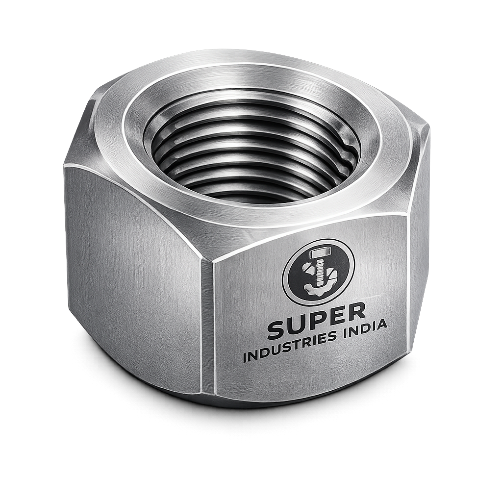
Distorted Thread Nuts are deployed in fastening systems where vibration resistance, clamp load retention, and long-term mechanical integrity are mandatory design requirements. These nuts are classified as all-metal prevailing torque fasteners, designed to maintain joint integrity under dynamic service conditions.
Functional Role in Engineering Systems
These nuts are used across multiple engineering environments:
High-Vibration Mechanical Assemblies
- Rotating equipment (compressors, turbines, pumps)
- Gearbox housings
- Engine assemblies
- Subjected to cyclic loading and transverse vibration
Structural Steel Connections
- Bridges and transmission towers
- Pre-engineered buildings (PEB structures)
- Crane structures and gantries
Pressure Systems
- Flanged joints in piping systems
- Valve assemblies
- Heat exchangers
- Boiler and pressure vessel connections
Oil & Gas Installations
- Offshore platforms
- Refinery piping systems
- Drilling rigs
- Subsea equipment
Power Plants
- Steam turbine assemblies
- Structural supports
- High-temperature bolted joints
Automotive & Heavy Machinery
- Suspension systems
- Axle assemblies
- Construction equipment
Requirement for Self-Locking Fasteners
Standard hex nuts rely purely on:
- Thread friction
- Clamp load
Under dynamic conditions, this becomes insufficient due to:
Loss of Preload
- Embedment relaxation
- Material creep
- Surface flattening
Vibration-Induced Loosening
- Micro-slippage between contact surfaces
- Relative transverse motion
Thermal Expansion Effects
- Differential expansion between bolt and joint materials
- Resulting in preload variation
Failure Modes of Conventional Nuts
| Failure Mode | Description | Impact |
|---|---|---|
| Self-loosening | Rotation under vibration | Joint separation |
| Fatigue failure | Loss of preload leading to cyclic stress | Bolt fracture |
| Embedment relaxation | Surface roughness compression | Clamp force reduction |
| Thermal cycling loosening | Expansion/contraction cycles | Progressive loosening |
Comparison with Other Locking Systems
| Locking Method | Mechanism | Limitations |
|---|---|---|
| Nylon Insert Nuts | Polymer friction ring | Temperature limitation (~120°C) |
| Double Nutting | Jam nut creates opposing force | Installation complexity |
| Chemical Locking (Threadlocker) | Adhesive bonding | Cure time, disassembly difficulty |
| Lock Washers | Spring force | Limited vibration resistance |
| Distorted Thread Nuts | Metal thread interference | No temperature limitation, reusable |
Distorted Thread Nuts eliminate reliance on polymers and adhesives, making them suitable for high-temperature and critical mechanical applications.
Super Industries
Global Manufacturer of Heavy & Custom Engineered Fasteners & Flanges
2. Technical Definition
Distorted Thread Nuts are defined as:
All-metal prevailing torque nuts incorporating controlled thread deformation to generate frictional resistance against bolt threads, preventing self-loosening under dynamic loading conditions.
Core Characteristics
- All-metal construction
- No polymer inserts
- Controlled thread distortion
- Reusable within defined limits
- Temperature-stable
- Compatible with standard bolts
Types of Distorted Thread Nuts
Top Lock Distorted Thread Nuts
- Deformation applied at top threads
- Most common configuration
- Maintains load-bearing threads intact
Elliptical Offset Nuts
- Oval-shaped thread deformation
- Produces uniform interference
Triangular Distorted Nuts
- Three-point deformation
- Balanced locking force
Segmental Deformation Designs
- Localized thread distortion
- Controlled torque characteristics
Prevailing Torque Concept
Prevailing torque is defined as:
The torque required to rotate the nut on a bolt without axial clamp load engagement.
This torque is generated due to:
- Thread interference
- Elastic/plastic deformation
- Increased frictional resistance
3. Engineering & Locking Principle
Thread Interference Mechanism
Distorted Thread Nuts function by introducing intentional geometric interference between:
- Internal nut threads
- External bolt threads
This interference generates:
- Radial pressure
- Frictional resistance
- Mechanical locking
Elastic vs Plastic Deformation
| Zone | Behavior | Function |
|---|---|---|
| Elastic | Recoverable deformation | Maintains repeated locking capability |
| Plastic | Permanent deformation | Ensures initial locking force |
The design balances:
- Sufficient plastic deformation for locking
- Controlled elastic recovery for reusability
Frictional Resistance Generation
The locking torque is produced by:
- Increased normal force between threads
- Higher friction coefficient
- Contact pressure distribution
Prevailing Torque vs Installation Torque
| Torque Type | Description |
|---|---|
| Prevailing Torque | Resistance before seating |
| Installation Torque | Total torque including clamp load |
Total Torque = Prevailing Torque + Clamp Load Torque
Clamp Load Retention
Clamp load is maintained due to:
- Resistance to rotational loosening
- Continuous thread friction
- Stability under vibration
Torque–Tension Relationship (Conceptual)
The torque applied to a fastener is related to clamp load by:
- Friction under threads
- Bearing surface friction
- Thread pitch
This relationship is influenced by:
- Lubrication
- Surface finish
- Coating
(Detailed calculation provided in Part 3)
Effect of Lubrication
| Condition | Effect |
|---|---|
| Dry | Higher friction, higher torque required |
| Lubricated | Reduced torque, higher clamp load efficiency |
Lubrication directly impacts:
- Installation torque
- Prevailing torque values
Reusability Limits
Distorted Thread Nuts are reusable, subject to:
- Retention of prevailing torque
- No thread damage
- Compliance with torque specifications
Repeated use results in:
- Gradual reduction in prevailing torque
Temperature Stability
Unlike nylon insert nuts:
| Property | Distorted Thread Nuts | Nylon Insert Nuts |
|---|---|---|
| Temperature Range | Up to 500°C+ (material dependent) | ~120°C max |
| Creep Resistance | High | Low |
| Chemical Resistance | High | Limited |
4. Load & Vibration Engineering
Dynamic Load Resistance
Distorted Thread Nuts maintain joint integrity under:
- Axial loads
- Shear loads
- Combined loading conditions
Vibration Loosening (Junker Effect)
The Junker test demonstrates:
- Standard nuts loosen rapidly under transverse vibration
- Prevailing torque nuts resist rotational movement
Mechanism:
- Transverse displacement causes micro-rotation
- Distorted threads counteract this rotation
Transverse Movement Resistance
The locking mechanism:
- Maintains frictional resistance
- Prevents slip between threads
- Stabilizes joint under lateral motion
Fatigue Performance
Maintained preload reduces:
- Stress fluctuation in bolts
- Fatigue crack initiation
Clamp Force Decay
Clamp force loss occurs due to:
- Embedment
- Material relaxation
Distorted Thread Nuts:
- Slow down clamp force decay
- Maintain preload longer than standard nuts
Prevailing Torque Retention After Cycles
- Initial installation → highest torque
- Subsequent cycles → gradual reduction
- Acceptable limits defined by ISO 2320
Performance Under Thermal Cycling
Under temperature variation:
- Metal structure remains stable
- No degradation as in polymer inserts
- Maintains locking efficiency
5. Applicable Standards (ISO / DIN / ASTM / ASME)
Distorted Thread Nuts are governed by a combination of dimensional, mechanical, and performance validation standards. Compliance with these standards ensures suitability for EPC-grade applications, particularly in safety-critical assemblies.
ISO Standards
ISO 7042 – Prevailing Torque Type All-Metal Hexagon Nuts
- Defines geometry for all-metal prevailing torque nuts (top lock type)
- Specifies:
- Nut dimensions
- Thread engagement
- Mechanical requirements
- Applicable to:
- Metric thread systems
- General industrial and structural applications
ISO 2320 – Prevailing Torque Testing
- Governs:
- Measurement of prevailing torque
- First installation torque
- Reuse torque values
- Defines:
- Minimum and maximum torque limits
- Test methodology (with/without lubrication)
- Mandatory for:
- Performance validation
- Batch acceptance
DIN Standards
DIN 980 – All-Metal Self-Locking Nuts
- Covers:
- Top lock and deformed thread designs
- Specifies:
- Dimensional tolerances
- Locking characteristics
DIN 982 – Prevailing Torque Nuts (High Type)
- Defines:
- Increased nut height
- Enhanced thread engagement
- Used in:
- High-load structural applications
ASTM Standards
ASTM A194 – Carbon & Alloy Steel Nuts for Pressure Systems
- Applicable for:
- High-pressure and high-temperature applications
- Grades include:
- 2H, 7, 7M
- Used in:
- Oil & gas
- Refineries
- Boilers
ASTM A563 – Carbon Steel Nuts
- Covers:
- Structural and general-purpose nuts
- Grade DH commonly used for:
- Heavy structural connections
ASME Standards
ASME B18.2.2 – Dimensional Standard for Nuts
- Defines:
- Across flats
- Nut height
- Thread compatibility (UNC/UNF)
- Applicable in:
- US-based EPC projects
Standards Mapping to Engineering Conditions
| Standard | Focus Area | Application Condition |
|---|---|---|
| ISO 7042 | Geometry & design | General industrial fastening |
| ISO 2320 | Performance testing | Torque validation & QA |
| DIN 980 / 982 | Locking geometry | Structural & mechanical systems |
| ASTM A194 | High temp/pressure | Oil & gas, power |
| ASTM A563 | Structural grade | Steel structures |
| ASME B18.2.2 | Dimensional compatibility | North American systems |
6. Material & Grade Options
Material selection for Distorted Thread Nuts is based on:
- Load requirements
- Temperature exposure
- Corrosion environment
- Compatibility with mating bolts
Carbon Steel Grades
ASTM A563 Grade DH
- High-strength structural applications
- Used with:
- A325 / A490 bolts
ASTM A194 Grade 2H
- Quenched and tempered carbon steel
- Suitable for:
- Pressure vessel applications
Stainless Steel Grades
A2-70
- Equivalent to 304 stainless steel
- Moderate corrosion resistance
A4-80
- Equivalent to 316 stainless steel
- Enhanced corrosion resistance (marine, chemical)
Alloy Steel Grades
ASTM A194 Grade 7 / 7M
- Designed for:
- High-temperature service
- 7M variant provides:
- Improved toughness at low temperatures
Special Materials
Duplex / Super Duplex Stainless Steel
- High strength + corrosion resistance
- Used in:
- Offshore and subsea systems
Nickel Alloys (e.g., Inconel-type)
- High temperature resistance
- Oxidation resistance
- Used in:
- Extreme environments
Material Comparison Table
| Material Grade | Yield Strength (MPa) | Tensile Strength (MPa) | Temperature Range | Corrosion Resistance | Typical Use |
|---|---|---|---|---|---|
| ASTM A563 DH | ~450 | ~620 | -20°C to 300°C | Low | Structural steel |
| ASTM A194 2H | ~515 | ~690 | -29°C to 425°C | Low | Pressure systems |
| A2-70 | ~450 | ~700 | -50°C to 300°C | Moderate | General industrial |
| A4-80 | ~600 | ~800 | -50°C to 400°C | High | Marine, chemical |
| A194 Gr 7 | ~720 | ~860 | -29°C to 450°C | Moderate | High-temp systems |
| Duplex SS | ~450–550 | ~700–800 | -50°C to 300°C | Very High | Offshore |
| Nickel Alloy | >600 | >900 | Up to 700°C+ | Excellent | Extreme environments |
7. Heat Treatment Information
Heat treatment is critical for:
- Achieving mechanical properties
- Maintaining thread integrity
- Ensuring consistent prevailing torque
Quenching & Tempering
Applicable for:
- ASTM A194 2H
- Alloy steel grades
Process:
- Heating above transformation temperature
- Rapid cooling (quenching)
- Controlled reheating (tempering)
Purpose:
- Increase strength
- Improve toughness
Case Hardening (Selective Use)
- Applied where:
- Surface wear resistance is required
- Maintains:
- Tough core
- Hard outer layer
Stress Relieving
- Performed after:
- Cold forming
- Thread distortion
- Reduces:
- Residual stresses
- Prevents:
- Cracking
Hardness Ranges
| Grade | Hardness (HRC) |
|---|---|
| A194 2H | 24–35 HRC |
| A563 DH | 19–30 HRC |
| Alloy Steel | 28–38 HRC |
Effect on Thread Deformation Integrity
Heat treatment must:
- Preserve distorted geometry
- Avoid relaxation of locking features
- Maintain consistent prevailing torque
Risk of Over-Hardening
Excessive hardness leads to:
- Brittleness
- Thread cracking
- Reduced fatigue life
Microstructure Considerations
Typical microstructures:
- Tempered martensite (quenched & tempered steels)
- Austenitic structure (stainless steel)
Impact:
- Strength vs ductility balance
- Resistance to stress corrosion cracking
8. Manufacturing Process
Distorted Thread Nuts require controlled manufacturing to ensure:
- Dimensional accuracy
- Consistent prevailing torque
- Batch uniformity
Process Flow
1. Raw Material Inspection
- Chemical composition verification
- Mechanical property validation
- Traceability tagging
2. Forging (Cold / Hot)
- Cold forging for precision
- Hot forging for larger sizes
- Grain flow alignment improves strength
3. Machining (if required)
- Surface finishing
- Dimensional corrections
4. Thread Tapping
- Internal threading to required tolerance
- Thread class:
- Metric: 6H
- Inch: 2B
5. Controlled Thread Distortion Process
- Specialized tooling introduces deformation
- Methods:
- Top compression
- Radial deformation
- Critical parameters:
- Distortion depth
- Angular alignment
- Repeatability
6. Heat Treatment
- As per grade requirements
- Ensures mechanical properties
7. Surface Finishing
- Coating or plating applied
- Thickness controlled
8. Final Inspection
- Dimensional checks
- Torque testing
- Surface inspection
9. Marking & Traceability
- Grade marking
- Heat number
- Manufacturer identification
Tooling Precision
Distortion tooling must ensure:
- Uniform deformation
- No thread damage
- Repeatable torque characteristics
Batch Consistency
Controlled through:
- Statistical process control (SPC)
- Sampling inspection
- Torque verification
Surface Finish Options
Surface finishes influence:
- Corrosion resistance
- Torque characteristics
- Service life
Zinc Plating
- Electroplated coating
- Thickness: 5–25 microns
- Suitable for:
- Indoor applications
Hot-Dip Galvanizing (HDG)
- Thick zinc coating (~50–80 microns)
- High corrosion resistance
- Requires:
- Oversized threads
Phosphate Coating
- Used with oil
- Improves:
- Lubricity
- Assembly performance
Black Oxide
- Minimal corrosion resistance
- Used for:
- Indoor mechanical assemblies
PTFE Coating
- Low friction coefficient
- Chemical resistance
- Used in:
- Corrosive environments
Mechanical Galvanizing
- Uniform coating without hydrogen embrittlement
- Suitable for:
- High-strength fasteners
Passivation (Stainless Steel)
- Removes free iron
- Enhances corrosion resistance
Effect of Coating on Torque
| Coating | Friction Effect | Torque Impact |
|---|---|---|
| Zinc | Moderate | Standard torque |
| PTFE | Low | Reduced torque required |
| Phosphate + Oil | Low | Improved consistency |
| HDG | High variation | Torque adjustment required |
A. Standard Size Table – Distorted Thread Nuts
The following table provides representative dimensional data aligned with ISO 7042 / DIN 980 / ASME B18.2.2 standards. Actual dimensions may vary based on design variant (top lock, elliptical, segmental distortion).
| Thread Size | Pitch (mm) | Nut Height (mm) | Width Across Flats (mm) | Distortion Type |
|---|---|---|---|---|
| M6 | 1.0 | 6.0 | 10 | Top Lock |
| M8 | 1.25 | 8.0 | 13 | Top Lock |
| M10 | 1.5 | 10.0 | 17 | Elliptical |
| M12 | 1.75 | 12.0 | 19 | Top Lock |
| M16 | 2.0 | 16.0 | 24 | Triangular |
| M20 | 2.5 | 20.0 | 30 | Segmental |
| M24 | 3.0 | 24.0 | 36 | Top Lock |
| M30 | 3.5 | 30.0 | 46 | Elliptical |
Inch Series (UNC/UNF)
| Thread Size | TPI | Nut Height (in) | Width Across Flats (in) | Distortion Type |
|---|---|---|---|---|
| 1/4″ UNC | 20 | 0.22 | 7/16 | Top Lock |
| 3/8″ UNC | 16 | 0.34 | 9/16 | Elliptical |
| 1/2″ UNC | 13 | 0.47 | 3/4 | Top Lock |
| 3/4″ UNC | 10 | 0.70 | 1-1/8 | Triangular |
| 1″ UNC | 8 | 0.94 | 1-1/2 | Segmental |
B. Mechanical Property Table
Representative values based on ASTM and ISO material grades.
| Grade | Yield Strength (MPa) | Tensile Strength (MPa) | Hardness | Proof Load (MPa) |
|---|---|---|---|---|
| ASTM A563 DH | 450 | 620 | 19–30 HRC | ~310 |
| ASTM A194 2H | 515 | 690 | 24–35 HRC | ~380 |
| ASTM A194 Gr 7 | 720 | 860 | 28–38 HRC | ~450 |
| A2-70 | 450 | 700 | HRB 95 max | ~450 |
| A4-80 | 600 | 800 | HRB 100 max | ~600 |
C. Prevailing Torque Chart (ISO 2320 Reference)
Values are indicative and depend on:
- Material grade
- Surface finish
- Lubrication condition
Metric Series (Dry Condition)
| Thread Size | Min Prevailing Torque (Nm) | Max Prevailing Torque (Nm) | Typical Installation Torque (Nm) |
|---|---|---|---|
| M6 | 0.8 | 2.5 | 8–10 |
| M8 | 1.5 | 4.0 | 20–25 |
| M10 | 2.5 | 7.0 | 40–50 |
| M12 | 4.0 | 10.0 | 70–85 |
| M16 | 8.0 | 20.0 | 150–180 |
| M20 | 15.0 | 35.0 | 300–350 |
| M24 | 25.0 | 60.0 | 500–600 |
Metric Series (Lubricated Condition)
| Thread Size | Min Prevailing Torque (Nm) | Max Prevailing Torque (Nm) | Installation Torque Adjustment |
|---|---|---|---|
| M6 | 0.6 | 2.0 | ↓ 10–20% |
| M8 | 1.2 | 3.5 | ↓ 10–20% |
| M10 | 2.0 | 6.0 | ↓ 10–20% |
| M12 | 3.5 | 9.0 | ↓ 10–20% |
| M16 | 7.0 | 18.0 | ↓ 10–20% |
| M20 | 13.0 | 30.0 | ↓ 10–20% |
Observations
- Prevailing torque must remain within ISO 2320 limits after multiple cycles
- Excessively high torque may indicate over-deformation
- Low torque indicates loss of locking capability
D. Torque–Tension Relationship Guide
The relationship between applied torque and resulting clamp load is fundamental for joint integrity.
Torque Equation
![\[T = K \cdot F \cdot d\]](https://superindustriesindia.in/wp-content/ql-cache/quicklatex.com-637ae80de10d14a2f4d17cc6dfd9f1fa_l3.png "Rendered by QuickLaTeX.com")
Where:
- T = Applied torque (Nm)
- K = Torque coefficient (dimensionless, typically 0.15–0.25)
- F = Clamp load (N)
- d = Nominal diameter (m)
Engineering Interpretation
- ~90% of applied torque is consumed in friction
- Only ~10% contributes to clamp load
- Distorted Thread Nuts increase friction due to prevailing torque
Sample Calculation
Given:
- Bolt size: M16 (d = 0.016 m)
- Desired clamp load: 120,000 N
- Torque coefficient (K): 0.20
Calculation:
T = 0.20 × 120000 × 0.016
T = 384 Nm
Add prevailing torque (~20 Nm):
Total Installation Torque ≈ 404 Nm
Engineering Considerations
| Factor | Effect |
|---|---|
| Lubrication | Reduces K value |
| Coating | Alters friction coefficient |
| Thread condition | Affects torque consistency |
| Distortion level | Adds prevailing torque component |
E. Reusability Cycle Table
Prevailing torque decreases with repeated installation/removal cycles.
| Number of Cycles | Prevailing Torque Retention (%) | Condition |
|---|---|---|
| 1 (Initial) | 100% | Full locking capability |
| 2 | 90–95% | Acceptable |
| 3 | 80–90% | Monitor |
| 4 | 70–80% | Limited reuse |
| 5+ | <70% | Replacement recommended |
F. Corrosion Resistance Comparison Table
| Material | Corrosion Resistance | Environment Suitability | Maintenance Requirement |
|---|---|---|---|
| Carbon Steel (Plated) | Low–Moderate | Indoor / mild outdoor | High |
| Hot-Dip Galvanized | Moderate–High | Outdoor / structural | Medium |
| Stainless Steel A2 | Moderate | Industrial | Low |
| Stainless Steel A4 | High | Marine / chemical | Low |
| Duplex Stainless Steel | Very High | Offshore | Very Low |
| Nickel Alloy | Excellent | Extreme chemical / high temp | Minimal |
9. Inspection & Quality Control Methods
Quality assurance of Distorted Thread Nuts requires mechanical, dimensional, and functional verification aligned with ISO and ASTM standards.
Prevailing Torque Testing (ISO 2320)
Test Objective
- Verify locking performance
- Measure torque during:
- First installation
- Removal
- Reinstallation cycles
Procedure
- Nut is run onto a standard bolt
- Torque measured without clamp load
- Values compared with:
- Minimum torque requirement
- Maximum allowable torque
Thread Gauge Inspection
- GO / NO-GO gauges used
- Ensures:
- Thread compatibility
- Correct tolerance class (6H / 2B)
Hardness Testing
Methods:
- Rockwell hardness (HRC / HRB)
- Brinell (for larger sizes)
Purpose:
- Validate heat treatment
- Ensure mechanical strength
Dimensional Inspection
Includes:
- Nut height
- Across flats
- Thread depth
- Distortion geometry
Tools:
- Vernier calipers
- Micrometers
- Optical measurement
Coating Thickness Testing
Methods:
- Magnetic thickness gauge
- X-ray fluorescence (XRF)
Ensures:
- Uniform coating
- Compliance with specifications
Salt Spray Testing
- Conducted as per ASTM B117
- Measures:
- Corrosion resistance
- Coating durability
Third-Party Inspection (TPI)
Common agencies:
- Independent inspection bodies
- Client-appointed inspectors
Scope:
- Witness testing
- Document verification
- Batch approval
Certification & Documentation
EN 10204 Certification
| Type | Description |
|---|---|
| 3.1 | Manufacturer test certificate |
| 3.2 | Third-party verified certificate |
Includes:
- Heat number traceability
- Chemical composition
- Mechanical properties
- Test results
Traceability System
Maintained through:
- Heat number marking
- Batch identification
- Inspection records
Ensures:
- Full lifecycle traceability
- Compliance with EPC documentation requirements
10. Industries Served
Distorted Thread Nuts are selected where joint reliability under vibration, thermal variation, and cyclic loading is a primary engineering requirement. Their use is defined by performance criteria rather than general-purpose fastening.
Oil & Gas (Upstream / Midstream / Downstream)
Applications include:
- Flange bolting systems (ASME B16.5 / B16.47)
- Pressure vessels and separators
- Pipeline supports and clamps
- Drilling equipment and rig structures
Engineering Requirement:
- Resistance to vibration from flow-induced forces
- Stability under pressure and temperature cycling
- Compatibility with ASTM A193 bolt grades
Refineries & Petrochemical Plants
Used in:
- Heat exchangers
- Reactors
- Structural pipe racks
Performance Requirement:
- Sustained clamp load at elevated temperatures
- Resistance to chemical exposure
- Compliance with ASTM A194 material grades
Power Plants (Thermal / Nuclear / Renewable)
Applications:
- Steam turbine casing bolts
- Boiler structures
- High-temperature piping supports
Engineering Considerations:
- Thermal expansion cycles
- Long-duration preload retention
- High-temperature material stability
Heavy Equipment & Mining Machinery
Used in:
- Excavators
- Crushers
- Material handling systems
Requirement:
- Resistance to shock loading
- Prevention of loosening under continuous vibration
Automotive & Commercial Vehicles
Applications:
- Suspension systems
- Axle assemblies
- Engine mounts
Functional Need:
- Resistance to dynamic and impact loading
- Repeatable assembly/disassembly
Railways & Transportation Infrastructure
Used in:
- Track fastening systems
- Bogie assemblies
- Structural components
Engineering Need:
- Resistance to cyclic loading
- Long service intervals without loosening
Infrastructure & Structural Steel
Applications:
- Bridges
- Transmission towers
- Industrial buildings
Requirement:
- Long-term joint integrity
- Resistance to environmental exposure
Wind Energy
Used in:
- Tower sections
- Nacelle assemblies
- Rotor components
Critical Factors:
- Continuous vibration
- Variable load cycles
- Corrosion exposure
11. Export Capability & Global Supply
Super Industries operates as a manufacturer and exporter of Distorted Thread Nuts aligned with EPC procurement and international project requirements.
Regions Served
- United States (ASME / ASTM compliance)
- European Union (ISO / DIN compliance)
- Middle East (oil & gas EPC projects)
- Southeast Asia (infrastructure & industrial projects)
Packaging Standards
- Bulk packing (HDPE-lined cartons)
- Palletized wooden crates (ISPM 15 compliant)
- Moisture barrier packaging for export
- Grade-wise segregation
Export Documentation
Supplied documentation includes:
- Commercial invoice
- Packing list
- Certificate of origin
- EN 10204 3.1 / 3.2 test certificates
- Inspection release notes
- Heat treatment reports
- Coating compliance reports
Batch Traceability
Each batch is traceable through:
- Heat number
- Manufacturing lot
- Inspection records
Ensures:
- Full audit compliance
- EPC documentation compatibility
Project Logistics Capability
- Handling of large-volume project orders
- Scheduled dispatch aligned with EPC timelines
- Multi-size, multi-grade shipment consolidation
- Containerized export handling
Compliance Documentation
Supports:
- Technical datasheets
- Material test certificates
- Dimensional inspection reports
- Torque test reports (ISO 2320)
12. PROCUREMENT & INSTALLATION VIEW
Installation Procedure
Correct installation of Distorted Thread Nuts is essential for achieving designed clamp load and locking performance.
Pre-Installation Checks
- Verify thread condition (no damage or contamination)
- Confirm material grade compatibility
- Ensure correct coating/lubrication condition
- Check prevailing torque within acceptable range
Installation Steps
- Engage nut manually onto bolt threads
- Apply torque using calibrated torque wrench
- Account for prevailing torque during tightening
- Achieve specified installation torque
- Avoid over-tightening beyond recommended limits
Torque Application Considerations
- Torque must include:
- Prevailing torque
- Clamp load torque
- Use:
- Calibrated torque tools
- Controlled tightening procedures
Lubrication Guidance
| Condition | Recommendation |
|---|---|
| Dry assembly | Use standard torque values |
| Lubricated (oil/PTFE) | Reduce torque by 10–20% |
| Coated fasteners | Follow coating-specific torque factors |
Reuse Limitations
Reuse is acceptable only if:
- Prevailing torque remains within ISO 2320 limits
- No visible thread damage
- No deformation loss
Replacement required when:
- Torque drops below minimum threshold
- Threads show wear or galling
Inspection Before Reuse
- Check prevailing torque manually or via test setup
- Inspect threads for deformation integrity
- Verify coating condition
Storage Conditions
- Dry, humidity-controlled environment
- Protection from corrosion
- Segregation by grade and size
- Preservation of original packaging until use
13. Custom Engineering Capabilities
Super Industries supports project-specific requirements for Distorted Thread Nuts across EPC and OEM applications.
Non-Standard Thread Sizes
- Metric fine pitch threads
- UNC / UNF / UNEF series
- Custom diameters for heavy engineering
Custom Distortion Patterns
- Controlled deformation geometry
- Application-specific prevailing torque levels
- Multi-point locking configurations
High-Temperature Applications
- Material selection for elevated temperature service
- Alloy steel and nickel alloy options
- Stability under thermal cycling
Special Coatings
- PTFE for low friction
- Fluoropolymer coatings for chemical resistance
- Heavy-duty galvanizing for structural exposure
Project-Specific Marking
- Client identification
- Heat number stamping
- Grade marking as per project specification
14. Engineering Summary
Distorted Thread Nuts provide a mechanically reliable locking solution through controlled thread deformation, eliminating dependence on:
- Polymer inserts
- Adhesive locking systems
Their performance is defined by:
- Prevailing torque behavior
- Clamp load retention
- Resistance to vibration-induced loosening
When manufactured and tested in accordance with:
- ISO 7042
- ISO 2320
- ASTM / DIN / ASME standards
They are suitable for:
- High-vibration environments
- Elevated temperature applications
- Critical structural and pressure systems
Final Engineering Note
For EPC evaluation, Distorted Thread Nuts must be assessed based on:
- Verified prevailing torque performance
- Material certification and traceability
- Compliance with applicable international standards
- Controlled manufacturing and inspection processes