
PREVAILING TORQUE NUTS
Super Industries
“Global Manufacturer of Heavy & Custom Engineered Fasteners for Oil & Gas, Power & EPC Contractors.”
1. Industry Context & System Relevance
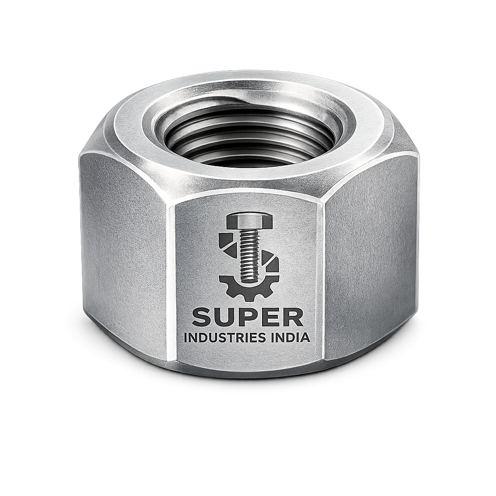
Prevailing Torque Nuts are deployed in fastening systems where joint integrity must be maintained under dynamic service conditions, particularly in assemblies exposed to vibration, cyclic loading, and thermal variation. These nuts are not auxiliary locking devices—they are integrated self-locking components designed to maintain clamp load stability throughout the service life of the joint.
Role in Critical Engineering Assemblies
In engineered systems, the reliability of a bolted joint depends on sustained preload. Any loss of preload results in:
- Joint separation
- Micro-movement between mating surfaces
- Progressive loosening
- Fatigue failure of fasteners
Prevailing Torque Nuts are used to mitigate these risks by introducing controlled frictional resistance within the thread interface, independent of the clamping force.
Application Environments
Prevailing Torque Nuts are commonly specified in the following sectors:
Oil & Gas
- Flanged joints in upstream and downstream pipelines
- Compressor skids and rotating equipment foundations
- Offshore structural connections
Refineries & Petrochemical Plants
- High-temperature process equipment
- Pressure vessel assemblies
- Structural supports subjected to vibration
Power Plants (Thermal, Nuclear, Renewable)
- Turbine casing assemblies
- Boiler structures
- Wind turbine tower and nacelle connections
Heavy Machinery & Mining Equipment
- Dynamic load-bearing joints
- Impact-prone bolted assemblies
- Excavators, crushers, and drilling rigs
Steel Plants
- Rolling mill structures
- Furnace assemblies
- High-temperature structural connections
Railways & Infrastructure
- Track fastening systems
- Bridge structural joints
- Vibration-sensitive mechanical connections
Why Self-Locking Fasteners Are Required
Standard nuts rely solely on friction generated by preload. Under vibration, this friction is gradually overcome due to:
- Transverse movement
- Cyclic stress relaxation
- Embedment losses
- Thermal expansion and contraction
This leads to self-loosening, a well-documented failure mechanism in bolted joints.
Prevailing Torque Nuts address this by:
- Introducing mechanical interference within threads
- Maintaining residual friction even after preload reduction
- Providing secondary resistance to rotation
Failure Risks of Standard Nuts
Without locking mechanisms, standard nuts are susceptible to:
| Failure Mode | Description |
|---|---|
| Self-loosening | Loss of clamp load under vibration |
| Fatigue failure | Crack initiation due to cyclic loading |
| Joint slip | Loss of friction between joint surfaces |
| Bolt shear | Resulting from joint movement |
| Loss of alignment | Critical in rotating equipment |
Comparison with Alternative Locking Methods
Double Nutting
- Relies on jamming action between two nuts
- Requires additional space and assembly time
- Inconsistent preload retention
Lock Washers
- Provide limited resistance under high vibration
- Ineffective in high-load or dynamic applications
- Prone to flattening and loss of function
Adhesive Locking (Threadlockers)
- Dependent on surface condition and curing
- Limited temperature range
- Difficult disassembly
Prevailing Torque Nuts (Engineering Position)
- Integrated locking mechanism
- Predictable torque characteristics
- Suitable for repeated mechanical loading
- No dependency on external components
Super Industries
Global Manufacturer of Heavy & Custom Engineered Fasteners & Flanges
2. Technical Definition
Definition of Prevailing Torque Nuts
A Prevailing Torque Nut is a self-locking threaded fastener designed to:
- Generate resistance to rotation (prevailing torque)
- Maintain this resistance independent of clamp load
- Prevent loosening under vibration and dynamic loading
The defining characteristic is the presence of a locking feature within the nut, which creates interference with the mating bolt thread.
Functional Characteristics
- Resistance exists before full seating of the nut
- Torque required includes:
- Prevailing torque component
- Thread friction torque
- Bearing surface friction
- Locking action remains effective even if preload decreases
Types of Prevailing Torque Nuts
A. All-Metal Prevailing Torque Nuts
- Locking achieved through metal deformation
- Suitable for high-temperature applications
- No polymer components
Sub-types:
- Top lock nuts
- Stover nuts
- Distorted thread nuts
B. Nylon Insert Nuts (Nyloc Type)
- Incorporate a polyamide insert
- Provide elastic deformation against bolt threads
- Limited by temperature range (~120°C typical)
C. Top Lock / Distorted Thread Nuts
- Upper threads are intentionally deformed
- Create elliptical or oval interference zone
- Provide consistent prevailing torque
D. Elliptical Offset Nuts
- Entire thread axis slightly distorted
- Generates uniform interference
- Used in precision assemblies
Prevailing Torque vs Installation Torque
| Parameter | Description |
|---|---|
| Prevailing Torque | Torque required to rotate nut without clamp load |
| Installation Torque | Total torque applied during tightening |
| Relationship | Installation torque = prevailing torque + torque to achieve preload |
Engineering Implication:
Prevailing torque must be accounted for when calculating tightening torque to avoid under-tightening or overloading.
Reusability Considerations
- Prevailing torque reduces with repeated use
- Nylon inserts degrade with thermal exposure
- All-metal nuts show gradual torque decay
Typical reuse limitation:
- Critical applications: Single use recommended
- Non-critical: Limited reuse based on torque verification
Torque Decay Behavior
Over multiple cycles:
- Interference reduces
- Frictional resistance decreases
- Locking effectiveness declines
Therefore, prevailing torque testing is required for reuse validation.
3. Engineering Locking Principle
Thread Interference Mechanism
Prevailing Torque Nuts function by introducing controlled interference between mating threads.
This is achieved through:
- Elastic deformation (nylon insert)
- Plastic deformation (metal distortion)
The result is:
- Increased friction
- Resistance to rotational movement
Elastic vs Plastic Deformation
| Mechanism | Type | Behavior |
|---|---|---|
| Nylon insert | Elastic | Returns to original shape |
| Distorted metal | Plastic | Permanent deformation |
Engineering Impact:
- Elastic systems allow limited reuse
- Plastic systems provide higher temperature stability
Prevailing Torque Generation Zone
The locking zone is typically located:
- At the top section of the nut
- Away from primary load-bearing threads
This ensures:
- Clamp load threads remain functional
- Locking action does not compromise structural strength
Frictional Resistance Development
Resistance to rotation is generated by:
- Increased normal force between threads
- Localized contact pressure
- Surface friction coefficient
This creates a torque threshold that must be overcome for rotation.
Torque–Tension Relationship
In standard fasteners:
- Torque → generates preload
In prevailing torque nuts:
- Torque must first overcome prevailing resistance
- Remaining torque contributes to preload generation
This modifies the torque equation:
- Effective preload torque = Applied torque – Prevailing torque
Clamp Load Retention Under Vibration
Under vibration:
- Standard nuts lose preload due to micro-slip
- Prevailing Torque Nuts maintain resistance due to:
- Continuous thread interference
- Residual frictional force
Junker Vibration Test Concept
The Junker test (transverse vibration test) is used to evaluate self-loosening behavior.
Test Principle:
- Joint subjected to lateral cyclic displacement
- Clamp load measured over time
Observed Results:
- Standard nuts: Rapid preload loss
- Prevailing torque nuts: Controlled preload retention
Self-Loosening Mechanism Prevention
Self-loosening occurs due to:
- Transverse joint movement
- Reduction in friction
- Loss of thread engagement force
Prevailing Torque Nuts prevent this by:
- Maintaining continuous frictional resistance
- Eliminating free rotational movement
- Stabilizing thread engagement
Engineering Summary of Locking Performance
Prevailing Torque Nuts provide:
- Independent resistance to rotation
- Improved preload retention
- Enhanced vibration resistance
- Reduced maintenance requirements
They are therefore specified in:
- Critical joints where failure is not acceptable
- Systems exposed to dynamic and cyclic loading
- Assemblies requiring long-term preload stability
4. Applicable Standards (ASTM / DIN / ISO / ASME)
Prevailing Torque Nuts are governed by a combination of performance standards, dimensional standards, and material specifications. Selection must be aligned with load conditions, temperature exposure, and criticality of application.
ISO Standards
ISO 2320 — Prevailing Torque Performance
This is the primary performance standard for Prevailing Torque Nuts.
Scope:
- Defines minimum and maximum prevailing torque values
- Specifies testing procedures
- Covers torque after multiple tightening cycles
Engineering Relevance:
- Ensures consistent locking performance
- Establishes acceptance criteria for production batches
- Required for EPC and third-party inspection approval
DIN Standards
DIN 980 — All-Metal Prevailing Torque Nuts
- Distorted thread locking mechanism
- Suitable for high-temperature and vibration-prone environments
DIN 982 — Nylon Insert Nuts (High Type)
- Increased height for improved engagement
- Polyamide locking element
DIN 985 — Nylon Insert Nuts (Standard Type)
- General-purpose locking applications
- Limited to moderate temperature environments
ASTM Standards
ASTM A194
- Covers carbon and alloy steel nuts for high-pressure and high-temperature service
- Common grades:
- Grade 2H (alloy steel, high strength)
- Grade 7 / 7M (high-temperature service)
ASTM A563
- Covers carbon steel nuts
- Multiple grades for structural and general engineering use
ASME Standards
ASME B18.16 Series
- Dimensional standards for prevailing torque nuts
- Covers:
- Hex nuts
- Lock nuts
- All-metal prevailing torque configurations
Standards Mapping to Application Conditions
| Standard | Type | Temperature Capability | Typical Application |
|---|---|---|---|
| ISO 2320 | Performance | Depends on material | Qualification & testing |
| DIN 980 | All-metal | High (>300°C) | Turbines, exhaust systems |
| DIN 982 | Nylon insert | ≤120°C | General machinery |
| DIN 985 | Nylon insert | ≤120°C | Light-duty assemblies |
| ASTM A194 | Alloy steel | High | Pressure vessels, flanges |
| ASTM A563 | Carbon steel | Moderate | Structural joints |
| ASME B18.16 | Dimensional | N/A | Standard compliance |
5. Material & Grade Options
Material selection directly governs:
- Mechanical strength
- Temperature resistance
- Corrosion performance
- Long-term locking reliability
Carbon Steel Prevailing Torque Nuts
Applicable Standards:
- ASTM A563
- ISO Property Class 8 / 10
Characteristics:
- Moderate to high strength
- Cost-effective
- Suitable for general industrial applications
Limitations:
- Requires coating for corrosion resistance
- Not suitable for aggressive chemical environments without protection
Stainless Steel Prevailing Torque Nuts
A2-70 (SS304 Equivalent)
- Good corrosion resistance
- Suitable for atmospheric and mild chemical environments
A4-80 (SS316 Equivalent)
- Enhanced resistance to chlorides and marine exposure
- Higher strength than A2-70
Characteristics:
- Non-magnetic (austenitic grades)
- Good temperature resistance (moderate range)
Limitations:
- Lower yield strength compared to alloy steel
- Risk of galling without lubrication
Alloy Steel Prevailing Torque Nuts
Applicable Standard:
- ASTM A194 Grade 2H
Characteristics:
- High tensile and yield strength
- Suitable for high-pressure and high-temperature environments
- Excellent mechanical stability
Applications:
- Pressure vessels
- High-temperature flanges
- Critical bolted joints in EPC projects
High-Temperature Variants
- All-metal prevailing torque nuts preferred
- Nylon insert types not suitable above ~120°C
- Alloy steels with heat treatment used for:
- Boilers
- Turbines
- Exhaust systems
Material Comparison Table
| Grade | Yield Strength (MPa) | Tensile Strength (MPa) | Temperature Range | Corrosion Resistance | Typical Application |
|---|---|---|---|---|---|
| ISO 8 | ~640 | ~800 | -20°C to 300°C | Low (requires coating) | Structural assemblies |
| ISO 10 | ~940 | ~1040 | -20°C to 300°C | Low (requires coating) | High-strength joints |
| ASTM A563 | 400–800 | 600–1000 | Moderate | Low | General engineering |
| ASTM A194 2H | ~850 | ~1000 | Up to 450°C | Moderate (with coating) | Pressure vessels |
| A2-70 (SS304) | ~450 | ~700 | -200°C to 300°C | Good | Chemical & outdoor |
| A4-80 (SS316) | ~600 | ~800 | -200°C to 300°C | Excellent | Marine & offshore |
6. Heat Treatment Information
Heat treatment is critical for achieving:
- Required mechanical properties
- Dimensional stability
- Locking performance consistency
Through Hardening
- Entire nut is hardened uniformly
- Applied to alloy steel grades
Benefits:
- High strength
- Uniform mechanical properties
Case Hardening (Selective Applications)
- Surface hardened, core remains ductile
- Used where wear resistance is required
Tempering
- Performed after hardening
- Reduces brittleness
- Improves toughness
Stress Relieving
- Applied after forming operations
- Reduces residual stresses from deformation
Hardness Ranges
| Grade | Typical Hardness |
|---|---|
| ISO Class 8 | 22–32 HRC |
| ISO Class 10 | 32–39 HRC |
| ASTM A194 2H | 24–35 HRC |
Impact on Locking Performance
- Excessive hardness → risk of cracking in distorted zones
- Insufficient hardness → loss of locking effectiveness
- Controlled hardness ensures:
- Stable deformation
- Consistent prevailing torque
Microstructural Stability
- Tempered martensitic structure for alloy steels
- Austenitic structure for stainless steels
- Stability ensures performance under:
- Cyclic loads
- Thermal exposure
7. Manufacturing Process
Prevailing Torque Nuts require controlled manufacturing to ensure:
- Dimensional accuracy
- Consistent locking torque
- Compliance with standards
Raw Material Inspection
- Chemical composition verification
- Mechanical property validation
- Ultrasonic or visual inspection (if required)
Forging Process
Cold Forging
- Used for small to medium sizes
- High dimensional precision
- Improved grain structure
Hot Forging
- Used for large sizes
- Better material flow
- Suitable for high-strength alloys
Thread Formation
Thread Tapping
- Internal thread cutting
- Controlled pitch and tolerance
Thread Rolling (if applicable)
- Improves surface finish
- Enhances fatigue resistance
Locking Feature Formation
All-Metal Nuts
- Mechanical deformation of top threads
- Ovalization or elliptical distortion
Nylon Insert Nuts
- Machining of insert cavity
- Press-fit insertion of polyamide ring
Heat Treatment
- Carried out as per material grade
- Controlled atmosphere furnaces
- Batch traceability maintained
Surface Finishing
- Zinc plating
- Phosphating
- Hot-dip galvanizing
- Passivation (for stainless steel)
Inspection & Testing
- Dimensional inspection
- Thread gauge verification
- Prevailing torque testing
- Hardness testing
Marking & Traceability
- Grade marking
- Manufacturer identification
- Batch number traceability
Surface Finish Options
Surface finish affects:
- Corrosion resistance
- Friction coefficient
- Torque–tension relationship
Zinc Plating
- Provides basic corrosion protection
- Suitable for indoor and moderate environments
Hot-Dip Galvanizing (HDG)
- Thick zinc coating
- Suitable for outdoor and structural applications
Consideration:
- Requires thread oversizing due to coating thickness
PTFE Coating
- Reduces friction coefficient
- Provides chemical resistance
- Used in offshore and chemical environments
Phosphate Coating
- Provides base for lubrication
- Improves torque consistency
Black Oxide
- Minimal corrosion resistance
- Used for controlled environments
Passivation (Stainless Steel)
- Enhances corrosion resistance
- Removes free iron contamination
Impact of Coating on Torque
| Coating | Friction Coefficient | Torque Impact |
|---|---|---|
| Zinc | Medium | Standard torque values |
| HDG | High variability | Requires correction factor |
| PTFE | Low | Reduced torque required |
| Phosphate | Controlled | Stable torque behavior |
Engineering Note
Surface finish must be considered in torque calculations, as it directly influences:
- Preload achieved
- Risk of over-tightening
- Locking performance consistency
A. Dimensional Table (Representative — Metric Series)
Dimensional conformity is governed by ISO / DIN / ASME standards. The following table provides a reference for standard hex Prevailing Torque Nuts (based on ISO metric threads).
| Thread Size | Pitch (mm) | Nut Height (mm) | Across Flats (mm) | Approx. Weight (kg/1000 pcs) |
|---|---|---|---|---|
| M6 | 1.0 | 5.0 | 10 | 2.5 |
| M8 | 1.25 | 6.5 | 13 | 5.3 |
| M10 | 1.5 | 8.0 | 17 | 10.8 |
| M12 | 1.75 | 10.0 | 19 | 17.5 |
| M16 | 2.0 | 13.0 | 24 | 38.0 |
| M20 | 2.5 | 16.0 | 30 | 75.0 |
| M24 | 3.0 | 19.0 | 36 | 135.0 |
| M30 | 3.5 | 24.0 | 46 | 290.0 |
Engineering Notes:
- Nut height may vary for high-type (DIN 982) vs standard type (DIN 985)
- Locking zone is integrated within upper threads
- For HDG applications, oversize tapping is required
B. Mechanical Property Table
Mechanical properties are derived from material grade and heat treatment condition.
| Property Class / Grade | Yield Strength (MPa) | Tensile Strength (MPa) | Hardness (HRC) | Proof Load (MPa) |
|---|---|---|---|---|
| ISO Class 8 | ≥640 | ≥800 | 22–32 | ~600 |
| ISO Class 10 | ≥940 | ≥1040 | 32–39 | ~830 |
| ASTM A563 (DH) | 655–965 | 830–1210 | 24–34 | ~600–830 |
| ASTM A194 2H | ≥850 | ≥1000 | 24–35 | ~830 |
| A2-70 (SS304) | ≥450 | ≥700 | HRB 85–95 | ~450 |
| A4-80 (SS316) | ≥600 | ≥800 | HRB 95–100 | ~600 |
Engineering Interpretation:
- Proof load defines maximum allowable preload without permanent deformation
- Hardness directly affects locking deformation stability
- Higher grades require controlled torque application
C. Torque Chart
Tightening torque values must account for:
- Thread size
- Material grade
- Surface condition (dry vs lubricated)
- Prevailing torque contribution
Typical Tightening Torque Values (Metric Threads)
| Thread Size | Property Class | Dry Torque (Nm) | Lubricated Torque (Nm) |
|---|---|---|---|
| M6 | 8 | 10 | 7 |
| M8 | 8 | 25 | 18 |
| M10 | 8 | 50 | 35 |
| M12 | 8 | 85 | 60 |
| M16 | 8 | 210 | 150 |
| M20 | 8 | 410 | 290 |
| M24 | 8 | 710 | 500 |
| Thread Size | Property Class | Dry Torque (Nm) | Lubricated Torque (Nm) |
|---|---|---|---|
| M10 | 10 | 70 | 50 |
| M12 | 10 | 120 | 85 |
| M16 | 10 | 300 | 210 |
| M20 | 10 | 580 | 410 |
| M24 | 10 | 1000 | 700 |
Engineering Notes:
- Values are indicative; project specifications override
- Lubrication reduces friction → increases preload at same torque
- Prevailing torque must be added to tightening torque
D. Preload Calculation Guide
Torque–Tension Relationship
![\[T = K \cdot F \cdot d\]](https://superindustriesindia.in/wp-content/ql-cache/quicklatex.com-637ae80de10d14a2f4d17cc6dfd9f1fa_l3.png "Rendered by QuickLaTeX.com")
Where:
- T = Applied torque (Nm)
- K = Torque coefficient (dimensionless, typically 0.10–0.25)
- F = مطلوب clamp force / preload (N)
- d = Nominal bolt diameter (m)
Engineering Interpretation
- Torque is an indirect method of controlling preload
- Friction accounts for ~85–90% of applied torque
- Only ~10–15% contributes to actual bolt tension
Sample Engineering Calculation
Given:
- Bolt size: M16 (d = 0.016 m)
- Required preload: 120 kN
- Torque coefficient (K): 0.20
Calculation:
![\[T = 0.20 \times 120000 \times 0.016\]](https://superindustriesindia.in/wp-content/ql-cache/quicklatex.com-37a5bf2a05a4ffb2e8801533d1979937_l3.png "Rendered by QuickLaTeX.com")
![\[T = 384 \, \text{Nm}\]](https://superindustriesindia.in/wp-content/ql-cache/quicklatex.com-0864fffee1d0265f601877042af02490_l3.png "Rendered by QuickLaTeX.com")
Adjustment for Prevailing Torque
If prevailing torque = 40 Nm:
![\[T_{\text{total}} = 384 + 40 = 424 \, \text{Nm}\]](https://superindustriesindia.in/wp-content/ql-cache/quicklatex.com-a875179ab2d307a73bdeacd52b1b6005_l3.png "Rendered by QuickLaTeX.com")
Safety Factor Consideration
- Typical preload = 70–75% of proof load
- Safety factor ensures:
- No yielding under service
- Resistance to fatigue failure
Engineering Guidance
- Always measure prevailing torque separately
- Apply torque in controlled sequence
- Validate preload using calibrated tools
E. Prevailing Torque Performance Table
Based on ISO 2320 guidelines (indicative values):
| Thread Size | Min Prevailing Torque (Nm) | Max Installation Torque (Nm) | Typical Reuse Cycles |
|---|---|---|---|
| M6 | 0.5 | 10 | 3–5 |
| M8 | 1.0 | 25 | 3–5 |
| M10 | 1.5 | 50 | 3–5 |
| M12 | 2.0 | 85 | 2–4 |
| M16 | 3.0 | 210 | 2–4 |
| M20 | 5.0 | 410 | 1–3 |
Engineering Notes:
- Prevailing torque must remain within specified range after cycles
- Excessive torque → risk of thread damage
- Low torque → ineffective locking
F. Corrosion Resistance Comparison Table
| Material | Marine Environment | Chemical Exposure | High Humidity | Hydrocarbon Service |
|---|---|---|---|---|
| Carbon Steel (Plated) | Low | Low | Moderate | Moderate |
| SS304 (A2-70) | Moderate | Moderate | High | Good |
| SS316 (A4-80) | High | High | Excellent | Excellent |
| Alloy Steel (Coated) | Moderate | Moderate | Moderate | High |
Engineering Interpretation:
- SS316 preferred for offshore and marine
- Alloy steel preferred for high load + high temperature
- Coating selection critical for carbon steel
8. Inspection & Quality Control Methods
Prevailing Torque Nuts used in EPC projects require multi-stage inspection and validation.
PrevailingTorque Testing (ISO 2320)
Procedure:
- Nut rotated on test bolt
- Torque measured:
- First installation
- Subsequent cycles
Acceptance Criteria:
- Torque must fall within specified range
- Consistency across batch required
Proof Load Testing
- Nut subjected to axial load
- Ensures no thread stripping or deformation
- Confirms structural integrity
Hardness Testing
Methods:
- Rockwell (HRC / HRB)
- Vickers (HV)
Purpose:
- Validate heat treatment
- Ensure correct mechanical properties
Thread Gauge Inspection
- GO / NO-GO gauges
- Ensures compliance with:
- ISO 6H
- UNC/UNF 2B
Coating Thickness Testing
- Magnetic thickness gauge
- X-ray fluorescence (XRF)
Ensures:
- Uniform coating
- Corrosion protection compliance
Non-Destructive Testing (NDT)
Magnetic Particle Inspection (MPI)
- Detects surface cracks in ferromagnetic materials
Dye Penetrant Inspection (DPI)
- Detects surface discontinuities
Certification & Documentation
EN 10204 Certification
| Type | Description |
|---|---|
| 3.1 | Manufacturer test certificate |
| 3.2 | Third-party verified certificate |
Third-Party Inspection (TPI)
Conducted by:
- Independent inspection agencies
- Client-appointed inspectors
Scope:
- Dimensional verification
- Mechanical testing
- Documentation audit
- Witness testing
Batch Traceability
Each batch is traceable through:
- Heat number
- Production lot
- Inspection records
Inspection Summary
Prevailing Torque Nuts must comply with:
- Dimensional standards
- Mechanical requirements
- Locking torque performance
- Surface finish specifications
9. Industries Served
Oil & Gas (Upstream, Midstream, Downstream)
Application Areas:
- Pipeline flange assemblies
- Valve mounting systems
- Compressor and pump skids
- Offshore structural joints
Engineering Requirements:
- Resistance to vibration and pressure cycling
- Compatibility with high-strength bolting (ASTM A193 / A194 combinations)
- Corrosion protection in hydrocarbon and saline environments
Preferred Configurations:
- ASTM A194 Grade 2H (all-metal prevailing torque nuts)
- PTFE-coated or phosphate-finished variants
Power Generation (Thermal, Nuclear, Renewable)
Application Areas:
- Turbine casing bolts
- Boiler structural assemblies
- Wind turbine tower connections
- Generator base frames
Engineering Requirements:
- High-temperature resistance
- Fatigue resistance under cyclic loading
- Long-term preload retention
Preferred Configurations:
- Alloy steel prevailing torque nuts
- DIN 980 all-metal lock nuts
Refineries & Petrochemical Plants
Application Areas:
- Pressure vessels
- Heat exchangers
- Structural pipe racks
- Reactor assemblies
Engineering Requirements:
- Chemical resistance
- Stability under thermal expansion
- Prevention of joint loosening in vibrating systems
Railways & Transportation Infrastructure
Application Areas:
- Track fastening systems
- Bogie assemblies
- Bridge structural joints
Engineering Requirements:
- Resistance to continuous vibration
- Shock load absorption
- Minimal maintenance cycles
Heavy Engineering & Mining Equipment
Application Areas:
- Crushers and mills
- Excavators and drilling rigs
- Material handling systems
Engineering Requirements:
- High impact load resistance
- Protection against loosening under dynamic loads
- Robust locking performance
Structural Steel & Infrastructure Projects
Application Areas:
- Steel structures
- Bridges
- Industrial buildings
- Transmission towers
Engineering Requirements:
- Long-term joint stability
- Environmental durability
- Compliance with structural design codes
Wind Energy Sector
Application Areas:
- Tower flange connections
- Nacelle assemblies
- Blade mounting systems
Engineering Requirements:
- Resistance to cyclic wind loading
- Fatigue durability
- Corrosion resistance (offshore installations)
10. Export Capability & Global Supply
Super Industries supplies Prevailing Torque Nuts for international EPC projects with structured export systems aligned to project documentation and compliance requirements.
Export Regions
- United States
- European Union
- Middle East (UAE, Saudi Arabia, Qatar, Oman)
- Southeast Asia
- Africa
Packaging Standards
Packaging is aligned with export logistics and preservation requirements:
- Moisture-resistant packaging
- VCI (Volatile Corrosion Inhibitor) wrapping
- Wooden pallets / fumigated crates (ISPM 15 compliant)
- Segregated batch packaging
Export Documentation
Each shipment is supported with:
- Commercial Invoice
- Packing List
- Mill Test Certificates (EN 10204 3.1 / 3.2)
- Certificate of Origin
- Third-Party Inspection Reports (if applicable)
Batch Traceability & Identification
- Heat number traceability
- Lot-wise production records
- Marking as per ASTM / ISO requirements
- Inspection linkage with documentation
Project Supply Capability
Super Industries supports:
- Bulk EPC project supply
- Multi-size and multi-grade packaging
- Scheduled dispatch aligned with project timelines
- Documentation compliance for global tenders
11. Procurement & Installation View
Installation Torque vs Prevailing Torque
In Prevailing Torque Nuts:
- Total applied torque =
- Prevailing torque
- Thread friction torque
- Bearing friction torque
Engineering Requirement:
- Prevailing torque must be measured and added to calculated tightening torque
Lubrication Considerations
Lubrication directly affects:
- Friction coefficient
- Torque–tension relationship
- Risk of over-tightening
Guidelines:
- Use controlled lubrication (e.g., MoS₂, PTFE)
- Maintain consistency across batch installation
- Adjust torque values accordingly
Reuse Limitations
- Nylon insert nuts: Limited reuse due to insert wear
- All-metal nuts: Gradual reduction in prevailing torque
Engineering Practice:
- Critical applications: Single-use recommended
- Reuse only after verifying prevailing torque values
Assembly Best Practices
Torque Application
- Use calibrated torque wrenches
- Apply torque gradually
- Avoid impact tightening in critical joints
Torque Sequence
For multi-bolt assemblies:
- Cross-pattern tightening
- Multi-stage torque application (30% → 60% → 100%)
Inspection Checkpoints
- Verify thread condition
- Check prevailing torque before installation
- Confirm final torque value
- Record installation data (for EPC documentation)
Storage Conditions
- Store in dry, controlled environment
- Avoid contamination with moisture or chemicals
- Protect nylon insert nuts from UV and heat exposure
- Maintain original packaging until use
12. Custom Engineering Capabilities
Super Industries supports project-specific customization for Prevailing Torque Nuts based on EPC and consultant requirements.
Non-Standard Thread Sizes
- Metric fine threads
- UNC / UNF / UNEF series
- Custom pitch configurations
Controlled Locking Torque Ranges
- Application-specific prevailing torque values
- Adjusted through deformation control or insert design
High-Temperature Variants
- All-metal locking systems
- Alloy steel grades for elevated temperature service
Custom Surface Coatings
- PTFE (low friction, chemical resistance)
- Zinc-nickel plating
- Hot-dip galvanizing with thread compensation
- Phosphate + lubrication systems
Project-Specific Marking
- Client-specific identification codes
- Heat number marking
- Grade and standard marking
- Traceability aligned with EPC documentation
13. Engineering Conclusion
Prevailing Torque Nuts are not general-purpose fasteners. They are engineered locking components used in applications where:
- Joint failure is not acceptable
- Vibration-induced loosening is a known risk
- Preload retention is critical for system integrity
Their performance is governed by:
- Controlled thread interference
- Material and heat treatment selection
- Compliance with ISO 2320 and related standards
- Proper installation and torque management
For EPC and consultant-driven projects, selection of Prevailing Torque Nuts must consider:
- Mechanical strength requirements
- Environmental exposure conditions
- Temperature limits
- Locking performance validation
- Inspection and certification requirements
Final Engineering Position
A correctly specified and properly installed Prevailing Torque Nut:
- Maintains clamp load under vibration
- Reduces risk of self-loosening
- Enhances fatigue life of bolted joints
- Supports long-term operational reliability
This aligns with the requirements of:
- Pressure systems
- Rotating equipment
- Structural assemblies
- High-integrity mechanical systems