
Hydraulic Flanges
1. Industry Context & System Relevance
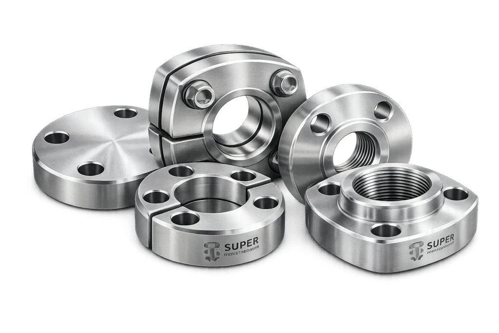
Hydraulic flanges are pressure-retaining mechanical interfaces used in high-pressure fluid power systems where threaded or welded joints are either structurally insufficient or operationally restrictive. In capital-intensive projects—particularly within oil & gas, power generation, offshore systems, and heavy industrial hydraulics—flanged hydraulic connections are selected for their predictable load distribution, repeatable sealing integrity, and maintainable assembly architecture.
In modern hydraulic systems operating between 210 bar and 420 bar (3,000–6,000 PSI) and above, internal pressure generates axial separation forces proportional to system pressure and port area. When this force exceeds the structural or sealing limits of threaded connections, flange systems provide:
- Controlled bolt-preload-based sealing
- Distributed clamping force over a defined sealing face
- Resistance to vibration-induced loosening
- Serviceability without structural rework
- Repeatable torque-to-preload conversion
Hydraulic flanges are commonly deployed in:
- Blowout preventer control systems
- Offshore hydraulic power units (HPUs)
- Subsea hydraulic manifolds
- Turbine lubrication circuits
- Heavy equipment hydraulic circuits
- Steel mill hydraulic cylinders
- Press and forging machine hydraulic assemblies
- LNG terminal loading arms
- Infrastructure lifting and actuation systems
In EPC projects, hydraulic flange selection is rarely aesthetic or cost-driven. It is driven by:
- Pressure class compatibility
- Fatigue life requirements
- Temperature envelope
- Material compatibility
- Third-party inspection compliance
- Documentation traceability
Flange-based hydraulic connections are typically preferred where:
- Repeated maintenance cycles are expected
- System pressures exceed threaded joint safety margins
- Dynamic load and impulse spikes are present
- Installation access is restricted
- Alignment precision is critical
Hydraulic flanges form part of the pressure boundary. Therefore, dimensional precision, bolt selection, surface finish control, and gasket geometry are not optional considerations—they define system reliability.
Super Industries
Global Manufacturer of Heavy & Custom Engineered Fasteners & Flanges
2. Technical Definition of Hydraulic Flanges
Hydraulic flanges are bolted mechanical joint assemblies designed to connect pipes, tubes, valves, pumps, cylinders, and manifolds in high-pressure hydraulic systems. They operate through controlled bolt preload that compresses a sealing element (O-ring or gasket) between two mating faces to prevent leakage under internal pressure.
A standard hydraulic flange assembly consists of:
- Flange head (integral or loose)
- Companion flange or split flange clamp
- O-ring (in groove type systems)
- High-strength bolts
- Port interface surface
Hydraulic flange systems are primarily governed by ISO 6162 (Part 1 & Part 2), which defines two major pressure classes:
- Code 61 – Standard Pressure Series (approx. 3,000 PSI class)
- Code 62 – High Pressure Series (approx. 6,000 PSI class)
Common configurations include:
- 2-bolt flanges
- 4-bolt flanges
- Split flange clamps
- Straight flange heads
- 90° elbow flange heads
- Tee flange bodies
- Bulkhead flange connectors
Unlike threaded joints where sealing occurs at the thread interface or via sealant, hydraulic flanges rely on face compression and controlled bolt tension.
3. Engineering & Sealing Principle
The sealing integrity of hydraulic flanges is governed by bolt preload and compression mechanics.
3.1 Bolt Preload Fundamentals
When a bolt is torqued, it elongates elastically and generates clamping force across the flange faces. This clamping force must exceed:
- Axial separation force generated by internal pressure
- External bending loads
- Vibrational forces
- Thermal expansion differentials
If bolt preload is insufficient, leakage or joint separation may occur.
The basic preload relationship:

Where:
- F = Bolt preload force
- T = Applied torque
- K = Nut factor (friction coefficient)
- d = Nominal bolt diameter
Preload must be engineered within:
- 60–75% of bolt yield strength (typical hydraulic practice)
- Safe elastic range to prevent permanent bolt elongation
3.2 Axial Separation Force Due to Internal Pressure
Internal hydraulic pressure creates a separating force:

Where:
- P = Internal pressure
- A = Effective port area
For example:
At 420 bar (6,000 PSI) and a 38 mm bore, axial separation forces become substantial, requiring precise bolt sizing and torque calibration.
3.3 O-Ring Compression Logic
In ISO 6162 systems, sealing is achieved through:
- Machined O-ring groove in flange face
- Controlled squeeze percentage (typically 15–25%)
- Elastomer compatibility with hydraulic fluid
Critical parameters:
- Groove depth tolerance
- Surface roughness (Ra typically ≤ 3.2 µm)
- Concentricity with bore
- Flatness of mating face
Improper compression results in:
- Extrusion failure
- Cold flow
- Leakage under impulse load
3.4 Surface Finish & Face Geometry
Hydraulic flange faces require:
- Controlled flatness
- Parallelism between mating surfaces
- Specified surface finish (typically Ra 1.6–3.2 µm)
- Burr-free bolt holes
- Chamfer control
Surface irregularities create localized stress concentrations and leakage pathways.
4. Pressure & Load Engineering Relevance
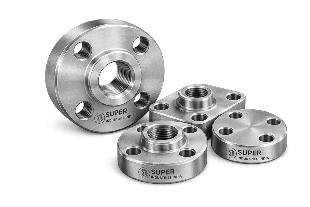
Hydraulic flanges are classified based on pressure capacity and mechanical robustness.
4.1 Pressure Classes
| Series | Typical Rating | Approx. Bar | Application |
|---|---|---|---|
| Code 61 | 3,000 PSI | ~210 bar | Standard hydraulic circuits |
| Code 62 | 6,000 PSI | ~420 bar | High-pressure systems |
| Custom | 10,000+ PSI | 700+ bar | Specialized equipment |
Pressure ratings depend on:
- Material yield strength
- Bolt grade
- Flange thickness
- Port diameter
- Operating temperature
4.2 Static vs Dynamic Loading
Hydraulic systems may experience:
- Steady-state pressure
- Pressure spikes
- Pulsation cycles
- Shock loads
- Vibration-induced micro-movement
Fatigue resistance is critical. Flange systems must withstand:
- Millions of pressure cycles
- Thermal cycling
- Structural bending
Bolt fatigue is influenced by:
- Preload ratio
- Surface finish
- Thread quality
- Corrosion exposure
4.3 Safety Margin Philosophy
Engineering practice typically requires:
- Bolt stress < 75% of yield strength
- Gasket compression within elastic recovery limits
- Pressure rating with defined safety factor (often 4:1 burst ratio)
Hydraulic flanges in EPC projects are evaluated not only for nominal pressure rating, but for:
- Worst-case transient conditions
- Temperature derating
- Material degradation over lifecycle
5. Dimensional & Design Logic
Dimensional control defines interchangeability and sealing performance.
Critical dimensional parameters include:
- Bolt Circle Diameter (BCD)
- Port bore diameter
- Flange thickness
- O-ring groove depth
- Bolt hole diameter tolerance
- Face flatness
- Perpendicularity of bore to face
Deviation in BCD may result in:
- Bolt misalignment
- Uneven preload
- O-ring distortion
Flange thickness must resist:
- Bending under bolt load
- Pressure-induced face rotation
Typical tolerance controls include:
- ±0.05 mm on critical sealing dimensions
- Controlled concentricity between bore and bolt circle
- ISO tolerance classes for machined surfaces
6. Configuration & System Integration
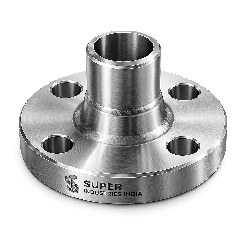
Hydraulic flanges are not standalone components; they integrate with:
- Pumps
- Valves
- Manifolds
- Cylinders
- Steel piping systems
- High-pressure hoses
Common configurations:
- Straight flange head
- 90° elbow flange
- 45° elbow flange
- Tee configuration
- Cross configuration
- Bulkhead flange connector
Each configuration must maintain:
- Uniform wall thickness
- Flow path smoothness
- Structural integrity at directional change
Elbow flanges require additional stress evaluation due to:
- Directional hydraulic force
- Bending stress concentration
7. Why Hydraulic Flanges Over Threaded Systems
In high-pressure systems, threaded joints may introduce:
- Stress concentration at thread root
- Risk of galling
- Sealant degradation
- Alignment challenges
Hydraulic flanges provide:
- Distributed clamping force
- Predictable torque-preload conversion
- Simplified maintenance access
- Reduced risk of thread stripping
- Improved fatigue performance
In offshore and EPC environments, maintainability and inspection visibility are decisive factors.
8. Engineering Evaluation Criteria (EPC Perspective)
During technical evaluation, engineers verify:
- Compliance with ISO 6162
- Material certification traceability
- Heat treatment records
- Bolt grade compatibility
- Dimensional inspection reports
- Surface finish verification
- PMI results
- Pressure rating calculations
- Third-party inspection documentation
Hydraulic flanges must satisfy:
- Design verification
- Manufacturing control
- Inspection traceability
- Installation clarity
Failure in any of these dimensions may disqualify a supplier in project bidding stages.
9. Applicable Standards Framework (ASTM / DIN / ISO / ASME / EN)
Hydraulic flanges used in EPC and capital projects must comply with dimensional, material, and pressure boundary standards. Selection is governed not by availability, but by service condition, regulatory framework, and consultant approval matrix.
9.1 ISO Standards
ISO 6162-1 – Hydraulic fluid power — Four-bolt split-flange connections — Part 1: Code 61 (Standard Pressure Series)
ISO 6162-2 – Hydraulic fluid power — Four-bolt split-flange connections — Part 2: Code 62 (High Pressure Series)
These standards define:
- Bolt circle diameter
- Flange thickness
- O-ring groove geometry
- Bolt size
- Pressure rating envelopes
ISO 6162 ensures global interchangeability between hydraulic components manufactured across different countries.
9.2 ASTM Material Standards
Material compliance is defined through ASTM specifications, commonly including:
| Material Category | ASTM Specification | Typical Use |
|---|---|---|
| Carbon Steel Forgings | ASTM A105 | Standard pressure hydraulic flanges |
| Low Temperature CS | ASTM A350 LF2 | Sub-zero applications |
| Stainless Steel | ASTM A182 F304 / F316 | Corrosive & offshore service |
| Alloy Steel | ASTM A182 F11 / F22 | Elevated temperature hydraulic systems |
| Bolting | ASTM A193 B7 / B16 | High strength bolting |
ASTM standards govern:
- Chemical composition
- Mechanical properties
- Heat treatment requirements
- Testing obligations
9.3 DIN & EN Standards
Where European projects apply:
- DIN EN 10222 – Forged steel components
- DIN EN 10204 – Inspection certificates (3.1 / 3.2)
- EN ISO 898-1 – Mechanical properties of fasteners
DIN compliance is often required for EU project supply.
9.4 ASME Standards (Where Applicable)
Although hydraulic flanges are primarily ISO governed, certain installations interface with ASME piping systems:
- ASME B16.5 (pipe flanges & flanged fittings)
- ASME Section II (material specifications)
- ASME Section VIII (pressure boundary design context)
ASME relevance applies in integrated pressure vessel or piping systems.
10. Material & Grade Options for Hydraulic Flanges
Material selection is governed by:
- Pressure rating
- Operating temperature
- Corrosion environment
- Fatigue cycle requirements
- Project specification
10.1 Carbon Steel Grades
ASTM A105
- Forged carbon steel
- Suitable for ambient temperature hydraulic systems
- High machinability
- Economical for large project volumes
Typical yield strength: ~250 MPa minimum
ASTM A350 LF2
- Low temperature carbon steel
- Suitable down to -46°C
- Impact tested (Charpy V-notch)
- Used in cold climate hydraulic systems
10.2 Stainless Steel Grades
ASTM A182 F304
- Austenitic stainless steel
- Moderate corrosion resistance
- Suitable for general industrial and offshore conditions
ASTM A182 F316
- Molybdenum-enhanced stainless steel
- Improved resistance to chloride pitting
- Common in marine and offshore hydraulic circuits
10.3 Duplex & Super Duplex Stainless Steels
- High yield strength (~450–550 MPa typical)
- Excellent chloride resistance
- Used in offshore and subsea hydraulic assemblies
10.4 Alloy Steel Grades
ASTM A182 F11
- Chromium-molybdenum alloy
- Moderate elevated temperature capability
ASTM A182 F22
- Higher chromium-molybdenum content
- Improved creep resistance
- High temperature hydraulic applications
11. Material Comparison Table (Engineering Reference)
| Grade | Yield Strength (MPa) | Tensile Strength (MPa) | Temp Range (°C) | Corrosion Resistance | Typical Industry Use |
|---|---|---|---|---|---|
| A105 | ≥ 250 | 485–620 | -29 to 425 | Low | General hydraulic systems |
| A350 LF2 | ≥ 250 | 485–620 | -46 to 345 | Low | Cold climate installations |
| A182 F304 | ≥ 205 | 515–720 | -196 to 870 | Moderate | Industrial / mild marine |
| A182 F316 | ≥ 205 | 515–720 | -196 to 870 | High (chloride resistant) | Offshore & marine |
| Duplex 2205 | ≥ 450 | 620–880 | -50 to 300 | Very High | Offshore platforms |
| F22 | ≥ 275 | 485–655 | Up to 600 | Moderate | Elevated temperature |
Material selection must consider:
- Galvanic compatibility
- Fluid composition
- External exposure
- Maintenance interval
12. Heat Treatment Information
Heat treatment influences:
- Yield strength
- Toughness
- Microstructure stability
- Fatigue resistance
Hydraulic flanges intended for EPC projects undergo controlled thermal processing.
12.1 Normalizing
- Refines grain structure
- Improves mechanical uniformity
- Applied to carbon steels
12.2 Quenching & Tempering
- Increases strength
- Enhances fatigue resistance
- Controls hardness
Used in alloy steel hydraulic flanges.
12.3 Solution Annealing (Stainless Steel)
- Dissolves carbides
- Restores corrosion resistance
- Removes cold work stresses
12.4 Stress Relieving
- Reduces residual machining stresses
- Prevents distortion during service
- Improves dimensional stability
12.5 Impact Testing
For low-temperature service:
- Charpy V-notch testing
- Minimum energy absorption per specification
- Ensures brittle fracture resistance
13. Manufacturing Process – Hydraulic Flanges
Manufacturing of hydraulic flanges follows a controlled, documented process sequence.
Step 1 – Raw Material Verification
- Mill Test Certificate review
- Heat number verification
- PMI testing (if required)
- Chemical composition confirmation
Step 2 – Forging
Closed-die forging ensures:
- Grain flow alignment
- Improved mechanical strength
- Reduced porosity
Forging temperature and deformation ratios are controlled.
Step 3 – Rough Machining
- CNC turning
- Bore machining
- Face preparation
Maintains dimensional allowance for finishing.
Step 4 – Heat Treatment (As Required)
Applied per material specification.
Hardness testing performed post heat treatment.
Step 5 – Finish Machining
- Bolt circle drilling
- O-ring groove machining
- Surface finish control
- Concentricity verification
Critical tolerances maintained within engineering specification.
Step 6 – Surface Treatment
Applied based on service environment.
Step 7 – Inspection & Testing
- Dimensional inspection
- NDT (as specified)
- Certification documentation
Step 8 – Marking & Traceability
Hydraulic flanges are marked with:
- Material grade
- Heat number
- Size
- Pressure class
- Manufacturer identification
Ensures full project traceability.
14. Surface Finish Options
Surface treatment depends on environment and project specification.
Carbon Steel Options:
- Black oxide coating
- Zinc electroplating
- Hot-dip galvanizing
- Phosphate coating
- PTFE coating (where specified)
Stainless Steel:
- Pickling & passivation
- Electropolishing (optional)
Surface Roughness Requirements
Typical Ra values:
- Flange face: 1.6–3.2 µm
- O-ring groove: controlled per ISO
Surface finish directly affects sealing performance and fatigue life.
15. Inspection & Quality Control Methods
Hydraulic flanges supplied to EPC projects require documented inspection.
15.1 Dimensional Inspection
- Vernier & micrometer checks
- CMM verification (where required)
- Bolt circle precision measurement
15.2 Mechanical Testing
- Tensile testing
- Hardness testing
- Impact testing
15.3 Non-Destructive Testing (NDT)
- UT (Ultrasonic Testing)
- MPI (Magnetic Particle Inspection)
- DPI (Dye Penetrant Inspection)
Applied as per project ITP.
15.4 PMI (Positive Material Identification)
Used for alloy verification.
15.5 Hydrostatic Testing (If Applicable)
Pressure validation of assembled flange system.
15.6 Documentation
- EN 10204 3.1 certificate
- EN 10204 3.2 (with TPI)
- Heat traceability records
- Inspection reports
Engineering Control Perspective
Hydraulic flanges are evaluated on:
- Dimensional discipline
- Material traceability
- Heat treatment compliance
- Surface finish control
- Bolt compatibility
- Pressure rating verification
In EPC procurement, documentation integrity carries equal weight to mechanical integrity.
16. Dimensional Reference Tables – ISO 6162 Hydraulic Flanges
The following tables summarize typical dimensional relationships for commonly used Code 61 and Code 62 hydraulic flanges. Actual production dimensions must comply with ISO 6162 tolerances and approved manufacturing drawings.
16.1 Code 61 (Standard Pressure Series ~3000 PSI)
| Nominal Size | Port Bore (mm) | Bolt Size | Bolt Circle (mm) | Flange Thickness (mm) | Typical Pressure (bar) |
|---|---|---|---|---|---|
| 1/2″ | 13 | M8 | 34 | 14 | 210 |
| 3/4″ | 19 | M10 | 42 | 16 | 210 |
| 1″ | 25 | M12 | 50 | 18 | 210 |
| 1-1/4″ | 32 | M14 | 62 | 22 | 210 |
| 1-1/2″ | 38 | M16 | 70 | 24 | 210 |
| 2″ | 50 | M20 | 84 | 30 | 210 |
Code 61 flanges are typically used in:
- Standard hydraulic power packs
- Industrial equipment
- Low to moderate pressure circuits
16.2 Code 62 (High Pressure Series ~6000 PSI)
| Nominal Size | Port Bore (mm) | Bolt Size | Bolt Circle (mm) | Flange Thickness (mm) | Typical Pressure (bar) |
|---|---|---|---|---|---|
| 1/2″ | 13 | M10 | 40 | 18 | 420 |
| 3/4″ | 19 | M12 | 48 | 22 | 420 |
| 1″ | 25 | M16 | 60 | 26 | 420 |
| 1-1/4″ | 32 | M18 | 70 | 30 | 420 |
| 1-1/2″ | 38 | M20 | 84 | 34 | 420 |
| 2″ | 50 | M24 | 102 | 40 | 420 |
Code 62 flanges incorporate:
- Increased flange thickness
- Larger bolt diameter
- Higher clamping capacity
- Enhanced impulse resistance
17. Pressure Rating & Safety Margin Table
Hydraulic flange performance depends on bolt strength and material yield limits.
| Series | Nominal Pressure (bar) | Nominal Pressure (PSI) | Typical Safety Factor | Estimated Burst Margin |
|---|---|---|---|---|
| Code 61 | 210 | 3000 | 3.5 – 4 : 1 | ≥ 840 bar |
| Code 62 | 420 | 6000 | 3 – 4 : 1 | ≥ 1500 bar |
| Custom High Pressure | 700 | 10000 | Project specific | Design verified |
Safety factor considers:
- Bolt yield
- Flange bending stress
- Gasket compression limits
- Dynamic loading
18. Bolt Torque Chart for Hydraulic Flanges
Correct torque application ensures sufficient preload without exceeding bolt yield.
Torque values depend on:
- Bolt grade
- Lubrication condition
- Friction coefficient
The following values are general engineering reference for ISO property class 8.8 and 10.9 bolts.
18.1 Torque Values – Dry Condition
| Bolt Size | Grade 8.8 Torque (Nm) | Grade 10.9 Torque (Nm) |
|---|---|---|
| M8 | 25 | 35 |
| M10 | 50 | 70 |
| M12 | 85 | 120 |
| M16 | 210 | 295 |
| M20 | 410 | 580 |
| M24 | 710 | 1000 |
18.2 Torque Values – Lubricated Condition
| Bolt Size | Grade 8.8 Torque (Nm) | Grade 10.9 Torque (Nm) |
|---|---|---|
| M8 | 18 | 26 |
| M10 | 36 | 50 |
| M12 | 65 | 90 |
| M16 | 160 | 225 |
| M20 | 320 | 450 |
| M24 | 560 | 800 |
Lubrication reduces friction factor (nut factor K), resulting in lower torque requirement for equivalent preload.
19. Preload Calculation Guide
Hydraulic flange reliability depends on proper preload engineering.
19.1 Basic Torque–Preload Relationship
Where:
F = Bolt preload force (N)
T = Applied torque (Nm)
K = Nut factor (0.18–0.25 typical)
d = Nominal bolt diameter (m)
19.2 Axial Separation Force
Where:
P = Internal pressure (Pa)
A = Effective port cross-sectional area (m²)
19.3 Sample Engineering Calculation
Example:
- Port diameter = 38 mm
- Pressure = 420 bar (42 MPa)
Area:

Pressure force:


Total bolt preload (combined) must exceed separation force with safety margin.
If 4 bolts are used:
Required preload per bolt: 
Preload typically designed at 2–3 times separation force for safety.
19.4 Bolt Stress Calculation

Where:
σ = Bolt stress
F = Preload force
A_b = Bolt tensile stress area
Bolt stress must remain below 75% of yield strength.
20. Mechanical Property Table
Mechanical properties of commonly used flange materials:
| Material | Yield Strength (MPa) | Tensile Strength (MPa) | Elongation (%) | Hardness (HB) | Impact Resistance |
|---|---|---|---|---|---|
| A105 | ≥ 250 | 485–620 | ≥ 22 | 137–187 | Moderate |
| A350 LF2 | ≥ 250 | 485–620 | ≥ 22 | ≤ 187 | High (low temp tested) |
| A182 F304 | ≥ 205 | 515–720 | ≥ 30 | ≤ 201 | Good |
| A182 F316 | ≥ 205 | 515–720 | ≥ 30 | ≤ 217 | Good |
| Duplex 2205 | ≥ 450 | 620–880 | ≥ 20 | ≤ 293 | High |
21. Yield Strength Comparison (Engineering Interpretation)
Relative yield strength ranking:
Alloy Steel F22
Carbon Steel A105
Stainless Steel 304 / 316
Higher yield strength enables:
- Reduced flange thickness
- Higher pressure rating
- Increased bolt preload tolerance
However, corrosion resistance and temperature limits must also be evaluated.
22. Corrosion Resistance Comparison Table
| Material | Marine Environment | Chloride Exposure | Acidic Conditions | Hydrocarbon Exposure | Typical Use |
|---|---|---|---|---|---|
| Carbon Steel | Low | Poor | Poor | Good | Indoor hydraulic systems |
| A350 LF2 | Low | Poor | Poor | Good | Cold industrial systems |
| SS304 | Moderate | Moderate | Moderate | Good | General industrial |
| SS316 | High | High | Moderate | Excellent | Offshore / marine |
| Duplex 2205 | Very High | Excellent | High | Excellent | Offshore platforms |
Material selection must align with:
- External atmosphere
- Fluid chemistry
- Maintenance interval
- Cathodic protection system
23. Installation Engineering – Torque & Tightening Sequence
Hydraulic flange installation requires controlled tightening.
23.1 Cross Pattern Tightening
Bolts tightened in:
- Initial snug torque
- 50% torque
- 100% final torque
- Verification pass
Ensures:
- Uniform gasket compression
- Prevents flange face distortion
23.2 Re-Torque Practice
For critical systems:
- Re-torque after initial pressure cycle
- Verify preload after thermal stabilization
23.3 O-Ring Handling
- Inspect for cuts or deformation
- Apply compatible lubricant
- Avoid over-compression
24. Dimensional Verification Checklist
During inspection, verify:
- Bolt circle diameter
- O-ring groove depth
- Face flatness
- Surface finish
- Concentricity
CMM measurement recommended for large project volumes.
Engineering Control Perspective
Hydraulic flanges in high-pressure systems are not selected solely by nominal size. Engineers evaluate:
- Bolt preload capacity
- Yield strength margin
- Corrosion resistance
- Fatigue performance
- Surface finish quality
- Documentation traceability
Dimensional accuracy and preload discipline directly influence leak integrity and long-term reliability.
25. Industry Application Mapping
Hydraulic flanges are selected in sectors where pressure integrity, maintainability, fatigue resistance, and dimensional interchangeability are mandatory.
25.1 Upstream Oil & Gas
Hydraulic flanges are deployed in:
- Blowout preventer (BOP) control circuits
- Subsea hydraulic control modules
- Offshore drilling rigs
- Wellhead control systems
- Hydraulic choke and manifold systems
Engineering requirements typically include:
- Code 62 high-pressure series
- ASTM A182 F316 or Duplex materials for marine exposure
- High-strength bolting (ASTM A193 B7 / B16)
- Full traceability documentation
- NDT verification
Offshore environments demand resistance to:
- Salt spray corrosion
- Cyclic pressure fatigue
- Thermal variation
- Vibration from drilling operations
25.2 Refineries & Petrochemical Plants
Hydraulic flanges are used in:
- Actuated valve control systems
- Hydraulic power units
- Emergency shutdown (ESD) systems
- Catalyst handling equipment
- Loading arm actuation
Material selection considerations:
- Hydrocarbon compatibility
- Elevated temperature exposure
- Resistance to chemical washdowns
Carbon steel may be acceptable for indoor service; stainless steel or alloy steel required for aggressive environments.
25.3 Power Generation
Applications include:
- Turbine lubrication systems
- Hydraulic governing systems
- Ash handling hydraulics
- Cooling water hydraulic actuators
In thermal and combined cycle plants, temperature stability and fatigue resistance become critical.
Alloy steel grades such as F11 or F22 may be selected where elevated temperature operation exists.
25.4 LNG & Cryogenic Installations
Hydraulic flanges in LNG systems require:
- Low-temperature toughness
- Charpy impact tested materials
- Austenitic stainless steels or low-temperature carbon steel
Hydraulic actuation in LNG loading arms demands:
- Seal integrity under low ambient temperatures
- Thermal contraction compatibility
- Controlled bolt preload
25.5 Hydrogen Systems
Hydrogen service introduces:
- Risk of hydrogen embrittlement
- Material compatibility concerns
- Surface finish importance
Material and heat treatment processes must mitigate:
- High-strength bolt susceptibility
- Microstructural vulnerability
25.6 Offshore & Marine Infrastructure
Typical installations:
- Floating production storage units (FPSO)
- Offshore platforms
- Marine cranes
- Subsea actuation systems
Duplex and Super Duplex materials are frequently selected due to:
- High chloride resistance
- Elevated yield strength
- Reduced section thickness requirements
25.7 Heavy Equipment & Steel Industry
Hydraulic flanges used in:
- Press machines
- Rolling mills
- Excavators
- Hydraulic forging presses
Operational conditions include:
- Repeated impulse loads
- Shock vibration
- High dynamic pressure variation
Fatigue resistance and bolt preload consistency are critical.
26. Export Capability & Global Supply Discipline
Hydraulic flanges supplied for international EPC projects must comply with both technical and logistical standards.
26.1 Regions Served
Typical export regions include:
- United States
- European Union
- Middle East (UAE, Saudi Arabia, Qatar)
- Southeast Asia
- Africa
Each region may require:
- ASTM or EN compliance
- Third-party inspection certification
- Project-specific stamping and marking
26.2 Packaging Standards
Export packaging includes:
- Rust preventive coating (for carbon steel)
- Individual poly wrapping (for stainless steel)
- Wooden fumigated crates
- Moisture barrier packing
- Desiccant inclusion for sea freight
Surface protection is critical to preserve sealing face finish.
26.3 Documentation Support
Hydraulic flanges supplied for project execution may include:
- EN 10204 3.1 certification
- EN 10204 3.2 (if required by consultant)
- Raw material MTC
- Heat treatment records
- Hardness test reports
- NDT reports
- Dimensional inspection reports
- PMI records
- Packing list & traceability mapping
Documentation integrity is evaluated during technical bid approval.
26.4 Logistics & Project Scheduling
For capital projects, suppliers must support:
- Batch traceability
- Split shipment capability
- Urgent replenishment
- Project-coded packaging
Manufacturing capacity must align with:
- Project schedules
- Shutdown windows
- Maintenance turnaround timelines
27. Procurement & Technical Evaluation Perspective
From an EPC procurement standpoint, hydraulic flange selection involves multi-layer evaluation.
27.1 Technical Bid Review Criteria
Consultants typically verify:
- Compliance with ISO 6162
- Material grade certification
- Heat treatment procedure compliance
- Bolt compatibility
- Pressure rating validation
- Corrosion suitability
- Surface finish conformity
Deviation from specification may require formal technical clarification.
27.2 Installation & Field Verification Checklist
During site installation, inspectors confirm:
- Bolt grade matches approved specification
- Torque values follow approved torque chart
- Cross-pattern tightening applied
- O-ring correctly seated
- Surface free of contamination
- No flange face damage
Incorrect torque application is a primary cause of leakage.
27.3 Storage & Handling Discipline
Hydraulic flanges must be stored:
- In dry conditions
- On protected racks
- With face protectors installed
- Segregated by material grade
Improper storage can lead to:
- Corrosion at sealing face
- Bolt hole damage
- Loss of traceability
28. Custom Engineering Capability
Capital projects often require non-standard hydraulic flanges.
Custom manufacturing may include:
- Increased flange thickness for higher pressure
- Modified bolt hole pattern
- Special port bore dimensions
- Custom O-ring groove geometry
- Special surface coatings
- Project-specific marking
Engineering validation must address:
- Stress distribution
- Bolt load capacity
- Sealing compression limits
- Compatibility with mating component
Finite element analysis (where required) may be performed for custom high-pressure designs.
29. Quality & Traceability Integration
Hydraulic flanges intended for EPC projects must maintain complete traceability chain:
- Heat number to forging
- Forging to machining batch
- Machining to inspection record
- Inspection to packing lot
Traceability supports:
- Audit compliance
- Failure investigation
- Warranty validation
- Long-term asset integrity
30. Engineering Conclusion
Hydraulic flanges are structural pressure boundary components. Their performance depends on:
- Dimensional precision
- Material integrity
- Controlled heat treatment
- Surface finish accuracy
- Correct bolt preload
- Corrosion compatibility
- Verified inspection discipline
In high-pressure hydraulic systems used across oil & gas, power generation, LNG, offshore, and heavy industrial sectors, flange reliability directly influences system uptime and safety.
From an engineering and procurement perspective, hydraulic flange selection is not a catalog decision. It is an evaluation of:
- Mechanical strength
- Sealing performance
- Fatigue resistance
- Corrosion durability
- Documentation integrity
- Manufacturing discipline
Hydraulic flanges manufactured under controlled forging, machining, heat treatment, inspection, and traceability systems provide predictable pressure containment performance when installed in accordance with torque and preload guidelines.
For EPC contractors, consultants, and hydraulic system engineers, evaluation criteria extend beyond nominal size and pressure rating. The decisive factors are compliance, dimensional control, mechanical reliability, and documentation transparency.
Hydraulic flanges remain a preferred solution in high-pressure hydraulic circuits where structural reliability, maintainability, and standardized interchangeability are required across global projects.