
K – LOCK NUTS
1. Industry Context & System Relevance
Super Industries
“Global Manufacturer of Heavy & Custom Engineered Fasteners for Oil & Gas, Power & EPC Contractors.”
Within modern engineered assemblies, fastening systems are not evaluated as isolated components but as load-retention systems under dynamic conditions. In such systems, K Lock Nuts are deployed specifically to address self-loosening risks induced by vibration, cyclic loading, and thermal variation.
Functional Role in Mechanical Systems
In vibration-prone environments, conventional fastening methods exhibit progressive preload loss, primarily due to:
- Micro-slip between mating threads
- Settlement and embedding losses
- Transverse vibration (lateral displacement)
- Thermal expansion and contraction cycles
K Lock Nuts, classified under all-metal prevailing torque lock nuts, are engineered to maintain clamp load integrity under these operating conditions.
Application Environments
Oil & Gas Structures
Used in:
- Offshore platforms
- Subsea modules
- Pipeline supports
- Pressure equipment assemblies
Requirement:
- Resistance to vibration from flow-induced turbulence
- Reliability under thermal cycling
Rotating Equipment
Applied in:
- Pumps
- Compressors
- Turbines
Requirement:
- Resistance to rotational vibration
- Prevention of progressive loosening under cyclic loading
Power Plants
Used across:
- Boiler structures
- Turbine housings
- Structural steel frames
Requirement:
- Stability under thermal expansion
- Long-term preload retention
Heavy Machinery
Applications include:
- Earthmoving equipment
- Construction machinery
- Material handling systems
Requirement:
- Shock load absorption
- Resistance to impact-induced loosening
Structural Steel Connections
- Bridges
- Industrial structures
- Support frames
Requirement:
- Maintenance-free fastening
- Resistance to wind and cyclic structural loading
Automotive & Rail Assemblies
- Bogie assemblies
- Suspension systems
- Chassis connections
Requirement:
- High vibration resistance
- Fatigue durability
Mining & Earthmoving Equipment
- Crushers
- Conveyor systems
- Excavators
Requirement:
- Extreme vibration tolerance
- Dust and contamination resistance
Wind Energy Systems
- Tower connections
- Nacelle assemblies
Requirement:
- Resistance to cyclic wind loading
- Long-term preload stability
Why K Lock Nuts Are Selected
In EPC and high-reliability assemblies, K Lock Nuts are selected over conventional fastening methods due to measurable engineering advantages.
Compared to Standard Hex Nuts
| Parameter | Standard Hex Nut | K Lock Nuts |
|---|---|---|
| Vibration Resistance | Low | High |
| Preload Retention | Poor under dynamic load | Stable |
| Maintenance Frequency | High | Reduced |
Compared to Double Nutting
- Double nutting relies on jam nut friction, which is:
- Installation-sensitive
- Not reliable under severe vibration
- K Lock Nuts provide:
- Built-in locking mechanism
- Reduced installation variability
Compared to Spring Washers
- Spring washers fail under:
- High clamp loads
- Flattening under load
- K Lock Nuts eliminate dependence on:
- Elastic washer behavior
- Secondary components
Engineering Selection Drivers
K Lock Nuts are specified in EPC projects based on:
- Anti-loosening reliability under transverse vibration
- Reduced maintenance and inspection cycles
- Predictable torque-preload behavior
- Compatibility with high-strength bolting systems
Super Industries
Global Manufacturer of Heavy & Custom Engineered Fasteners & Flanges
2. Technical Definition of K Lock Nuts
Core Definition
K Lock Nuts are defined as:
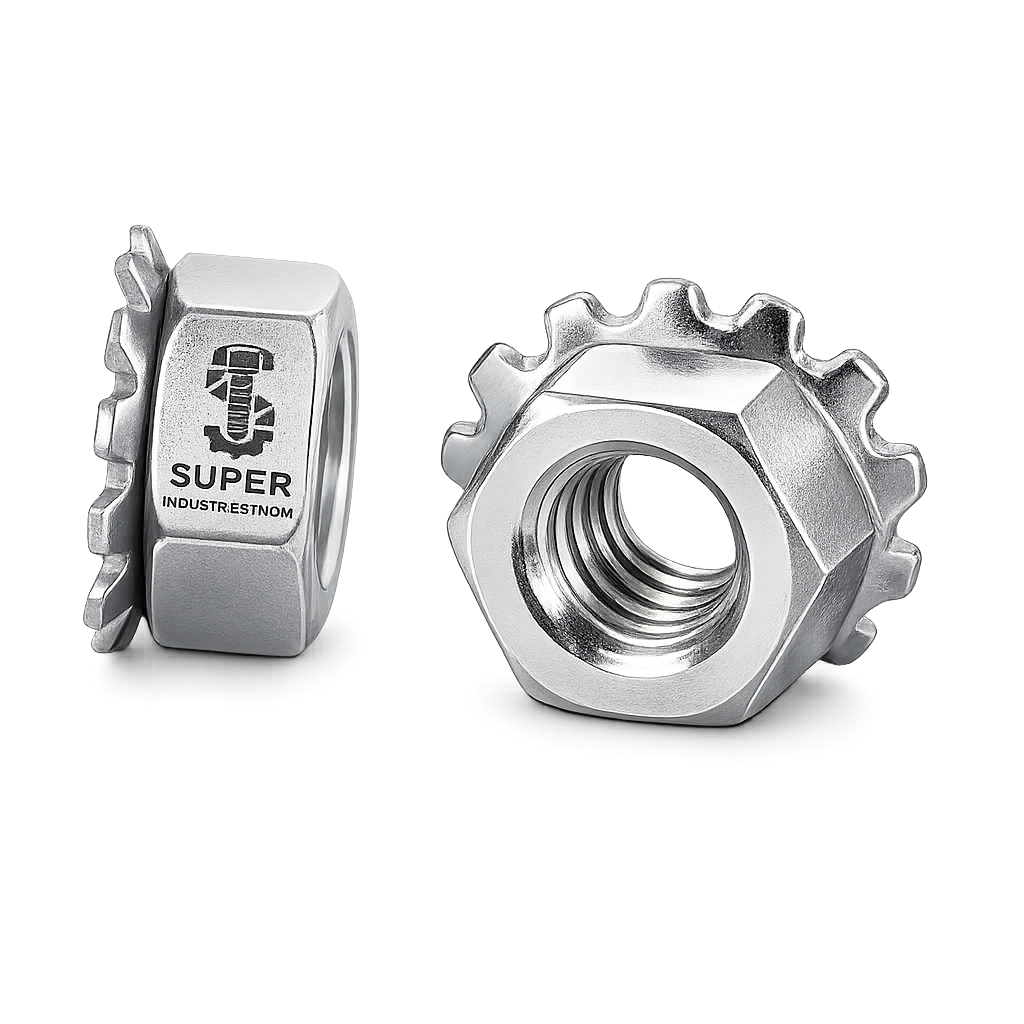
All-metal prevailing torque lock nuts with an integrated free-spinning washer base, serrated bearing surface, and a deformed thread section that generates locking resistance.
Structural Elements
A K Lock Nut consists of:
1. Hexagonal Nut Body
- Standard hex geometry
- Designed for torque application via wrench or socket
2. Integrated Free-Spinning Washer
- Permanently attached but free to rotate
- Functions:
- Reduces surface damage
- Distributes bearing load
- Enhances installation consistency
3. Serrated Bearing Surface
- Located on washer underside
- Provides:
- Anti-rotation resistance
- Increased friction at contact surface
4. Deformed Top Threads (Locking Feature)
- Controlled thread deformation
- Generates prevailing torque
- Creates interference with bolt threads
Locking Mechanism Classification
K Lock Nuts fall under:
- Prevailing Torque Type Lock Nuts
- All-metal self-locking nuts
They comply with standards governing:
- Torque resistance
- Reusability limits
- Thread integrity
Difference from Nylon Insert Lock Nuts
| Parameter | Nylon Insert Nut | K Lock Nuts |
|---|---|---|
| Locking Method | Polymer insert | Metal thread deformation |
| Temperature Resistance | Limited (~120°C) | High temperature capable |
| Chemical Resistance | Limited | Suitable for aggressive environments |
| Reusability | Moderate | Controlled, measurable |
| Fire Safety | Polymer risk | All-metal construction |
Reusability Characteristics
Reusability is governed by:
- Retention of prevailing torque
- Thread wear condition
Typical engineering practice:
- Reuse permitted if:
- Minimum prevailing torque is maintained
- Replacement required if:
- Torque falls below specified limits
Torque Retention Behavior
K Lock Nuts maintain torque through:
- Thread interference
- Frictional resistance
- Serration-induced surface grip
This results in:
- Reduced torque loss under vibration
- Stable clamp load over extended service cycles
3. Engineering Locking Principle
Prevailing Torque Mechanism
The defining feature of K Lock Nuts is the prevailing torque, which is:
The torque required to rotate the nut on the bolt in the absence of axial load.
This is generated through:
- Elastic/plastic deformation of top threads
- Radial pressure against mating bolt threads
Thread Interference Behavior
When engaged:
- Deformed threads create:
- Localized interference zones
- This results in:
- Increased friction
- Resistance to rotation
Frictional Resistance Generation
Friction is generated at two interfaces:
1. Thread Interface
- Between nut and bolt threads
- Primary source of prevailing torque
2. Bearing Surface Interface
- Serrated washer against joint surface
- Prevents rotation under vibration
Clamp Load Retention Under Vibration
In dynamic systems:
- Transverse motion causes:
- Relative displacement
- Loss of preload
K Lock Nuts counteract this via:
- Continuous frictional resistance
- Prevention of rotational back-off
Torque vs Preload Relationship
In fastening systems:
- Applied torque → Generates bolt tension
- Bolt tension → Produces clamp load
However:
- Up to 90% of torque is lost to friction
- Only ~10% contributes to preload
K Lock Nuts improve reliability by:
- Stabilizing friction conditions
- Maintaining consistent preload
Preload Loss in Conventional Nuts
Conventional nuts experience:
- Embedding loss
- Surface flattening
- Thread relaxation
Result:
- Reduction in clamp load
- Increased risk of joint failure
Self-Locking Under Cyclic Loading
Under cyclic loads:
- Standard nuts loosen due to:
- Repeated transverse movement
K Lock Nuts:
- Maintain frictional engagement
- Resist rotation even under repeated cycles
Junker Vibration Test Relevance
The Junker test is the industry benchmark for evaluating:
- Self-loosening behavior under transverse vibration
Observations:
- Standard nuts show rapid preload loss
- K Lock Nuts maintain:
- Higher residual clamp load
- Reduced loosening rate
Slip Resistance vs Rotational Loosening
Two failure modes:
Slip (Joint Movement)
- Controlled by:
- Clamp load
- Surface friction
Rotational Loosening
- Controlled by:
- Thread friction
- Locking mechanism
K Lock Nuts address both through:
- Serrated washer (slip resistance)
- Thread deformation (rotational resistance)
4. Applicable Standards (ISO / DIN / ASTM)
The design, manufacturing, and performance validation of K Lock Nuts are governed by internationally recognized standards that define:
- Mechanical properties
- Thread tolerances
- Prevailing torque requirements
- Inspection and testing procedures
These standards ensure compatibility with high-integrity bolted joints used in EPC projects.
ISO Standards
ISO 7042 – Prevailing Torque Type All-Metal Nuts
Defines:
- All-metal prevailing torque nuts with deformed threads
- Performance criteria for:
- Minimum prevailing torque
- Reusability characteristics
- Torque decay limits
Relevance to K Lock Nuts:
- Governs locking performance
- Ensures repeatable torque resistance
ISO 898-2 – Mechanical Properties of Nuts
Specifies:
- Property classes (e.g., 8, 10, 12)
- Proof load values
- Hardness limits
Engineering relevance:
- Determines compatibility with:
- Bolt grades (8.8, 10.9, 12.9)
- Ensures joint integrity under load
DIN Standards
DIN 980 – All-Metal Self-Locking Nuts
Defines:
- Prevailing torque nuts with:
- Deformed thread locking
- Dimensional and functional characteristics
DIN 6923 – Flange Nuts with Serrations
Defines:
- Nuts with:
- Integrated flange (washer face)
- Serrated bearing surface
Relevance to K Lock Nuts:
- Serrated washer geometry
- Bearing surface interaction
ASTM Standards
ASTM A563 – Carbon Steel Nuts
Covers:
- Carbon steel nuts for:
- Structural and general engineering applications
Defines:
- Strength grades
- Heat treatment conditions
ASTM A194 – Alloy Steel Nuts for High-Pressure Applications
Used in:
- Pressure vessels
- High-temperature piping systems
Grades:
- 2H (quenched and tempered)
Relevance:
- Suitable for:
- High load
- Elevated temperature environments
Standards Mapping to Engineering Use
| Standard | Scope | Load Class | Temperature Suitability | Typical Use |
|---|---|---|---|---|
| ISO 7042 | Prevailing torque nuts | Medium to high | Moderate to high | General mechanical & structural |
| ISO 898-2 | Mechanical properties | Class 8–12 | Depends on material | Bolt-nut compatibility |
| DIN 980 | Lock nut design | Medium to high | Moderate | Industrial fastening |
| DIN 6923 | Serrated flange nuts | Medium | Moderate | Automotive, structural |
| ASTM A563 | Carbon steel nuts | Medium | Low to moderate | Structural steel |
| ASTM A194 | Alloy steel nuts | High | High temperature | Oil & Gas, pressure systems |
5. Material & Grade Options
Material selection for K Lock Nuts is driven by:
- Required mechanical strength
- Corrosion environment
- Operating temperature
- Load conditions
Carbon Steel
Grades
- ISO Property Class 8 / 10
- ASTM A563 Grades
Characteristics
- Moderate strength
- Cost-efficient for structural use
- Suitable for non-corrosive environments
Applications
- Structural steel connections
- General engineering assemblies
Alloy Steel
Grades
- ASTM A194 Grade 2H
- High-strength quenched and tempered grades
Characteristics
- High tensile and yield strength
- Enhanced fatigue resistance
- Suitable for high preload applications
Applications
- Pressure vessels
- High-temperature bolting
- Oil & gas equipment
Stainless Steel
Grades
- A2 (Equivalent to 304)
- A4 (Equivalent to 316)
Characteristics
- Corrosion resistance
- Lower strength compared to alloy steel
- Suitable for chemically aggressive environments
Applications
- Marine structures
- Chemical processing plants
- Offshore systems
Material Comparison Table
| Material Grade | Yield Strength (MPa) | Tensile Strength (MPa) | Temperature Range | Corrosion Resistance | Typical Industry Use |
|---|---|---|---|---|---|
| Class 8 (Carbon Steel) | ~640 | ~800 | -20°C to 300°C | Low | Structural, general engineering |
| Class 10 (Carbon Steel) | ~940 | ~1040 | -20°C to 300°C | Low | High-load structural |
| ASTM A194 2H | ~860 | ~1040 | Up to 450°C | Moderate (coated) | Oil & Gas, pressure systems |
| A2-70 (SS 304) | ~450 | ~700 | -200°C to 300°C | High | General corrosion environments |
| A4-80 (SS 316) | ~600 | ~800 | -200°C to 400°C | Very High | Marine, offshore, chemical |
6. Heat Treatment Information
Heat treatment is critical in ensuring:
- Required mechanical strength
- Thread integrity
- Locking performance
Quenching & Tempering
Applied to:
- Alloy steel nuts
- High-strength carbon steel
Process:
- Heating to austenitizing temperature
- Rapid cooling (quenching)
- Controlled reheating (tempering)
Results:
- Improved strength
- Controlled hardness
- Reduced brittleness
Case Hardening (Selective Use)
In certain designs:
- Surface hardness is increased
- Core remains ductile
Purpose:
- Improve wear resistance of threads
- Maintain locking effectiveness
Stress Relieving
Performed after:
- Thread forming
- Machining
Purpose:
- Reduce residual stresses
- Prevent distortion
- Maintain dimensional stability
Hardness Control
Typical ranges:
- Carbon steel: 20–30 HRC
- Alloy steel (2H): 24–35 HRC
- Stainless steel: Lower hardness, higher ductility
Engineering importance:
- Excess hardness → risk of thread cracking
- Low hardness → loss of locking capability
Impact on Locking Performance
Heat treatment directly affects:
- Thread deformation stability
- Resistance to wear during reuse
- Consistency of prevailing torque
7. Manufacturing Process
The manufacturing of K Lock Nuts follows a controlled, traceable sequence aligned with EPC inspection requirements.
Raw Material Inspection
- Chemical composition verification
- Mill test certificates review
- Visual and dimensional checks
Forging Process
Cold Forging (Preferred for Precision)
- High dimensional accuracy
- Improved grain flow
Hot Forging (For Larger Sizes)
- Used for heavy-duty nuts
- Suitable for large diameters
Thread Tapping / Forming
- Internal threads produced to:
- ISO metric (6H)
- UNC / UNF (2B)
Controls:
- Pitch accuracy
- Thread angle
- Surface finish
Thread Deformation (Locking Feature Creation)
Critical step:
- Top threads are:
- Mechanically deformed
- Precisely controlled
Objective:
- Achieve required prevailing torque
- Maintain repeatability
Washer Integration
- Washer is:
- Permanently attached
- Free to rotate
Ensures:
- Uniform load distribution
- Reduced friction variability
Serration Formation
- Machined or stamped on washer surface
Function:
- Increase friction at contact surface
- Prevent rotational slip
Heat Treatment
- As per material grade
- Controlled atmosphere furnaces
Surface Coating
Applied as per:
- Corrosion requirements
- Project specifications
Final Inspection
Includes:
- Dimensional verification
- Thread gauge testing
- Prevailing torque measurement
Marking & Traceability
Markings include:
- Manufacturer identification
- Grade marking
- Heat number / batch traceability
Traceability ensures:
- Compliance with EPC documentation
- Inspection audit readiness
Dimensional Control Discipline
Critical parameters:
- Across flats (AF)
- Nut height
- Washer diameter
- Thread concentricity
Controlled through:
- Statistical process control (SPC)
- Gauge calibration
Surface Finish Options
Surface treatment impacts:
- Corrosion resistance
- Torque-tension relationship
- Service life
Zinc Plating
- Thickness: 5–25 microns
- Provides:
- Basic corrosion protection
Impact:
- Reduces friction → affects torque values
Hot-Dip Galvanizing (HDG)
- Thickness: 40–80 microns
Advantages:
- High corrosion resistance
- Suitable for outdoor structures
Consideration:
- Thread oversizing required
PTFE Coating
- Low friction coefficient
Benefits:
- Improved torque consistency
- Chemical resistance
Black Oxide
- Minimal corrosion protection
Used for:
- Indoor applications
- Controlled environments
Mechanical Galvanizing
- Uniform coating without hydrogen embrittlement
Used for:
- High-strength fasteners
Coating Impact on Torque
Coatings affect:
- Friction coefficient (K factor)
- Torque-preload relationship
Engineering requirement:
- Torque values must be adjusted based on:
- Coating type
- Lubrication condition
A. Dimensional Table (Representative Engineering Reference)
The following table provides typical dimensions for K Lock Nuts based on metric series. Final dimensions are governed by ISO / DIN standards and project specifications.
| Thread Size | Pitch (mm) | Nut Height (mm) | Across Flats (mm) | Washer Diameter (mm) | Load Class |
|---|---|---|---|---|---|
| M6 | 1.0 | 6.0 | 10 | 14 | Class 8 |
| M8 | 1.25 | 8.0 | 13 | 18 | Class 8 / 10 |
| M10 | 1.5 | 10.0 | 17 | 22 | Class 8 / 10 |
| M12 | 1.75 | 12.0 | 19 | 26 | Class 8 / 10 |
| M16 | 2.0 | 16.0 | 24 | 34 | Class 10 |
| M20 | 2.5 | 20.0 | 30 | 42 | Class 10 |
| M24 | 3.0 | 24.0 | 36 | 50 | Class 10 |
| M30 | 3.5 | 30.0 | 46 | 60 | Class 10 / High Strength |
Dimensional Engineering Notes
- Washer diameter is designed to:
- Increase bearing surface
- Reduce localized stress
- Nut height is selected to:
- Ensure sufficient thread engagement
- Maintain proof load capacity
- Concentricity between:
- Nut thread axis
- Washer face
is critical for uniform load transfer
B. Torque Chart
Torque values for K Lock Nuts depend on:
- Thread size
- Bolt grade
- Surface condition (dry / lubricated)
- Coating type
Torque Values (Metric Threads)
| Thread Size | Bolt Grade | Dry Torque (Nm) | Lubricated Torque (Nm) |
|---|---|---|---|
| M6 | 8.8 | 10 | 7 |
| M8 | 8.8 | 25 | 18 |
| M10 | 8.8 | 50 | 35 |
| M12 | 8.8 | 85 | 60 |
| M16 | 8.8 | 210 | 150 |
| M20 | 8.8 | 410 | 290 |
| M24 | 8.8 | 710 | 500 |
| M30 | 8.8 | 1400 | 1000 |
For Higher Grades
| Thread Size | Bolt Grade | Dry Torque (Nm) | Lubricated Torque (Nm) |
|---|---|---|---|
| M12 | 10.9 | 120 | 85 |
| M16 | 10.9 | 300 | 210 |
| M20 | 10.9 | 600 | 420 |
| M24 | 10.9 | 1000 | 700 |
| M30 | 10.9 | 2000 | 1400 |
Engineering Notes on Torque
- Lubrication reduces:
- Friction coefficient
- Required tightening torque
- Over-torque risks:
- Bolt yielding
- Thread damage
- Under-torque risks:
- Insufficient preload
- Joint separation
C. Preload Calculation Guide
1. Torque–Tension Relationship
\[
F = \frac{T}{K \cdot d}
\]
Where:
- F = Bolt preload (N)
- T = Applied torque (Nm)
- K = Torque coefficient (friction factor)
- d = Nominal diameter (m)
2. Engineering Interpretation
- The torque coefficient (K) varies:
- Dry condition: ~0.18 – 0.25
- Lubricated: ~0.10 – 0.18
- Small variation in K leads to:
- Significant variation in preload
3. Sample Calculation
Given:
- Torque (T) = 300 Nm
- Nominal diameter (d) = 16 mm = 0.016 m
- K = 0.20
Result:
- F = 300 / (0.20 × 0.016)
- F = 93,750 N
4. Safety Factor Consideration
In EPC design:
- Target preload = 70–80% of bolt yield strength
Purpose:
- Prevent yielding
- Maintain clamp load under dynamic conditions
5. Preload Engineering Logic
- Higher preload:
- Improves joint stiffness
- Reduces micro-slip
- Excess preload:
- Leads to bolt failure
D. Mechanical Property Table
| Grade | Yield Strength (MPa) | Tensile Strength (MPa) | Hardness (HRC) | Proof Load (MPa) |
|---|---|---|---|---|
| Class 8 | 640 | 800 | 20–25 | ~600 |
| Class 10 | 940 | 1040 | 25–34 | ~830 |
| ASTM A194 2H | 860 | 1040 | 24–35 | ~830 |
| A2-70 | 450 | 700 | ~20 | ~450 |
| A4-80 | 600 | 800 | ~25 | ~600 |
Engineering Notes
- Proof load defines:
- Maximum load without permanent deformation
- Hardness must be controlled to:
- Avoid brittleness
- Maintain thread integrity
E. Corrosion Resistance Table
| Material | Marine Environment | Industrial Atmosphere | Chemical Exposure | Typical Coating Requirement |
|---|---|---|---|---|
| Carbon Steel | Poor | Moderate | Poor | Zinc / HDG |
| Alloy Steel | Poor | Moderate | Moderate | PTFE / HDG |
| SS 304 (A2) | Good | Good | Moderate | Not required |
| SS 316 (A4) | Excellent | Excellent | High | Not required |
Engineering Interpretation
- Marine environments require:
- Stainless steel (A4) or heavy coatings
- Chemical exposure:
- Requires corrosion-resistant alloys
- Carbon steel must always be:
- Coated for durability
8. Inspection & Quality Control Methods
Inspection of K Lock Nuts is conducted at multiple stages to ensure compliance with EPC specifications and international standards.
Thread Gauge Inspection
Tools:
- Go / No-Go gauges
- Thread pitch accuracy
- Thread fit class (6H / 2B)
Checks:
Prevailing Torque Testing
Critical for lock nuts.
Measured:
- Torque required to rotate nut without axial load
Ensures:
- Locking feature effectiveness
- Compliance with ISO 7042
Proof Load Testing
Purpose:
- Verify load-bearing capacity
Procedure:
- Apply axial load
- Ensure no thread stripping or deformation
Hardness Testing
Methods:
- Rockwell hardness test
Ensures:
- Compliance with material grade
- Proper heat treatment
Coating Thickness Testing
Methods:
- Magnetic thickness gauge
- Micrometer measurement
Ensures:
- Uniform coating
- Corrosion protection compliance
Dimensional Inspection
Checks:
- Across flats
- Nut height
- Washer diameter
- Concentricity
Third-Party Inspection (TPI)
Conducted by:
- Independent inspection agencies
Scope:
- Witness testing
- Document verification
- Batch traceability
Certification
Provided documentation:
- EN 10204 3.1 – Manufacturer test certificate
- EN 10204 3.2 – Third-party verified certificate
Includes:
- Chemical composition
- Mechanical properties
- Test results
Traceability System
Each batch is traceable via:
- Heat number
- Lot number
- Manufacturing records
Ensures:
- Audit compliance
- Project documentation integrity
9. Industries Served
The application of K Lock Nuts is aligned with high-reliability fastening requirements across sectors where vibration resistance, preload retention, and operational safety are critical.
Oil & Gas Industry
Applications:
- Offshore platforms
- Subsea structures
- Pipeline supports
- Pressure-containing equipment
Engineering requirements:
- Resistance to cyclic loading from flow and pressure variations
- Stability under thermal expansion
- Compatibility with high-strength bolting (ASTM A193 / A194 systems)
Power Generation
Applications:
- Thermal power plants
- Gas turbine assemblies
- Nuclear auxiliary systems
Engineering requirements:
- High-temperature stability
- Long-duration preload retention
- Resistance to vibration in rotating equipment
Heavy Engineering & Process Industry
Applications:
- Industrial machinery
- Process equipment
- Structural frames
Engineering requirements:
- Load-bearing reliability
- Resistance to shock and impact loads
- Consistent torque-preload performance
Mining & Earthmoving Equipment
Applications:
- Crushers
- Excavators
- Conveyor systems
Engineering requirements:
- High vibration tolerance
- Resistance to dust contamination
- Minimal maintenance intervention
Railways & Transportation
Applications:
- Bogie assemblies
- Track components
- Structural fastening
Engineering requirements:
- Fatigue resistance under cyclic loading
- Resistance to loosening due to dynamic motion
Infrastructure & Structural Steel
Applications:
- Bridges
- Industrial buildings
- Steel frameworks
Engineering requirements:
- Long-term structural integrity
- Resistance to environmental exposure
- Reduced inspection frequency
Wind & Renewable Energy
Applications:
- Tower connections
- Nacelle assemblies
- Structural joints
Engineering requirements:
- Resistance to fluctuating wind loads
- Long-term preload retention
- Corrosion resistance in outdoor environments
10. Export Capability & Global Supply
Super Industries operates as a manufacturer and exporter of K Lock Nuts with supply capability aligned to EPC project requirements and international compliance frameworks.
Export Regions
Supply coverage includes:
- United States
- European Union
- Middle East (GCC countries)
- Southeast Asia
- Africa (project-based supply)
Packaging Standards
Packaging is designed to ensure:
- Mechanical protection during transit
- Corrosion prevention
- Batch traceability
Typical methods:
- Wooden crates (ISPM-15 compliant)
- Palletized packaging
- Moisture barrier wrapping
- Segregated batch labeling
Export Documentation
Supplied documentation includes:
- Commercial invoice
- Packing list
- Certificate of origin
- Mill test certificates (EN 10204 3.1 / 3.2)
- Inspection release notes
Project Logistics Capability
Support for:
- Bulk project shipments
- Containerized cargo (FCL / LCL)
- Breakbulk (for oversized fasteners)
Coordination includes:
- Dispatch scheduling
- Port documentation
- Freight coordination
Compliance Documentation
Documentation aligned with:
- EPC project specifications
- Client-approved vendor documentation requirements
- Third-party inspection approvals
11. Procurement & Installation View
This section provides a practical engineering and procurement perspective for the use of K Lock Nuts in field applications.
Installation Procedure
- Ensure:
- Clean bolt threads
- No contamination or damage
- Align components:
- Ensure proper seating of joint surfaces
- Hand-tighten nut:
- Until washer contacts surface
- Apply torque:
- Using calibrated torque wrench
- Achieve specified torque:
- As per project torque chart
Torque Application Sequence
For multi-bolt assemblies:
- Use cross-pattern tightening sequence
- Apply torque in stages:
- 30% → 60% → 100% of final torque
Purpose:
- Uniform load distribution
- Prevention of joint distortion
Reusability Guidelines
Reuse permitted only if:
- Prevailing torque remains within specified limits
- Threads show no visible damage
Replacement required if:
- Torque falls below minimum threshold
- Thread deformation is excessive
Inspection Checkpoints (Field)
During installation:
- Verify torque values
- Check washer seating
- Confirm no thread damage
Post-installation:
- Periodic torque verification (if specified)
- Visual inspection for loosening
Storage Conditions
Store under:
- Dry indoor conditions
- Controlled humidity
Avoid:
- Exposure to moisture
- Mixing of batches
Maintain:
- Original packaging for traceability
12. Custom Engineering Capabilities
K Lock Nuts can be engineered for project-specific requirements, particularly in EPC and high-load applications.
Non-Standard Thread Sizes
Capability includes:
- Metric fine threads
- UNC / UNF threads
- Large diameter fasteners
Custom Washer Geometry
Options:
- Increased washer diameter
- Modified thickness
- Application-specific serration patterns
High-Strength Variants
Manufactured using:
- Alloy steel grades
- Heat-treated configurations
Suitable for:
- High preload applications
- Pressure systems
Special Surface Coatings
Available coatings:
- PTFE (low friction)
- Hot-dip galvanizing (HDG)
- Zinc flake coatings
Project-Specific Marking
Marking options:
- Client identification
- Heat number
- Grade marking
Supports:
- Traceability
- Inspection compliance
13. Engineering Conclusion
K Lock Nuts are designed as mechanical locking fasteners that provide:
- Controlled prevailing torque
- Resistance to vibration-induced loosening
- Stable clamp load retention
From an engineering standpoint, their performance is defined by:
- Thread deformation geometry
- Frictional behavior under load
- Compatibility with high-strength bolting systems
When evaluated for EPC applications, selection must consider:
- Load conditions
- Environmental exposure
- Required torque-preload accuracy
- Applicable international standards
Final Engineering Assessment
For applications involving:
- Dynamic loading
- Structural vibration
- Critical joint integrity
K Lock Nuts provide a mechanically reliable and standards-compliant fastening solution when:
- Properly specified
- Correctly installed
- Verified through inspection and testing